NR SA CORESET0
The purpose of this tutorial is Not about creating any specific test cases. This is more about information sharing on how CORESET0 in NR SA is configured automatically by gNB software and how you can configure it manually when you want. SSB positioning and selecting an appropriate CORESET0 resource is one of the most complicated and confusing process in NR protocol, but Amari gNB specifies SSB and corresponding CORESET0 automatically. Of course, you can specify it manually as you like if you want any specific configuration. This tutorial will show you how you can figure out the automatically set configuration and how you can manually change the configuration if you need.
It is assumed that you already have basic understandings on what is the CORESET (If you are not familiar with the concept of the coreset itself, I would suggest to check out this note). CORESET0 is a specially designed coreset only SIB1 scheduling. The details of this CORESET (i.e, SIB1 scheduling information) cannot be broadcasted to UE). Why not ? Except MIB(PBCH), SIB1 is the first broadcast message, so there should be some other mechanism to provide the details of SIB1 sheduling to UE. The technique that 3GPP adopted for this is as follows.
- i) define various predefined set of configuration in 3GPP specification (both gNB and UE should have these predefined table in it)
- ii) Inform the UE on which table and which index of the table to use via MIB (PBCH)
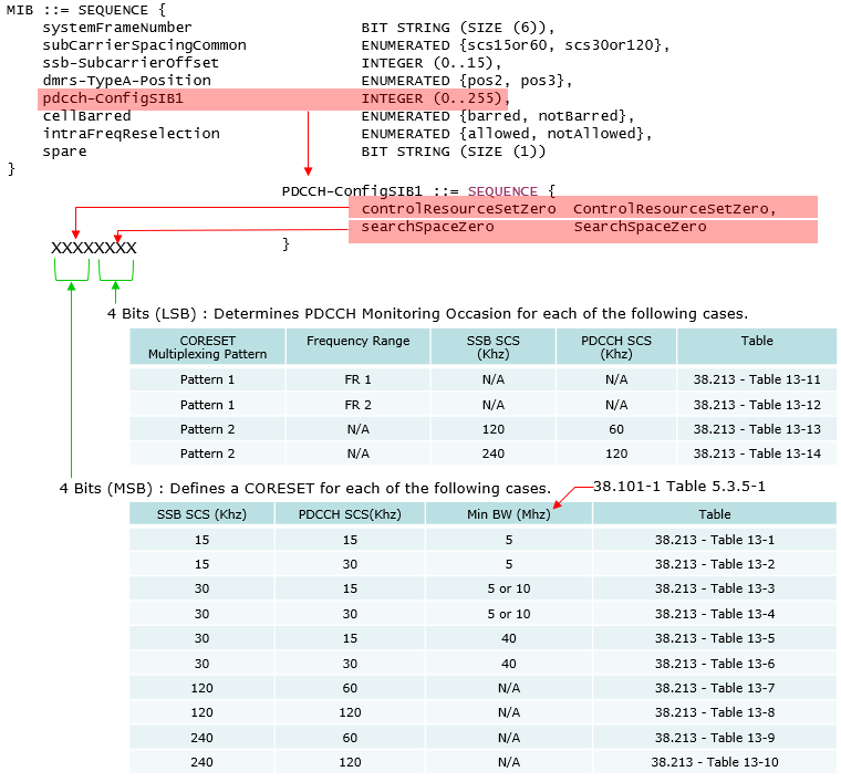
The summary of this mechanism would be illustrated as below (as per my understanding).
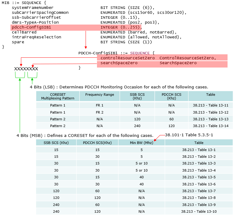
Image Source : SIB1 decoding Procedure in Sharetechnote
In 3GPP, SSB SCS,PDCCH SCS, Min BW determines which table to apply and the MIB parameter determines the index of the selected table. In Amarisoft gNB, SSB SCS,PDCCH SCS, Min BW determines which table to apply and the index of the table is specified in enb.cfg. (The index specified in the configuration file is populated in MIB).
Table of Contents
Introduction
In the landscape of 5G New Radio (NR) Standalone (SA) deployments, the configuration of Control Resource Set 0 (CORESET0) is a critical aspect of initial cell access and broadcast operations. CORESET0 is a specially designated time-frequency resource used for scheduling the first System Information Block (SIB1) after the Master Information Block (MIB) is delivered to User Equipment (UE). This tutorial provides an in-depth look at how CORESET0 is automatically configured by gNB (next-generation NodeB) software, particularly in solutions such as Amarisoft gNB, and how operators or engineers can manually override these settings when specific configurations are desired. The selection and positioning of Synchronization Signal Blocks (SSBs) and their association with CORESET0 is governed by complex rules and standardized tables defined by 3GPP, which both the gNB and UE must interpret consistently. Since details regarding SIB1 scheduling cannot be dynamically broadcast to UEs before SIB1 itself is delivered, the 3GPP specification provides a mechanism where predefined configuration tables are referenced using parameters transmitted via the MIB on the Physical Broadcast Channel (PBCH). This mechanism ensures interoperability and efficient initial access across devices from different vendors. Understanding how these configurations are selected—either automatically by the gNB or manually by the operator—is essential for optimizing network deployment, troubleshooting access issues, and ensuring compliance with 3GPP standards. This tutorial aims to equip you with the knowledge to interpret the gNB's default behavior, recognize the mapping between SSBs and CORESET0, and perform manual configuration as needed to meet specific requirements or deployment scenarios.
-
Context of CORESET0 Configuration in NR SA
- 5G NR introduces a flexible and dynamic resource allocation framework, where the initial system information delivery is tightly coupled with CORESET0 configuration.
- CORESET0 is crucial for SIB1 scheduling, which follows the initial synchronization established by the MIB and SSBs.
- Automatic configuration by gNB software (e.g., Amarisoft) simplifies deployment, but manual configuration enables fine-tuning for specialized scenarios.
-
Relevance and Importance of the Tutorial Topic
- Correct CORESET0 configuration is essential for reliable UE access, proper system information acquisition, and overall network performance.
- Misconfiguration or misunderstanding of CORESET0 and SSB mapping can lead to access failures or interoperability issues between UEs and the gNB.
- This tutorial demystifies the automatic and manual configuration processes, helping network engineers ensure robust and standards-compliant deployments.
-
What You Will Learn
- How CORESET0 is automatically determined by gNB software based on predefined 3GPP tables and broadcast parameters.
- How to interpret which CORESET0 configuration is active using both MIB parameters and gNB configuration files.
- Practical steps to override the automatic configuration and manually specify CORESET0 parameters for custom deployment needs.
- Understanding the linkage between SSB positioning, subcarrier spacing, bandwidth, and corresponding CORESET0 selection.
- Best practices for ensuring compatibility and compliance with the 3GPP specification.
-
Prerequisite Knowledge and Skills
- Familiarity with the fundamentals of 5G NR, including SSB, CORESET, and system information broadcasting.
- Basic understanding of how gNBs are configured, particularly with Amarisoft or similar platforms.
- General knowledge of 3GPP specifications and the role of MIB and SIB1 in NR cell access procedures.
- Optional: Experience with reading and interpreting configuration files (such as enb.cfg) and understanding broadcast channel parameters.
Summary of the Tutorial
This tutorial provides a detailed overview of the procedures for verifying and troubleshooting the automatic configuration of SSB and CORESET0 resources using the Amari gNB software, as well as identifying common misconfigurations related to CORESET0 resource allocation.
-
Automatic Configuration Test Procedures
- The Amari gNB software automatically assigns SSB (Synchronization Signal Block) and CORESET0 configurations if these are not explicitly defined in the configuration file. This includes parameters such as ssb_arfcn, k_ssb, ssb_prb, coreset0_prb (position of coreset0), and coreset0_idx.
- The assigned values are printed as metadata in the gNB logfile. Users are advised to check the beginning of the logfile for these automatically configured values to ensure that the software is running correctly.
-
Example 1: 20 MHz Channel Bandwidth
- Set channel bandwidth to 20 MHz and subcarrier spacing to 30 kHz.
- The software automatically determines and logs SSB and CORESET0 parameters.
-
Example 2: 40 MHz Channel Bandwidth
- Set channel bandwidth to 40 MHz and subcarrier spacing to 30 kHz.
- The software automatically determines and logs SSB and CORESET0 parameters.
-
Example 3: 10 MHz Channel Bandwidth
- Set channel bandwidth to 10 MHz and subcarrier spacing to 30 kHz.
- The software automatically determines and logs SSB and CORESET0 parameters.
- Manual configuration is not recommended for narrow bandwidth scenarios due to increased complexity.
- Users may override the automatic configuration by manually specifying SSB and CORESET0 positions in the configuration file, but this is generally not recommended unless necessary.
-
Common Error Identification Procedures for CORESET0 Resource Allocation
- The section outlines typical misconfigurations that may cause CORESET0 allocation errors and provides test cases to help users identify and rectify them.
-
Example 1: Offset Too Big
- Occurs when the CORESET0 boundary exceeds the channel bandwidth due to an excessively large offset value, even though the CORESET0 bandwidth is narrower than the CBW.
-
Example 2: Frequency Span Too Wide
- Happens when the configured CORESET0 bandwidth is wider than the channel bandwidth.
- Specifically, the number of resource blocks (n_rb_coreset0) assigned to CORESET0 exceeds the maximum supported for the given channel bandwidth and subcarrier spacing.
- For instance, assigning 48 resource blocks for CORESET0 is invalid if the channel bandwidth supports fewer than 48 resource blocks.
- These examples are intended to help users recognize and correct misconfiguration issues by adjusting relevant parameters.
-
Additional Notes
- The tutorial briefly mentions that the Amarisoft Callbox does not print full MIB (PBCH) contents in the trace log, but metadata related to CORESET0 is included in the log for verification.
- For further details on parameter definitions or in-depth technical references, users are directed to external resources.
Automatic Configuration
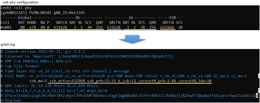
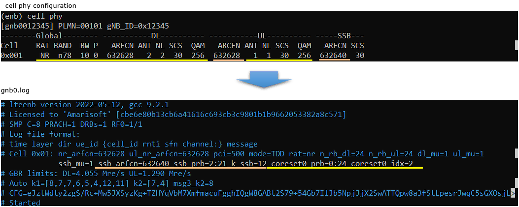
If you don't specify SSB and CORESET0 configuration manually, those are set automatically by Amari gNB. Most of the sample configurations that are installed by the installation package uses the automatic configuration (meaning that those configurations are not set explicitely in the configuration file). Followings are some of the examples showing the result of automatic configuration. You can check the specified SSB and coreset0 resource allocation from the gnb log file as shown below. (
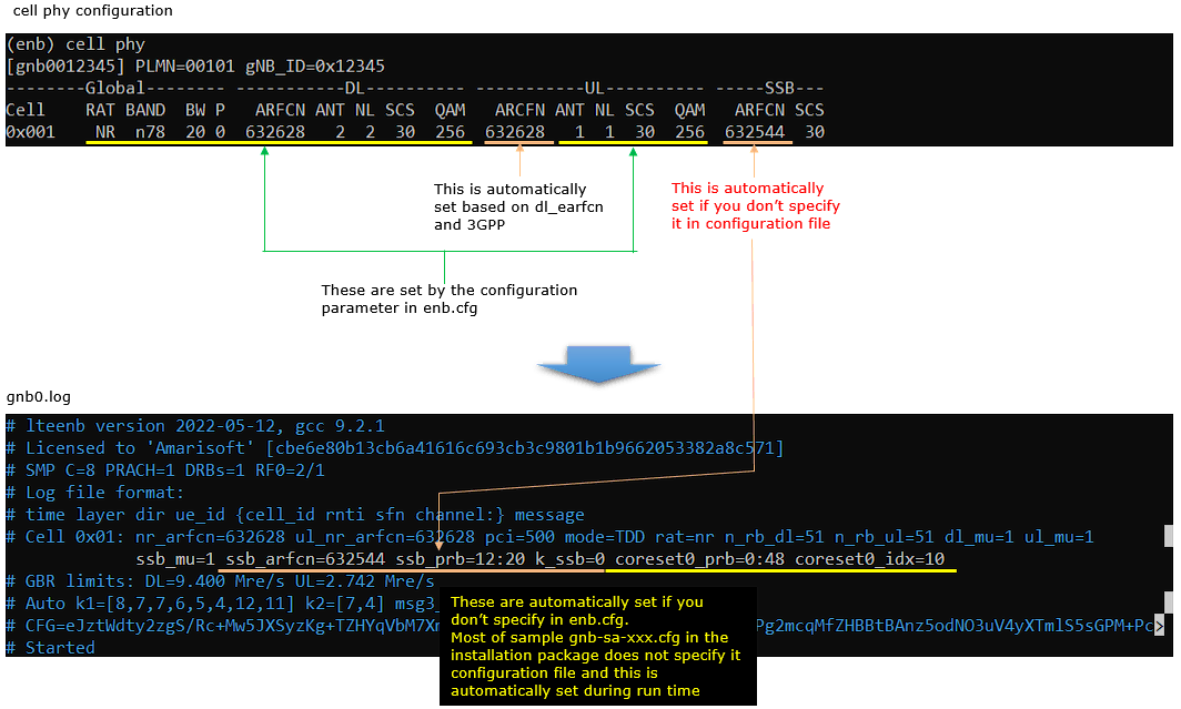
Example 1 > CBW 20 Mhz
In this example, bandwith is configured to be 20Mhz and subcarrier spacing is configured to be 30Khz. Based on this, ssb_arfcn, k_ssb, ssb_prb, coreset0_prb (position of coreset0) and coreset0_idx are all automatically set by LTE software and printed in the logfile as metat data. (
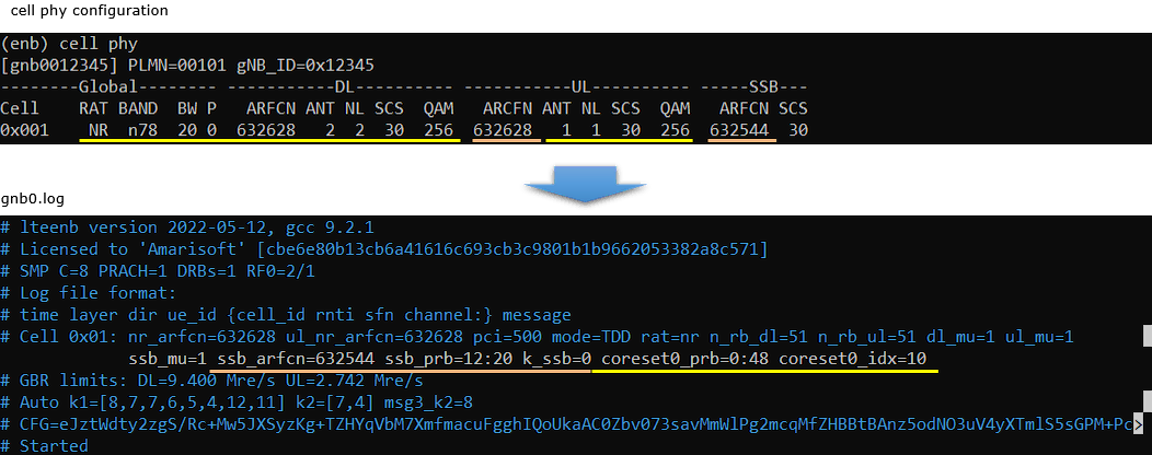
Example 2 > CBW 40 Mhz
In this example, bandwith is configured to be 40Mhz and subcarrier spacing is configured to be 30Khz. Based on this, ssb_arfcn, k_ssb, ssb_prb, coreset0_prb (position of coreset0) and coreset0_idx are all automatically set by LTE software and printed in the logfile as metat data. (
Example 3 > CBW 10 Mhz
In this example, bandwith is configured to be 10Mhz and subcarrier spacing is configured to be 30Khz. Based on this, ssb_arfcn, k_ssb, ssb_prb, coreset0_prb (position of coreset0) and coreset0_idx are all automatically set by LTE software and printed in the logfile as metat data. (
Common Errors for CORESET Resource Allocation
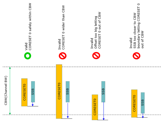
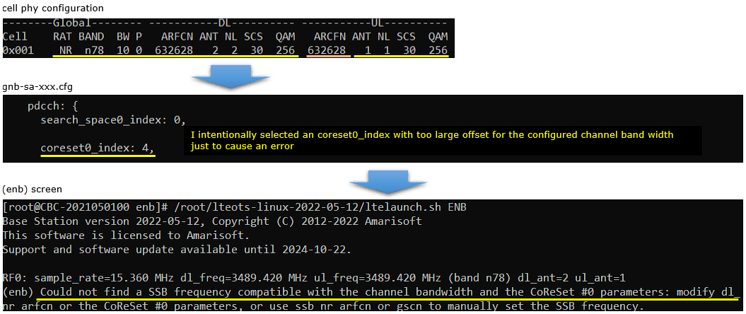
Followings are some of the common misconfigurations causing CORESET0 related errors. (NOTE : This is not the exhaustive list of misconfigurations. These are only examples of common misconfiguration and you may come across various other cases as well). In the examples shown below, I intentionally set the configuration to cause errors, but you can use the same parameter to fix the coreset related errors.
Example 1 > Offset too big
This is the case where coreset 0 bandwidth is narrower than the CBW (channel bandwidth), but the coreset 0 boundary gets out of CBW due to too large offset value
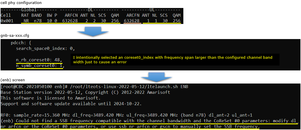
Example 2 > Frequency Span too wide
This is the case where the coreset 0 bandwidthis wider than the configured channel bandwidth. This case can be interpreted as follows :
- The number of RB of the configured coreset 0(n_rb_coreset0) is larger than the max number of RB for the configured channel bandwidth (You can check out the max number of RB for each channel bandwidth and subcarrier spacing in this note)
- For example, you cannot allocate coreset 0 with the NRB(number of RB) of 48 for the channel bandwidth with the max NRB of smaller than 48 (e.g, CBW 5Mhz with SCS 15Khz or CBW 10Mhz with SCS 30Khz).
RRC / NAS Signaling
MIB (SA)
: Amarisoft Callbox does not print out the full contents of MIB (PBCH) in the trace log (The MIB contents related to CORESET 0 is printed in the log at meta data section as shown above). The ASN.1 structure of NR SA MIB is as shown below.
