NR SA CHO(Conditional Handover)
This tutorial shows how to test NR SA to NR SA Conditional Handover. This tutorial also shows how to configure Measurement and Conditional Handover Report and how to trigger measurement report and Handover. Conditional Handover is a procedure of cell change during the connected mode and usually occurs as described below.
Step 1 : Network (gNB) configures measurement request based on the configured measurement trigger to direct UE to perform the measurement
Step 2 : UE perform the measurement and send the report to the network if the measurement result matches the condition set by the measurement request configuration specified at step 1
Step 3 : Network sends RRC message to notify the handover condition (activation condition) to UE
Step 4 : UE continuosly perform the measurement to check if the measurement result meets the handover condition
Step 5 : If the measurement result meets the handover condition (activation condition), the UE executes the handover.
In terms of frequencies of current cell and target/destination cell, the handover can be categorized into two types as below
- Intra Frequency Handover : Current Cell and Target Cell frequency is same
- Inter Frequency Handover : Current Cell and Target Cell frequency is different
Table of Contents
- NR SA CHO(Conditional Handover)
- Introduction
- Summary of the Tutorial
- Test Setup
- Key Configuration Parameters
- Test 1 : TN SA Inter Frequency Conditional Handover - with Cell Power Change
- Test 2 : NTN SA Inter Frequency Conditional Handover - with Event D1
- Test 3 : NTN SA Inter Frequency Conditional Handover - with Event T1
- RRC / NAS Signaling
Introduction
Conditional Handover (CHO) in 5G New Radio (NR) Standalone (SA) networks represents an advanced mobility management mechanism designed to enhance the reliability and efficiency of cell transitions during connected mode. Unlike traditional handover techniques, CHO enables the network to pre-configure multiple potential target cells and associated handover conditions directly on the User Equipment (UE), allowing the UE to autonomously execute a handover when specific radio conditions are met. This architecture reduces handover latency and signaling load, providing significant benefits in highly dynamic radio environments and for mission-critical applications requiring low latency and high reliability. The CHO process leverages the flexible architecture of the NR Radio Resource Control (RRC) layer, where the gNB (Next Generation NodeB) orchestrates measurement configurations and defines activation criteria for handover, while the UE continuously evaluates radio measurements and triggers handover actions as soon as the relevant conditions are satisfied. This tutorial provides a detailed walkthrough of testing NR SA to NR SA Conditional Handover, including the configuration of measurement and CHO reports, the triggering mechanisms for measurement reporting and handover execution, and the categorization of handover scenarios based on frequency relationships between serving and target cells. By understanding the technical architecture and operational workflow of CHO, practitioners can appreciate its role in ensuring seamless connectivity and optimizing mobility in the 5G ecosystem.
-
Context and Background
- 5G NR Standalone (SA) networks introduce advanced mobility solutions, with Conditional Handover being a key mechanism for robust and low-latency cell transitions.
- CHO leverages the RRC layer to coordinate measurement configurations and handover conditions between the gNB and UE.
- Designed to address challenges in dynamic environments, CHO reduces handover failure rates and enhances user experience.
-
Relevance and Importance of the Tutorial
- Understanding and testing Conditional Handover is critical for network engineers, test engineers, and researchers focusing on 5G mobility management.
- Mastery of CHO configuration and testing enables more reliable mobility, critical for applications such as autonomous vehicles, industrial automation, and ultra-reliable low-latency communications (URLLC).
- The tutorial addresses both the theoretical and practical aspects of CHO, bridging the gap between 3GPP standards and real-world implementation.
-
Learning Outcomes
- Gain a comprehensive understanding of the Conditional Handover process in NR SA networks.
- Learn how to configure measurement and CHO reports, and how to trigger measurement reports and handover events.
- Distinguish between intra-frequency and inter-frequency handover scenarios and recognize their implications in network planning and optimization.
- Acquire practical skills for setting up, testing, and validating CHO procedures using standard-compliant tools and methodologies.
-
Prerequisite Knowledge and Skills
- Familiarity with 5G NR architecture, especially the RAN (Radio Access Network) and RRC protocol stack.
- Basic understanding of mobility management concepts, including measurements, handover triggers, and cell reselection.
- Experience with network testing, protocol analysis, or radio network planning will be beneficial.
- Exposure to 3GPP specifications (especially TS 38.331) is advantageous for deeper technical comprehension.
Summary of the Tutorial
This tutorial provides detailed procedures for testing Conditional Handover (CHO) in both Terrestrial NR SA and Non-Terrestrial Network (NTN) NR SA scenarios, focusing on inter-frequency handover using different events and triggers. The tests are structured around specific configurations and stepwise execution, with emphasis on test methodologies, key configuration parameters, and log analysis.
-
Test 1: TN SA Inter-Frequency Conditional Handover - with Cell Power Change
-
Test Procedure:
- Configure two NR SA cells on different frequencies, each with 2x2 MIMO and TDD operation. Use gnb-sa-cho.cfg for gNB and ue-nr-sa-cho.cfg for UEsim or commercial UE. Ensure each cell lists the other as a neighbor and sets conditional_handover_target: true.
- Set up measurement configurations (meas_config_desc) to enable event-based reporting:
- Event A2: Triggered when serving cell RSRP falls below a threshold. Configured with specific RSRP, reporting interval, and time-to-trigger.
- Event A3: Triggered when a neighbor cell becomes better than the serving cell by a defined offset (e.g., 6 dB).
- Enable measurement gaps as needed to support inter-frequency measurements.
- Start LTE/NR service and verify the correct configuration and activation of both cells.
- Adjust cell power dynamically (using cell_gain command) to trigger measurement events and initiate handover.
- Monitor the test terminal output for cell change indication, confirming successful handover execution.
-
Methodology Highlights:
- Conditional Handover is prepared in advance based on measurement events, with the RRC Reconfiguration sent to the UE specifying the conditions and target cell configuration.
- Handover execution occurs only when the configured event (e.g., A3) is satisfied, verified by measurement reports from the UE.
- Log analysis confirms the exchange of capability messages, RRC Reconfiguration with CHO parameters, measurement reporting, and eventual RACH/initiation on the target cell.
-
Test Procedure:
-
Test 2: NTN SA Inter-Frequency Conditional Handover - with Event D1
-
Test Procedure:
- Configure two NR NTN cells in LEO mode with SISO setup and 5 MHz bandwidth, using gnb-sa-ntn-multi-cell_d1.cfg and ue-nr-ntn-multi-cell_d1.cfg.
- Enable satellite channel emulation and set AWGN-only channels for both cells to focus on handover logic.
- Configure NTN-specific measurement and handover triggers:
- Use Event D1 for location-based handover, setting distance_threshold_from_ref1 and from_ref2, with hysteresis and time_to_trigger tailored to LEO NTN geometry.
- Each cell lists the other as a neighbor and as a CHO target.
- Include SIB19 transmission to provide NTN geometry and timing information to the UE.
- For UEsim, set matching ground_position and ensure apply_ta_commands is enabled for correct uplink timing.
- Start services and confirm both NTN cells are active with correct parameters via status and runtime traces.
- Use cell_gain adjustments if required to facilitate event triggers.
- Monitor 't' output and log traces for PRACH on the target cell and cell change confirmation.
-
Methodology Highlights:
- Event D1 enables predictive, geometry-driven CHO, particularly suited for NTN where handover timing can be calculated from satellite or beam movement.
- Important to match configuration of UE and callbox, especially with respect to NTN geometry and ephemeris parameters.
- Log analysis confirms correct establishment of NTN context, SIB19 delivery, event-based reporting, and successful CHO execution upon location-based trigger.
-
Test Procedure:
-
Test 3: NTN SA Inter-Frequency Conditional Handover - with Event T1
-
Test Procedure:
- Similar base setup to Test 2, but uses gnb-sa-ntn-multi-cell_t1.cfg and ue-nr-ntn-multi-cell_t1.cfg with Event T1 as the CHO trigger.
- Event T1 configures a time-based trigger for handover, specifying timeThreshold and duration parameters that allow handover to be executed at a scheduled time, useful for deterministic LEO satellite operations.
- Configure NTN mobility, channel settings, and conditional handover target as described in previous tests.
- Ensure UE and gNB are synchronized in terms of ground position, orbit, and timing parameters.
- Start services, confirm correct setup and operation of both NTN cells, and monitor for successful CHO execution as the T1 time condition is met.
-
Methodology Highlights:
- Event T1 allows for purely time-based CHO trigger, aligning handover with predicted satellite movement rather than signal-level or location-based events.
- Suitable for highly predictable NTN scenarios, such as LEO handover scheduling.
- Log analysis verifies event-based reporting, CHO configuration delivery, and successful transition to the target cell at the preconfigured time trigger.
-
Test Procedure:
General Methodology Across All Tests:
- Careful configuration of both gNB and UE/UEsim is essential, including frequency, antenna setup, NTN-specific parameters, and CHO-specific properties.
- Measurement reporting is enabled and tailored via meas_config_desc to ensure UEs send appropriate triggers to the gNB for CHO initiation.
- Conditional Handover is always prepared in advance, with the UE storing the configuration and executing the handover only when the event condition is satisfied.
- Test execution involves observing terminal traces and logs to confirm correct sequence: capability exchange, measurement configuration, event triggers, CHO command storage, trigger satisfaction, RACH on target cell, and completion of handover.
- Use of cell_gain for power adjustments is preferred over tx_gain to avoid SIB changes that may confuse UEs.
- For commercial UE testing, considerations such as extending inactivity timers or generating continuous traffic are recommended to avoid premature RRC release before CHO execution.
These procedures enable robust and repeatable testing of NR Conditional Handover—both in terrestrial and non-terrestrial environments—using Amarisoft-based setups, flexible configuration, and log-driven verification of test outcomes.
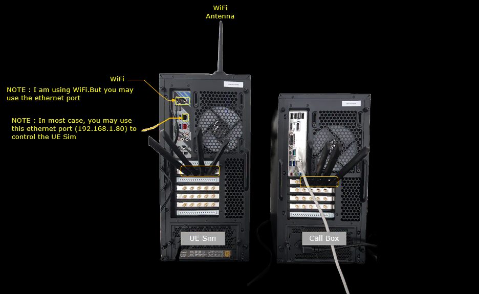
Test Setup
Test setup for this tutorial is as shown below.
- SIM Card used in this tutorial is the one delivered with the system as it is.
- If you want to change the configuration, The tutorial Configuration Guide would help
< Setup A >

< Setup B >
Key Configuration Parameters
Followings are important configuration parameters for this tutorial. You may click on the items for the descriptions from Amarisoft documents.
- ncell_list : In this link, you would get the descriptions for all the items listed below
- meas_config_desc : In this link, you would get the descriptions for all the items listed below
- a1_report_type
- a1_rsrp
- a1_hysteresis
- a1_time_to_trigger
- a2_report_type
- a2_hysteresis
- a2_time_to_trigger
- nr_handover
- nr_conditional_handover
- meas_gap_config
- ho_from_meas
Test 1 : TN SA Inter Frequency Conditional Handover - with Cell Power Change
In this test, I will show on a very simple scenario to trigger an handover between two NR SA cells which is triggered by the direct power change of the cell and the corresponding measurement report from UE.
Configuration
I used the gnb-sa-cho.cfg which is copied and modified from gnb-sa.cfg

I also used mme-ims.cfg as it is.

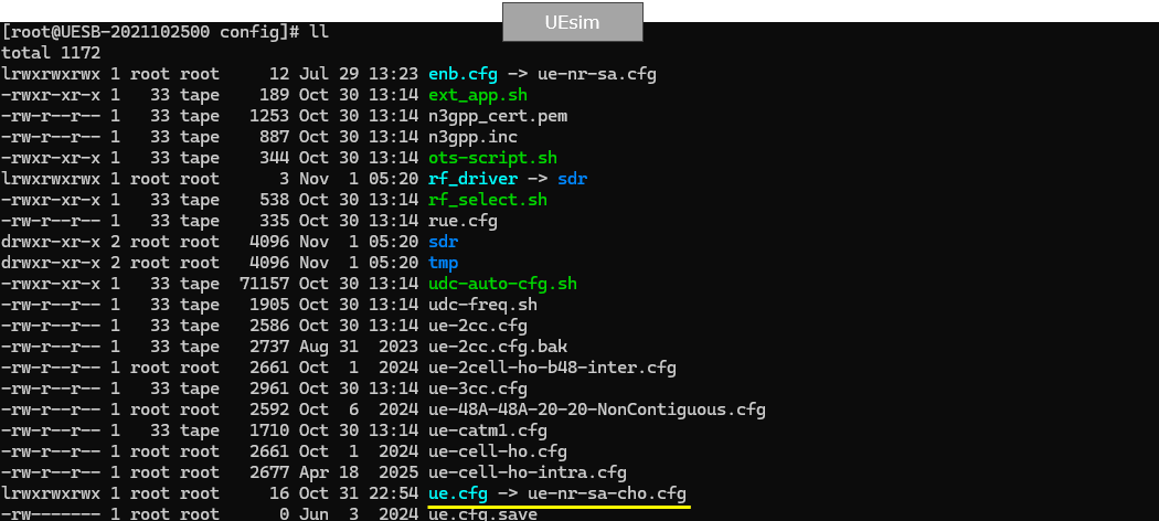
I used the ue-nr-sa-cho.cfg which is copied and modified from ue-nr-sa.cfg
Configure gnb-sa-cho.cfg as below.
You can configure this part in any way you like. In this test, I used TDD (NR_TDD 1), 2x2 MIMO(N_ANTENNA_DL 2) and bandwidth 40 Mhz (NR_BANDWIDTH 20).

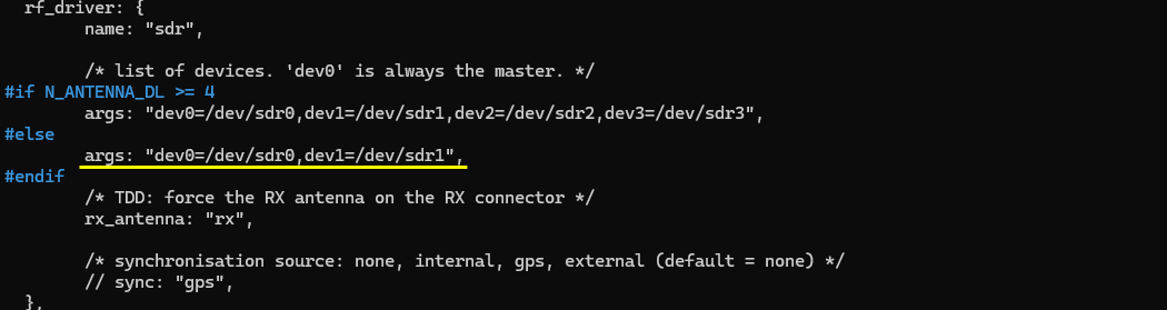
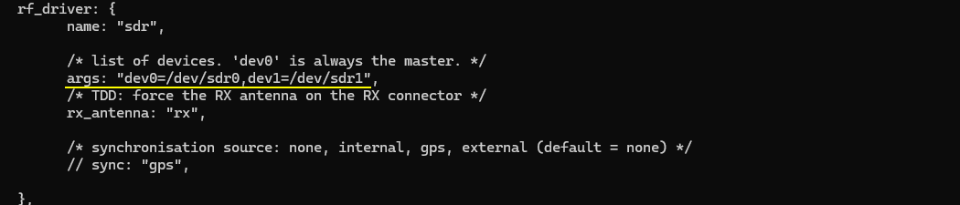
Make it sure that you have enough number of sdr cards for this test in rf_driver. In this test, I am using only 2 cell with 2x2 MIMO, so dev0, dev1 would be good enough.
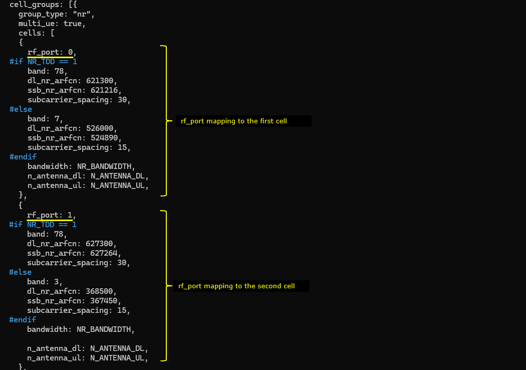
I added neighbour cell list(ncell_list) to the configuration of the first cell and add the second cell(n_id_cell:2) as the neighbour cell and set conditional_handover_target : true to enable conditional handover for the target cell.
As you see, the camping cell (the first cell in this case) and the target cell(the second cell in this case) has different frequency(different dl_earfcn) because this test is for Inter cell Handover.

I added neighbour cell list(ncell_list) to the configuration of the second cell and add the first cell(n_id_cell:1) as the neighbour cell and set conditional_handover_target : true to enable conditional handover for the target cell.
As you see, the camping cell (the second cell in this case) and the target cell(the first cell in this case) has different frequency(different dl_earfcn) because this test is for Inter cell Handover.

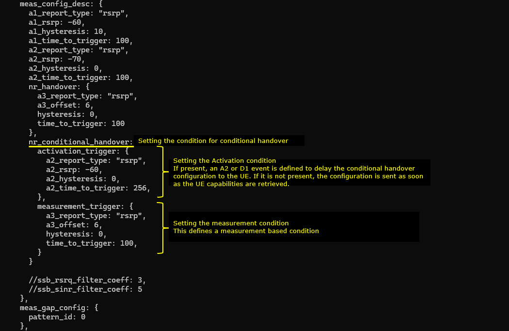
Then added measurement criteria before triggering Handover via the parameter meas_config_desc. Once this is configured, UE should report appropriate meausrement report for gNB to trigger handover. (

Now let's look into UEsim(DUT) configuration. (
N_ANTENNA_DL is set to 2 for 2x2 MIMO. TDD is set to 1 indicating this is TDD and CELL_BANDWIDTH is set to 20. Basically all of these configuration should match the configuration in gNB(Callbox).

The first cell(rf_port 0) is configured to match all the physical layer parameters to the first cell of gNB(Callbox) configuration. Then the second cell(rf_port 1) is configured to match all the physical layer parameters to the second cell of gNB(Callbox) configuration.
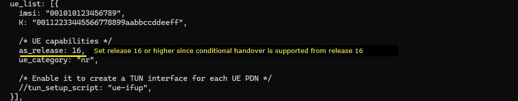
Since Conditional Handover is the refature of release 16 and onwords, you need to set as_release same as (or higher than) 16. Other part of UE configuration is same as default ue-nr-sa. As long as imsi, K matches any nr UE configuration would be OK.
Perform the test
Start LTE service and check basic cell configuration. Any cell configuration is OK as long as they are all NR cell. (


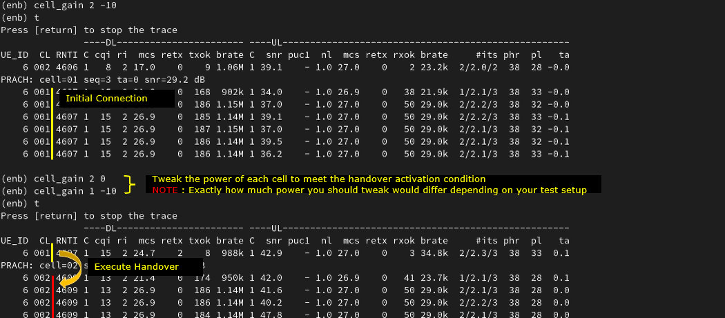
Adjust cell power. I used cell_gain command here instead of tx_gain because tx_gain changes broadcasting reference cell power in SIB message and UE may behave unexpectedly due to the SIB changes.
You should see the change of cell in 't' output if Handover performs properly.
Log Analysis
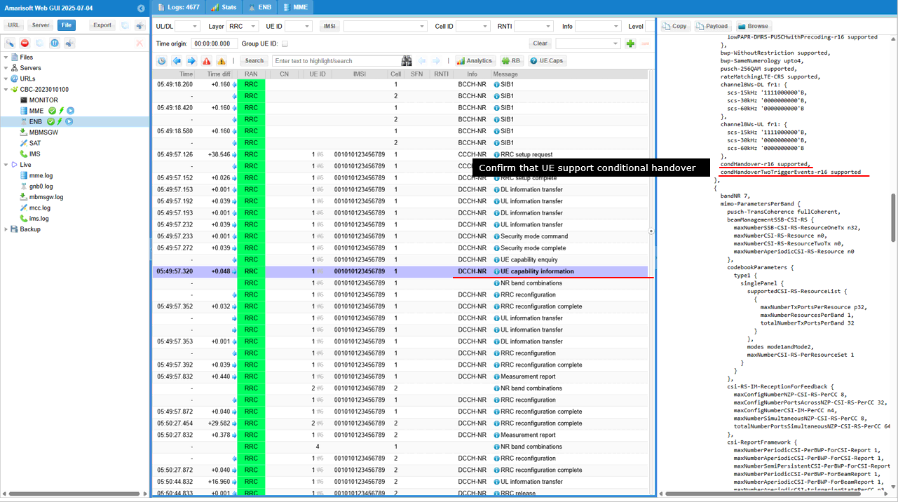
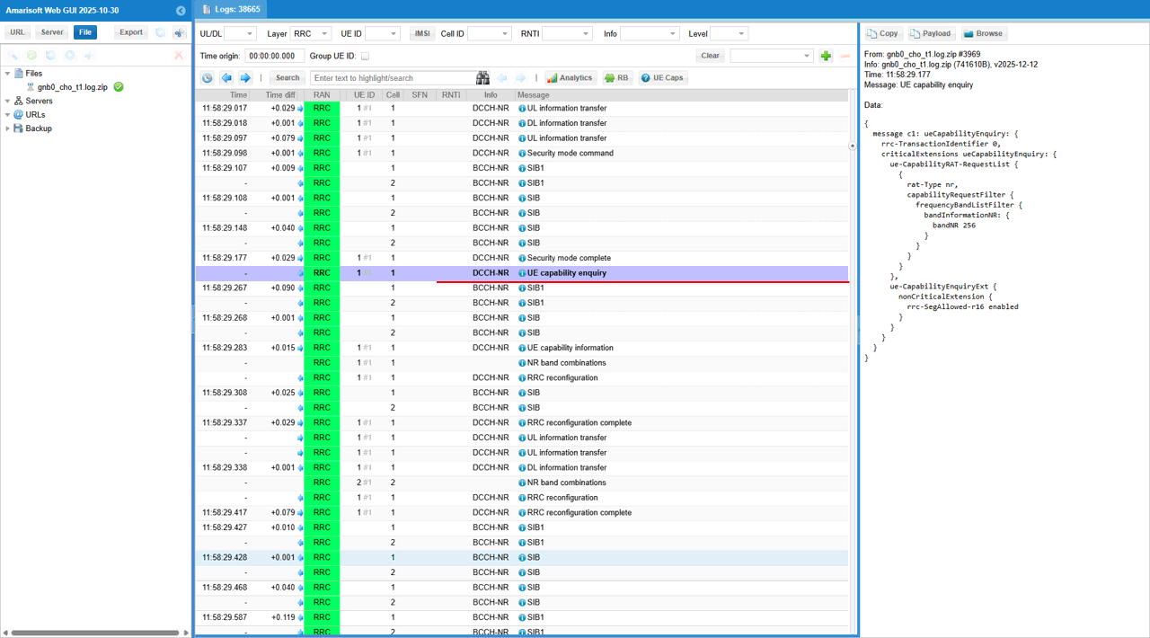
gNB sends UE Capability Enquiry to request the UE�s supported NR capabilities for the test bands. The enquiry specifically asks for band n3 and band n7, with rrc-SegAllowed-r16 enabled to permit segmented capability responses. This allows the gNB to efficiently gather only the relevant NR capability information from the UE before proceeding to RRC Reconfiguration
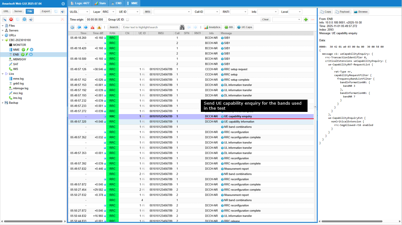
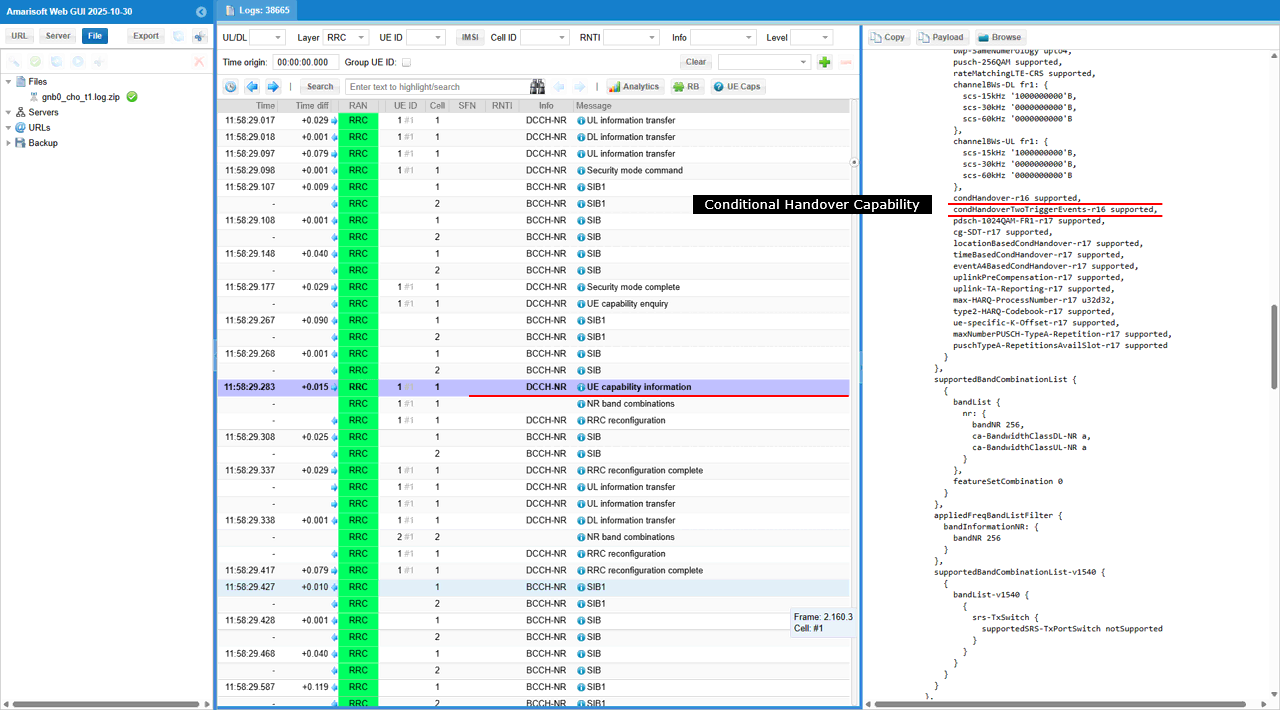
UE sends UE Capability Information to report its supported NR features in response to the earlier enquiry from the gNB. In this message, the UE declares condHandover-r16 supported and condHandoverTwoTriggerEvents-r16 supported, confirming that it can handle Release-16 Conditional Handover procedures. This capability allows the gNB to configure handover conditions in advance and trigger them automatically based on measured events.
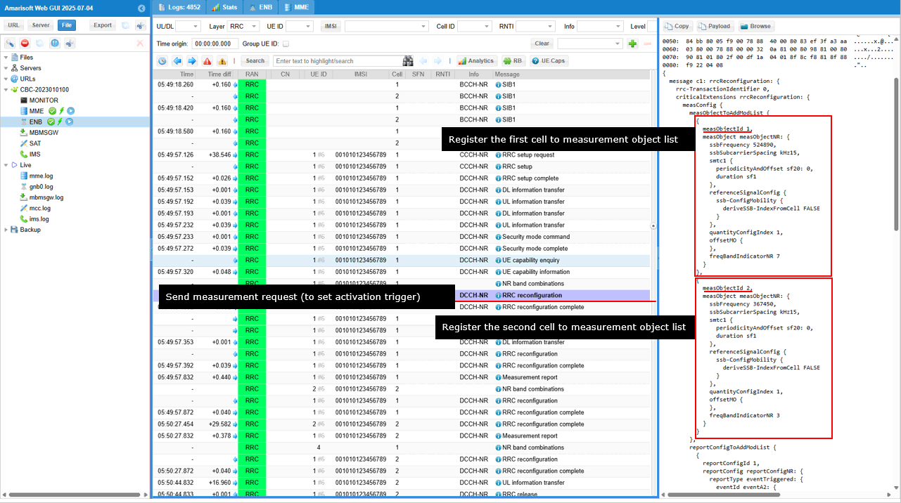
gNB sends RRC Reconfiguration to configure measurement objects as part of Handover preparation. In this message, the gNB adds two NR measurement objects: measObjectId 1 with ssbFrequency 524000 (ARFCN) corresponding to band n7, and measObjectId 2 with ssbFrequency 367450 (ARFCN) corresponding to band n3. Each measurement object defines subcarrier spacing, SSB configuration, and reference signal parameters. This configuration enables the UE to measure signal quality on both target frequencies, allowing the gNB to use the results later as triggers for Conditional Handover activation.
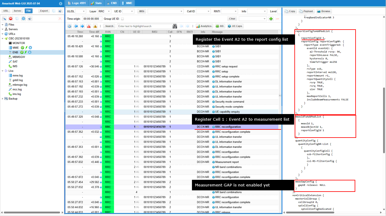
In the same RRC Reconfiguration message is an event-based reporting configuration. In this message, reportConfigId 1 is defined for Event A2, which is triggered when the serving cell RSRP falls below the threshold (rsrp < 96 dBm). The configuration specifies a reporting interval of 120 ms and a time-to-trigger of 256 ms. The gNB associates this report configuration with measObjectId 1 under measId 1, enabling the UE to start monitoring the serving cell�s degradation condition. The measurementGapConfig is marked as NULL, indicating that measurement gaps are not yet enabled at this stage.
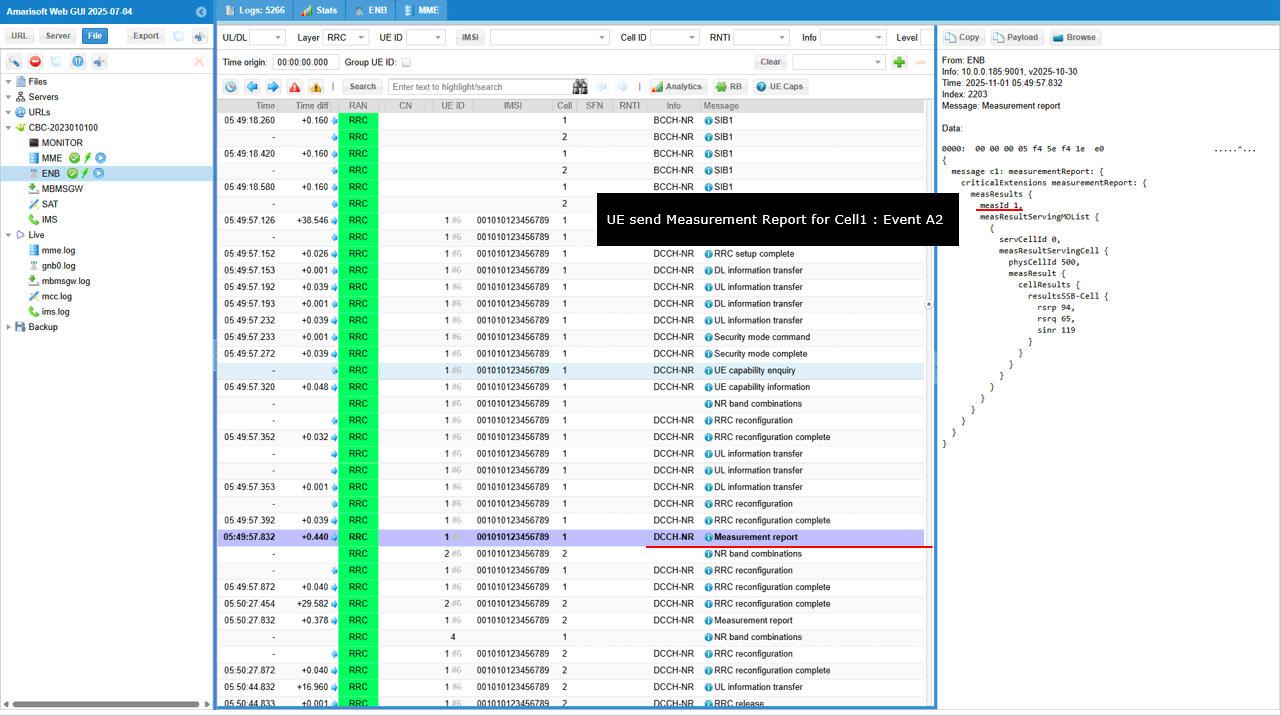
UE sends Measurement Report to the gNB for Cell 1, corresponding to Event A2. This report is triggered when the serving cell quality drops below the configured threshold. The report includes measId 1 and serving cell measurements: RSRP = 94, RSRQ = 65, and SINR = 119. These values indicate that the UE detected degraded signal conditions, prompting the gNB to proceed with Conditional Handover preparation.
The same RRC Reconfiguration configures Event A3 reporting and enable measurement gaps for inter-frequency monitoring. The message defines reportConfigId 1 for Event A3, which is triggered when a neighbor cell becomes better than the serving cell by 6 dB (a3-Offset = 6). The reporting type is condTriggerConfig-r16, indicating it will be used for Conditional Handover triggering. The gNB links measObjectId 2 with this event through measId 1, instructing the UE to start monitoring the second frequency layer. The measurementGapConfig is now activated with gapOffset = 16, mgta = 0, and mgl = 56, allowing the UE to measure neighboring frequencies without interrupting ongoing data transmission
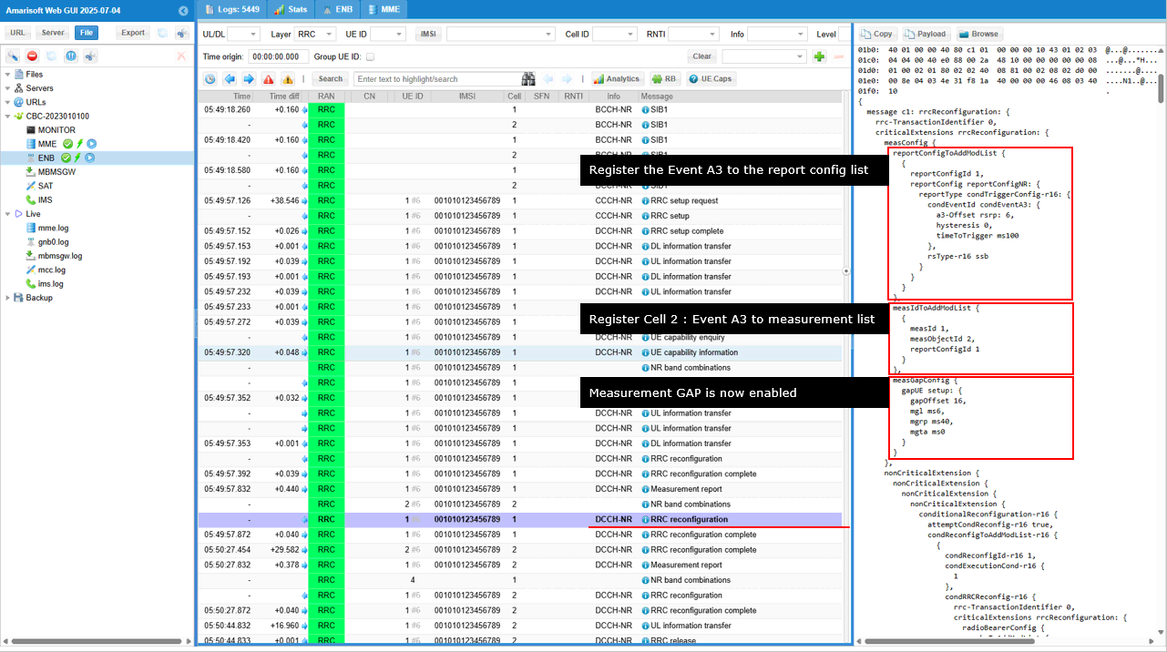
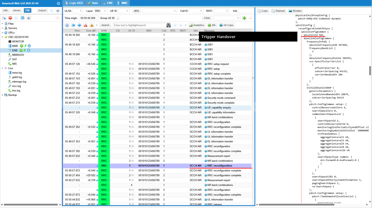
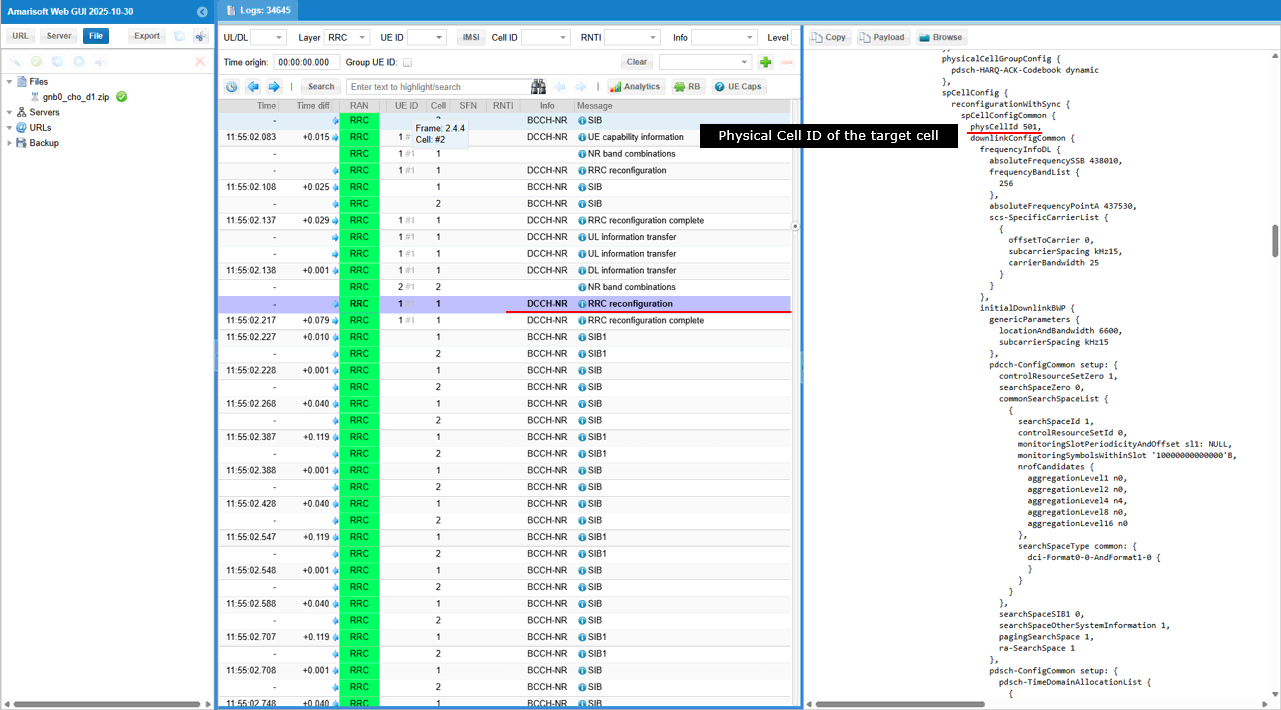
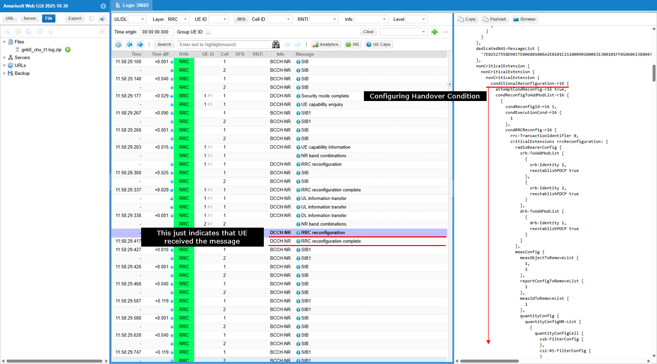
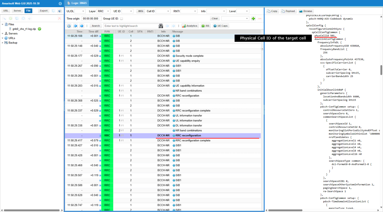
In the same message is the Conditional Handover configuration to the UE. In this message, the field conditionalReconfiguration-r16 is included with attemptCondReconfig-r16 = true, indicating that the UE is instructed to store and prepare conditional handover parameters without immediately executing the handover. The message also contains condReconfigToAddModList-r16, which specifies the configuration set for later execution when the defined trigger condition is met. This marks the transition from measurement-based preparation to actual CHO configuration, enabling the UE to perform autonomous handover once the event criteria are satisfied.
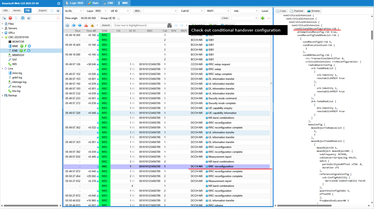
The configuration includes parameters such as physCellId = 501 and absoluteFrequencySSB = 367450 (ARFCN), indicating that the UE is expected to move to the target cell operating on this frequency when the condition is met.
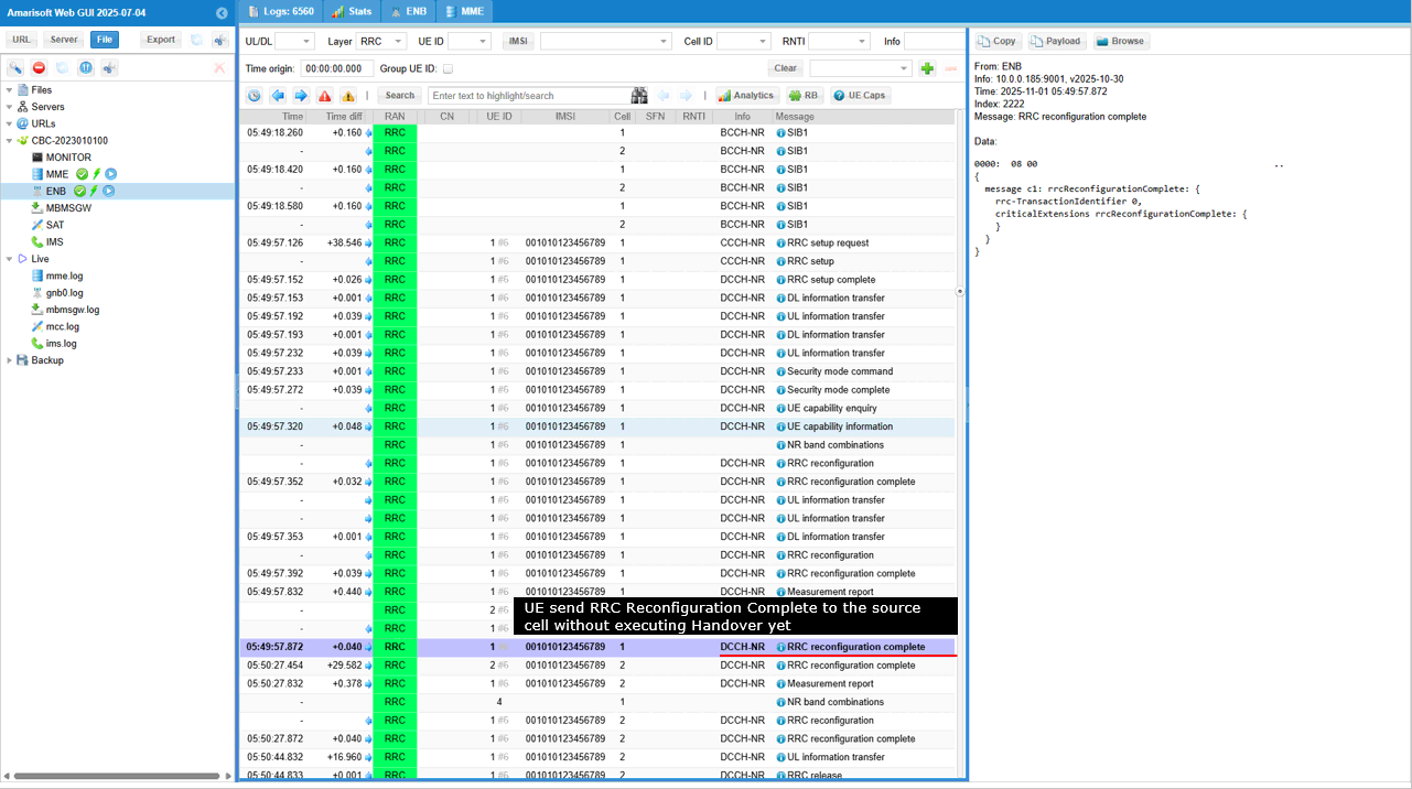
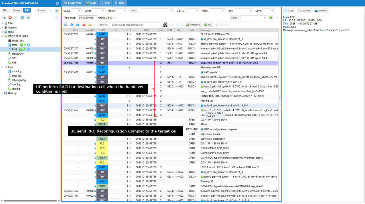
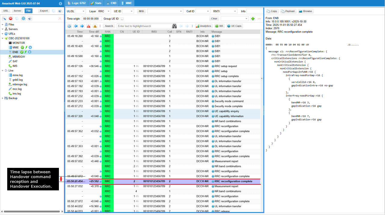
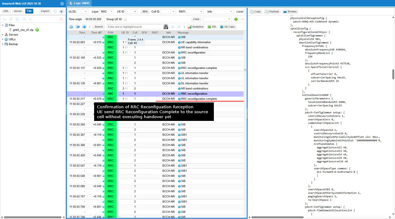
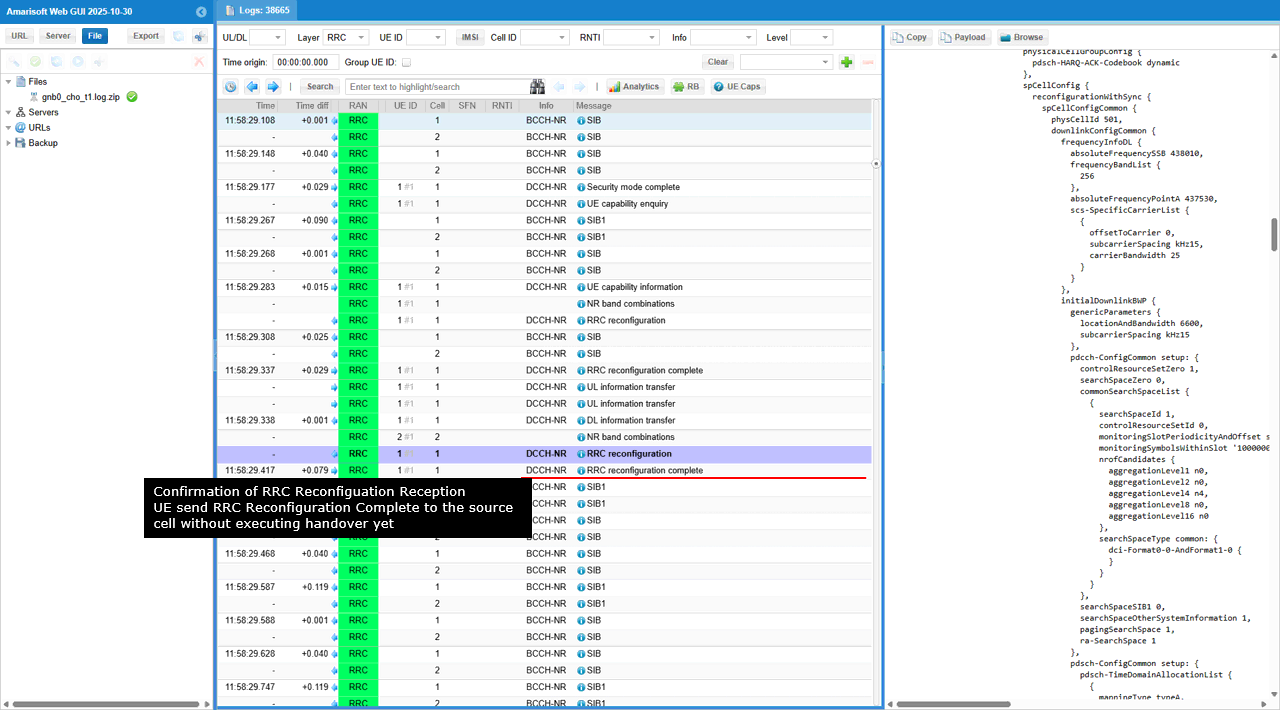
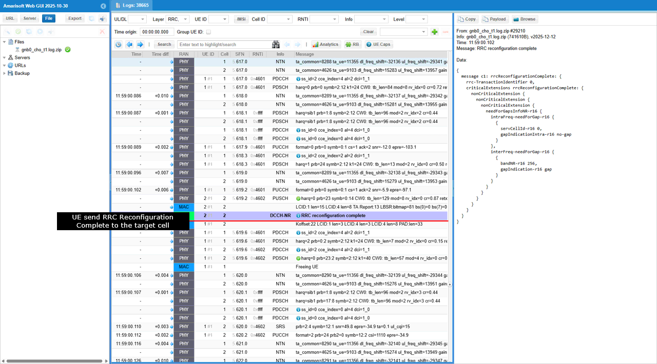
UE sends RRC Reconfiguration Complete to the source gNB, confirming successful reception of the conditional handover configuration without actually executing the handover yet. This message indicates that the UE has stored the conditional handover command and is ready to trigger the move once the predefined condition (e.g., Event A3 threshold) is met. At this stage, the UE remains connected to the source cell and continues normal operation while monitoring measurements for the trigger event.
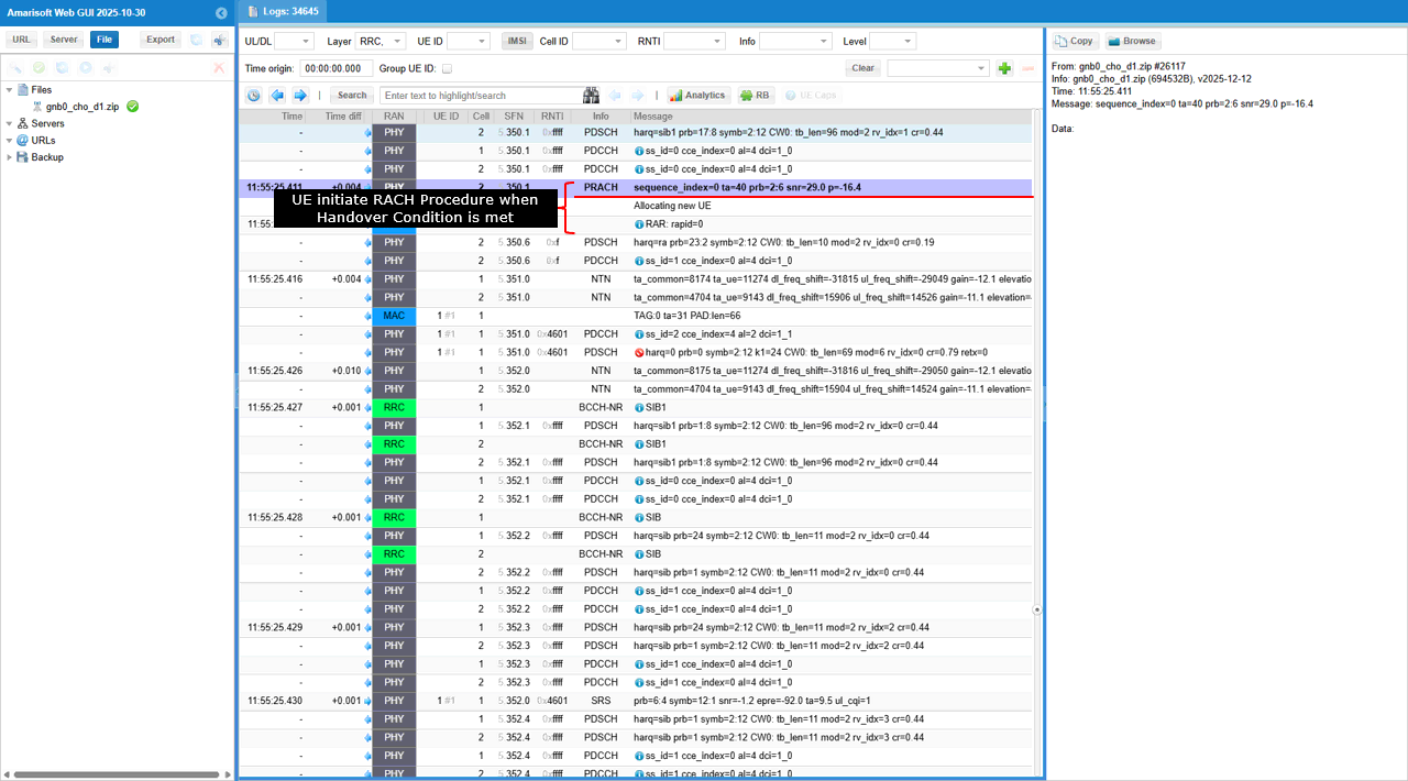
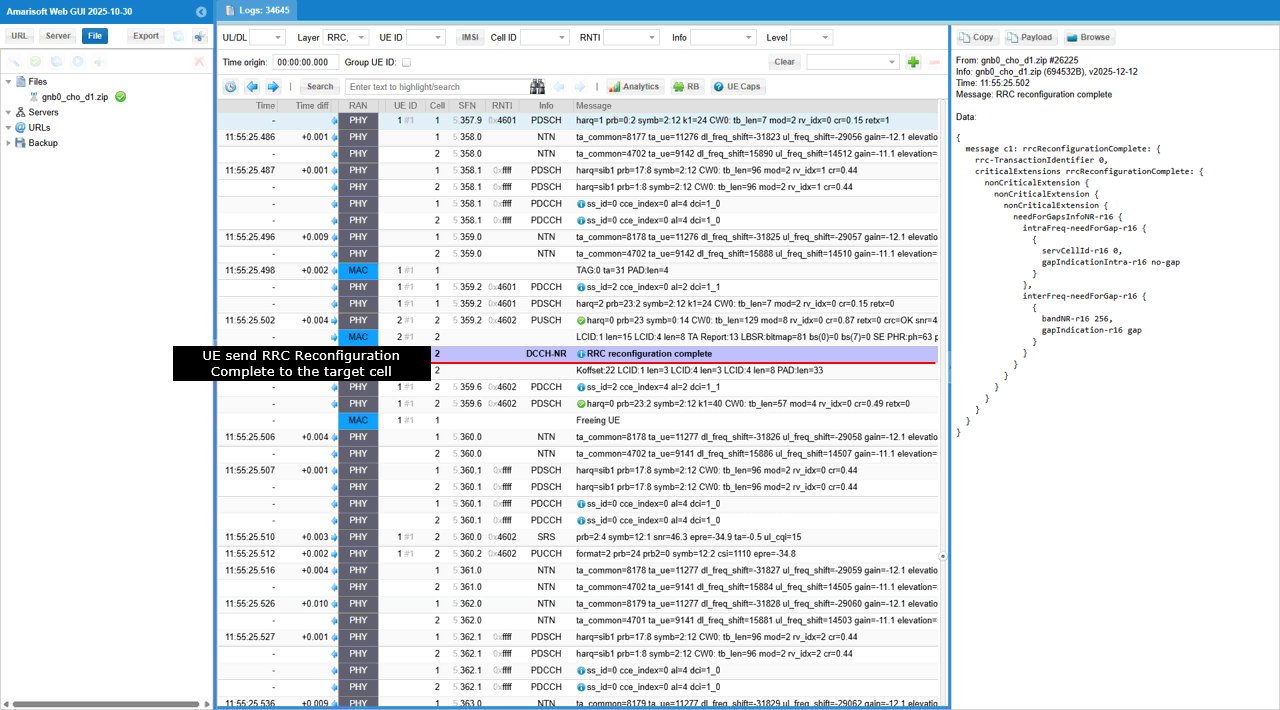
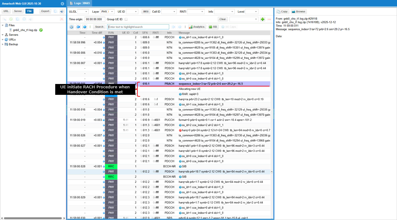
UE performs RACH on the target cell once the conditional handover trigger condition is satisfied. The PRACH transmission is initiated to establish uplink synchronization with the target gNB. After receiving the RAR (Random Access Response) and completing the contention resolution, the UE proceeds to send RRC Reconfiguration Complete to the target gNB. This confirms successful execution of the conditional handover and activation of the target cell configuration. From this point, the UE operates under the target gNB while the data path is switched from the source to the destination.
Just for your reference, I put some important UE side log to show what's happending within UE for conditional handover.
UE recieves RRC reconfiguration for conditional handover.
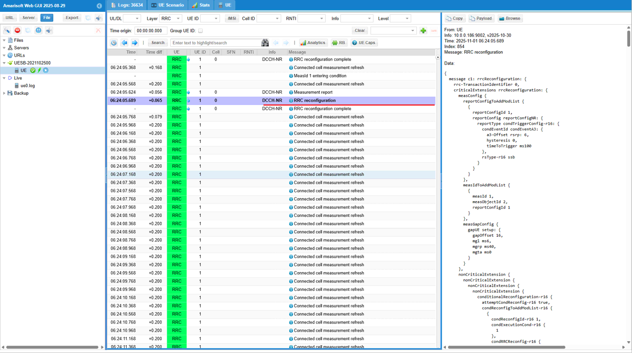
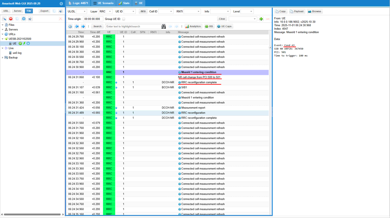
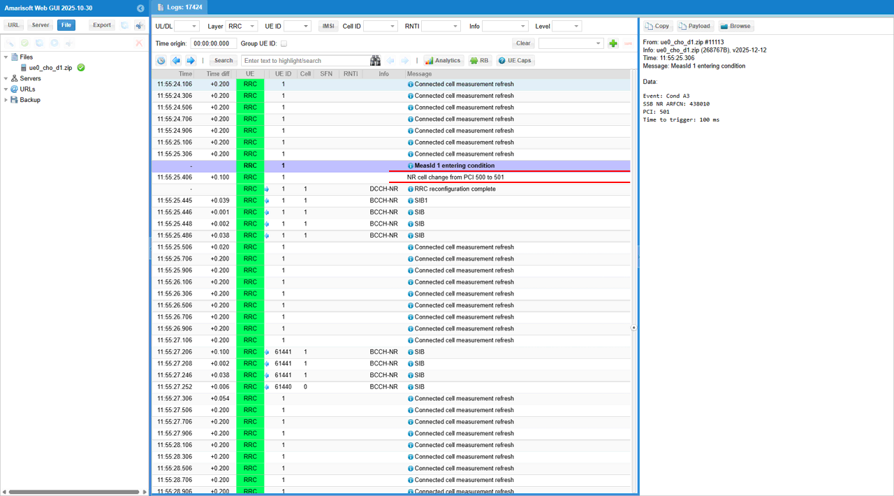
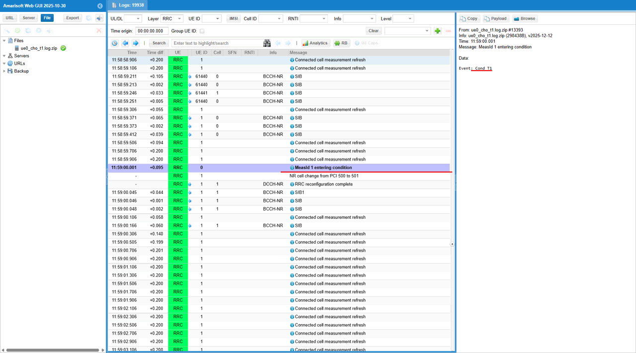
After receiving the RRC Reconfiguration for Conditional Handover, the UE begins continuous measurement reporting to evaluate the triggering condition. The log shows Connected cell measurement refresh entries followed by MeasId 1 entering condition, which corresponds to Event A3.
At this moment, the UE measures two cells:
- Cell 1 with ARFCN 524890 (PCI 500) shows RSRP -72.1 dBm.
- Cell 2 with ARFCN 367450 (PCI 501) shows RSRP -65.6 dBm.
Since the neighbor cell (PCI 501) becomes stronger than the serving cell by approximately 6 dB, the Event A3 condition is satisfied. This triggers the UE to start the Conditional Handover procedure � performing RACH toward the target cell and sending RRC Reconfiguration Complete once the handover is successfully executed.
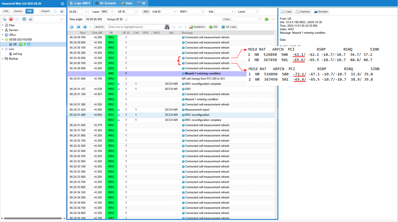
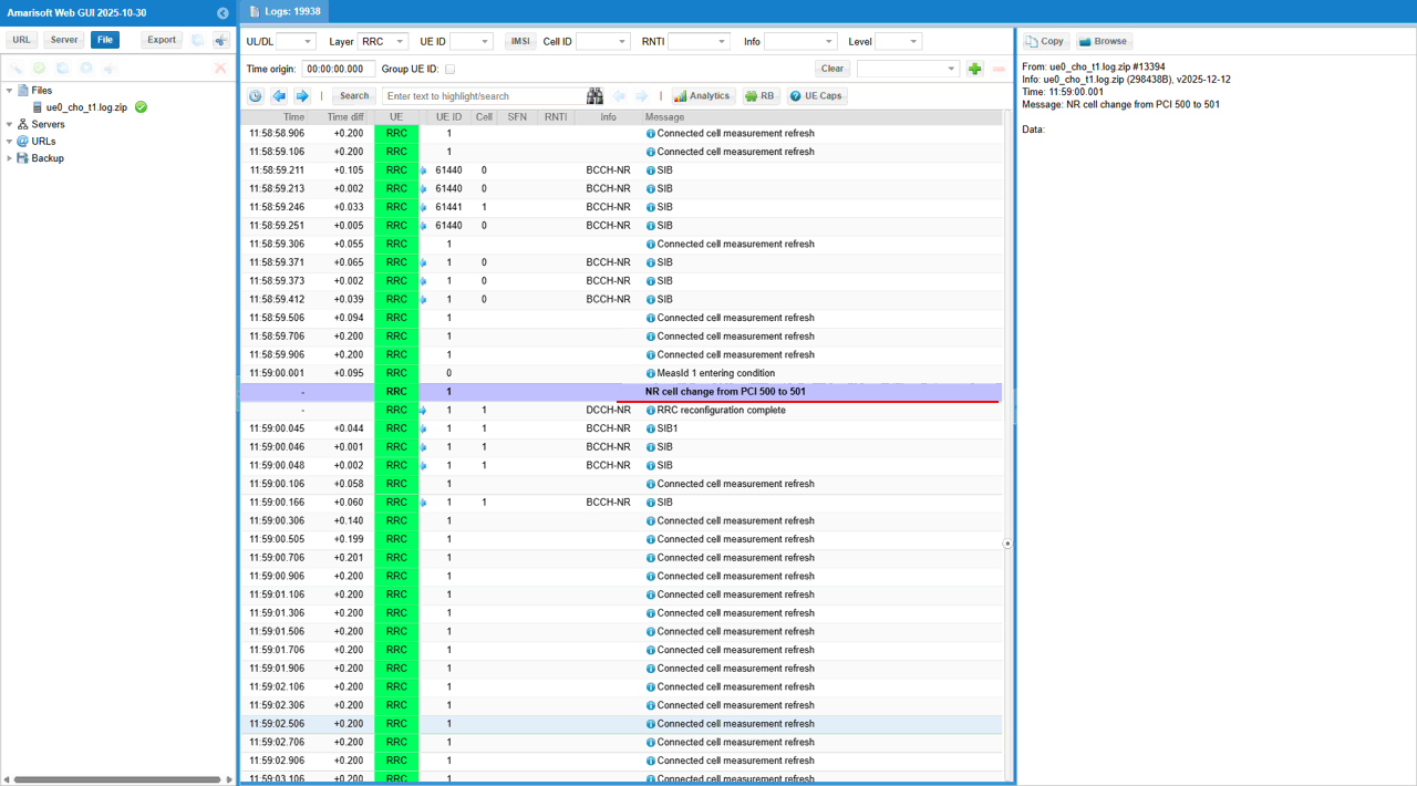
Following screen shows that the UE detects that MeasId 1 (Event A3) has entered the triggering condition. The measurement corresponds to neighbor cell PCI 501 on ARFCN 367450, where the RSRP has become better than the serving cell PCI 500 by approximately 6 dB, satisfying the configured A3-Offset.
Upon meeting this condition, the UE logs �MeasId 1 entering condition� with a timeToTrigger = 100 ms, meaning the UE will confirm the event if the condition persists for that duration. Immediately after this, the UE reports cell change from PCI 500 to PCI 501 and executes Conditional Handover, completing the process by sending RRC Reconfiguration Complete to the new target cell.
Test 2 : NTN SA Inter Frequency Conditional Handover - with Event D1
In this test, I will show on a scenario to trigger an handover between two NTN cells with the Event D1.
Configuration
I used the gnb-sa-ntn-multi-cell_d1.cfg which is copied and modified from gnb-sa.cfg

I also used mme-ims.cfg as it is.
I used the ue-nr-ntn-multi-cell_d1.cfg which is copied and modified from ue-nr-sa.cfg
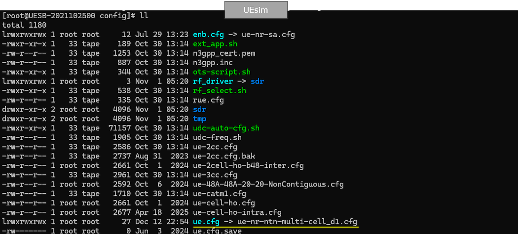
Configure gnb-sa-ntn-multi-cell_d1.cfg as below.
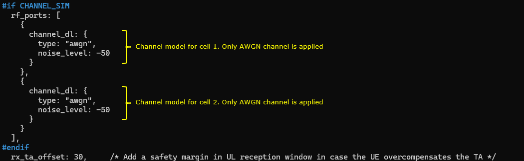
This configuration sets NTN_MODE=2 to run a LEO NTN scenario, with NR_BANDWIDTH=5 reflecting the reduced bandwidth used in NTN bands. It uses a simple SISO setup (N_ANTENNA_DL=1, N_ANTENNA_UL=1), enables satellite channel emulation via CHANNEL_SIM=1, and activates conditional handover with CHO=1.

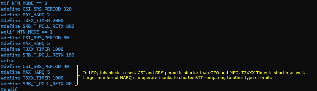
This configuration selects different timing and reliability parameters based on the NTN orbit type. For LEO (NTN_MODE=2), shorter CSI/SRS periods (CSI_SRS_PERIOD=40) are used to track fast channel variation caused by satellite motion. The T3xx timer is also shorter (T3XX_TIMER=1000) to support quicker mobility and recovery actions. A larger HARQ capability (MAX_HARQ=5) is feasible in LEO due to its shorter RTT compared to GEO and MEO.
Make it sure that you have enough number of sdr cards for this test in rf_driver. In this test, I am using only 2 cell with SISO, so dev0, dev1 would be good enough.
This configuration enables the channel simulator and applies an AWGN-only downlink channel to both NTN cells. Each cell uses the same noise setting (noise_level = -50), so the handover test focuses on NTN mobility and control behavior rather than channel fading or beam dynamics. This helps isolate handover logic under simplified satellite channel conditions.
This configuration defines an NR NTN serving cell operating in band 256 with 15 kHz SCS and a shortened SSB periodicity (ssb_period = 5) to improve UE timing tracking in LEO. NTN-specific parameters include the initial satellite elevation offset (default_elevation_offset = 55) and a reference Earth location used by the quasi-Earth-fixed NTN model. A neighbour cell is also defined and marked as a conditional handover target, allowing it to be prepared in advance as the satellite coverage moves

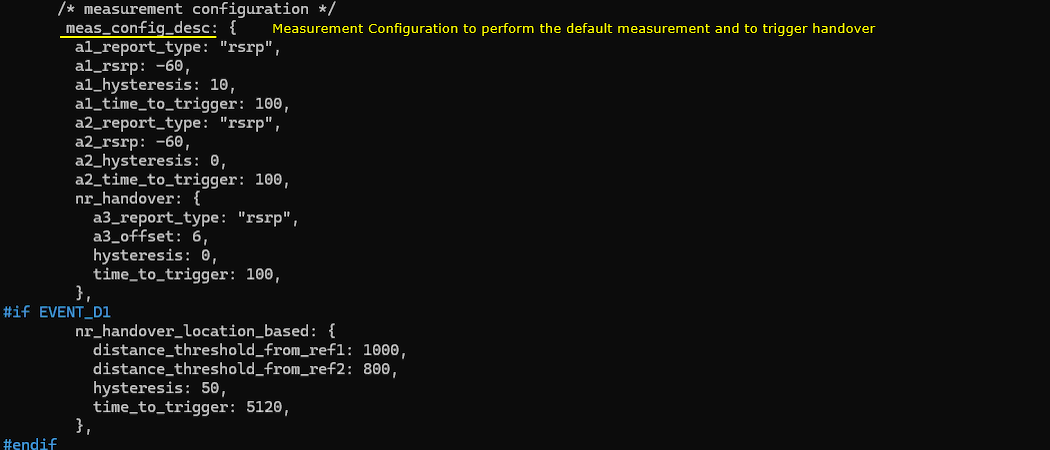
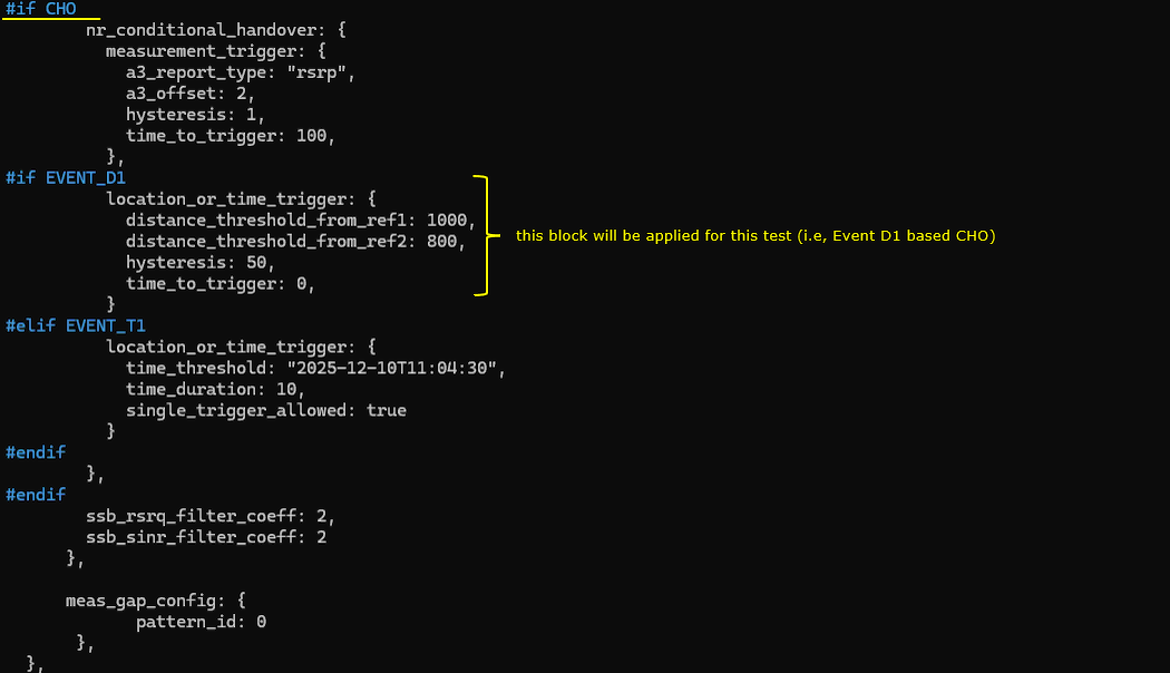
This part configures NTN mobility measurements and handover triggers.For NTN-specific behavior, EVENT_D1 enables a location-based handover trigger, using distance thresholds (distance_threshold_from_ref1=1000, distance_threshold_from_ref2=800) with additional hysteresis=50. When CHO is enabled, the neighbour is prepared as a conditional handover target, and in this test the CHO execution is also driven by the same Event D1 distance trigger (time_to_trigger=0 in the CHO block), which fits NTN where handover timing can be predicted from satellite/beam geometry rather than only radio level changes.
I added neighbour cell list(ncell_list) to the configuration of the second cell and add the first cell(n_id_cell:1) as the neighbour cell and set conditional_handover_target : true to enable conditional handover for the target cell.
This configuration defines the second NTN cell, mapped to rf_port=1, operating in band 256 with 15 kHz SCS and a short SSB periodicity (ssb_period=5) suitable for LEO tracking. The NTN parameters set a different initial satellite elevation offset (default_elevation_offset=-60) and a separate reference Earth location, representing a distinct satellite/beam geometry. This cell lists the first cell as its neighbour and is marked as a conditional handover target, enabling bidirectional NTN handover testing.

This configuration sets the default NR cell parameters, using NR_BANDWIDTH and the configured DL/UL antenna counts for the NTN cell. It schedules regular system information delivery, including SIB2 and SIB19, with si_periodicity=16 and a si_window_length=40. In the NTN context, SIB19 is explicitly included to provide the UE with NTN-specific information such as ephemeris data and timing advance�related parameters, which are essential for satellite-based mobility and handover.

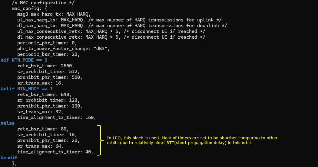
This MAC configuration adapts HARQ limits and uplink control timers according to the NTN orbit type. In the LEO case, shorter values are used for parameters such as retx_bsr_timer, sr_prohibit_timer, prohibit_phr_timer, and time_alignment_tx_timer, reflecting the shorter RTT and propagation delay compared to GEO and MEO. Higher sr_trans_max is also allowed, enabling more responsive uplink scheduling during fast LEO NTN mobility and handover scenarios.
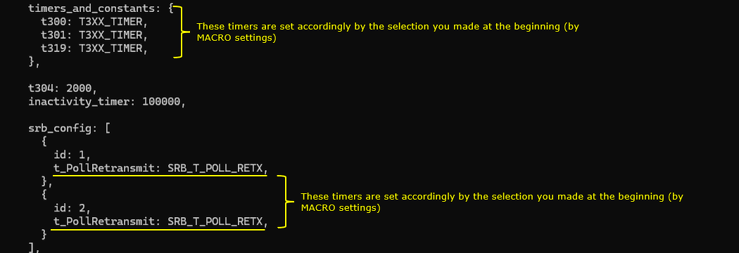
This configuration sets RRC timers and SRB retransmission behavior according to the selected NTN mode via predefined macros. Timers such as t300, t301, t319, and t_PollRetransmit are automatically scaled to match the orbit-dependent RTT characteristics. In the LEO NTN case, these values are shorter, enabling faster RRC recovery and signaling exchange during frequent cell and beam transitions.
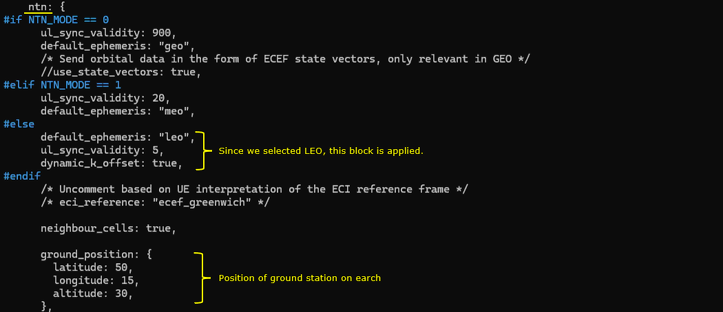
This NTN configuration selects LEO operation, using default_ephemeris="leo" and a short ul_sync_validity=5 to handle fast satellite movement. The parameter dynamic_k_offset is enabled, allowing UE-specific k_offset adjustment based on UE Timing Advance reports. This supports accurate uplink timing and more stable LEO NTN mobility and handover under rapidly changing satellite geometry. The ground_position parameter defines the geographical position of the eNB, which is used in transparent NTN mode to automatically compute NTA-Common, NTA-CommonDrift, and NTA-CommonDriftVariation, supporting accurate uplink timing and stable handover.
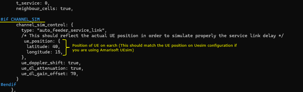
This configuration enables NTN channel simulation using type="auto_feeder_service_link", allowing the callbox to automatically model feeder and service link delays. The ue_position (latitude/longitude) defines the Earth-fixed UE location, which must match the UE simulator configuration to correctly compute propagation delay, Doppler shift, and link geometry. With ue_doppler_shift and ue_dl_attenuation enabled, the setup reflects LEO-specific Doppler and path loss, supporting realistic NTN mobility and handover behavior.
Now let's look into UEsim(DUT) configuration. (
In ue-nr-ntn-multi-cell_d1.cfg ,N_ANTENNA_DL is set to 1 for SISO and channel bandwidth of the cell (CELL_BANDWIDTH) is set to 5 Mhz.
![]()
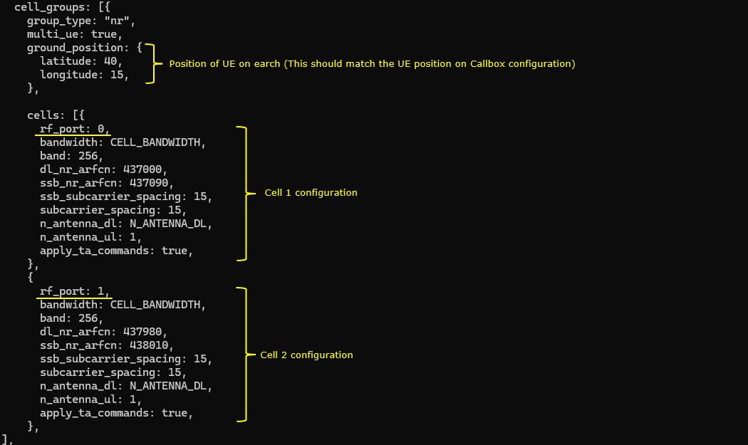
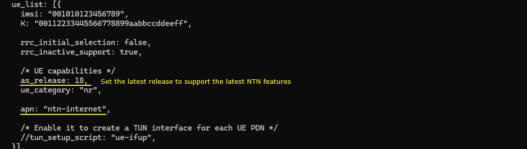
This UEsim configuration defines an NR cell group for an NTN scenario, with ground_position specifying the UE�s Earth-fixed location, which must match the callbox configuration to ensure consistent NTN geometry. Two NTN cells are configured on different rf_ports, both operating in band 256 with 15 kHz SCS. The parameter apply_ta_commands enables the UE to apply Timing Advance commands received from the network in multiple-UE mode. In an NR NTN scenario, this is important to correctly track uplink timing variations caused by satellite movement
Since Conditional Handover is the refature of release 16 and onwords, you need to set as_release same as (or higher than) 16. With as_release=18 the latest NTN and CHO features and behavior are enabled
Perform the test
Start LTE service and check basic cell configuration. Any cell configuration is OK as long as they are all NR cell. (
This output confirms that two NR NTN cells are active under the same gNB, both operating in band n256 with 5 MHz bandwidth and 15 kHz SCS, which is typical for NTN deployments. Each cell is mapped to a different ARFCN and PCI (cell 0x001 and 0x002), allowing them to act as distinct NTN beams/cells for handover testing


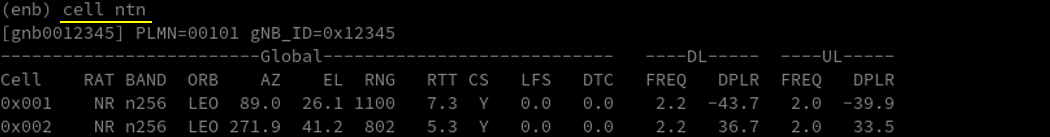
This output of 'cell ntn' shows NTN-specific runtime status for two LEO NR cells. For each cell, the system reports the satellite geometry (azimuth AZ, elevation EL), slant range RNG, and round-trip time RTT, confirming different beam/satellite positions relative to the UE. The presence of non-zero Doppler (DPLR) on DL and UL highlights typical LEO Doppler behavior, which is a key driver for NTN handover between moving beams/cells.
Adjust cell power. I used cell_gain command here instead of tx_gain because tx_gain changes broadcasting reference cell power in SIB message and UE may behave unexpectedly due to the SIB changes.
You should see the change of cell in 't' output if Handover performs properly.
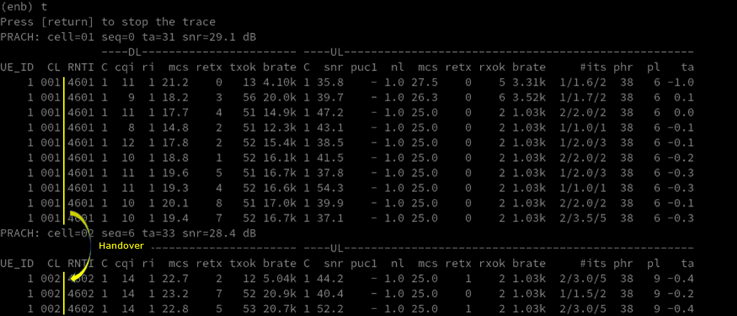
This t trace output shows a successful NTN cell handover. In the upper part of the trace, the UE is scheduled on cell 01, and a PRACH on cell 02 appears (PRACH: cell=02), indicating handover execution. Immediately after that point, the CL field changes from 001 to 002, confirming that the UE has moved to the target NTN cell/beam.
Log Analysis
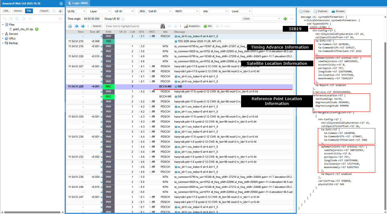
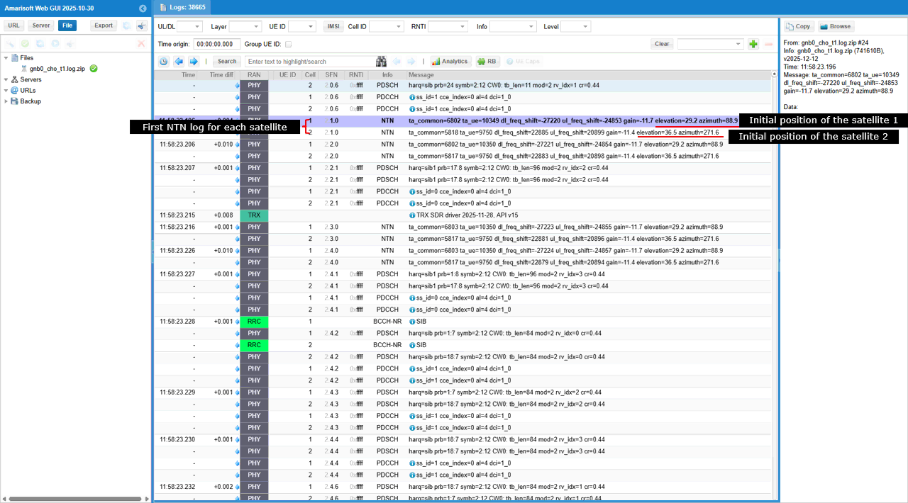
The first NTN log lines shows the initial NTN context establishment for two LEO satellites (or beams). The first NTN PHY log entry per cell reports ta_common, ul_freq_shift, dl_freq_shift, along with elevation and azimuth, which together describe the initial satellite geometry and Doppler state seen by the UE.
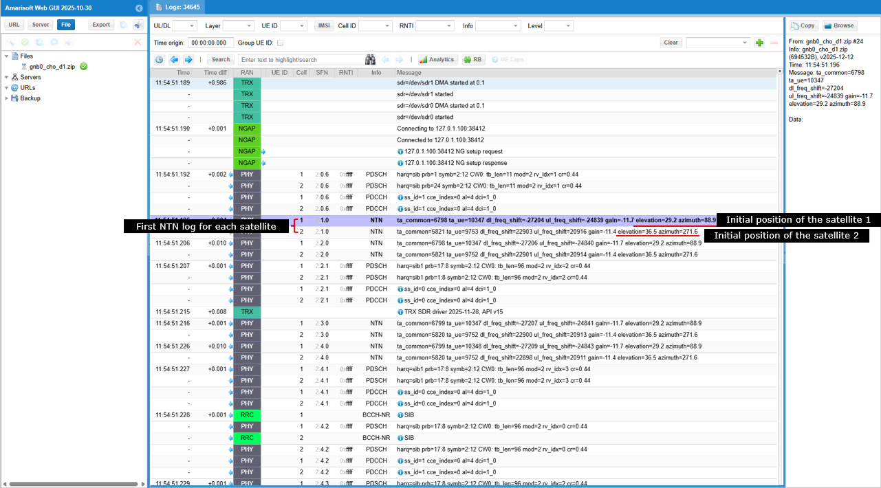
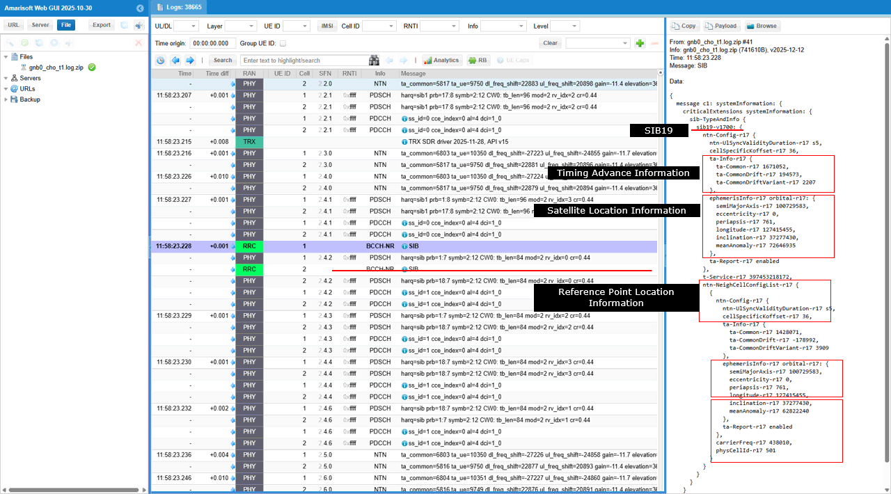
Then check out SIB19 transmission, which is a key NTN-specific step. The UE receives Timing Advance information (ta-Common, ta-CommonDrift, ta-CommonDriftVariation) used to compensate for satellite motion�induced delay changes in transparent (bent-pipe) NTN mode. It also includes satellite orbital parameters (ephemeris), giving the UE the satellite�s position and motion needed for Doppler and timing prediction.
In addition, the reference point location (Earth-fixed coordinates) is provided, which the UE uses together with ephemeris to derive the NTN geometry. From an NTN handover perspective, correct SIB19 reception confirms that the UE has all required geometry, timing, and drift information to perform location-aware and predictive handover between moving LEO cells.
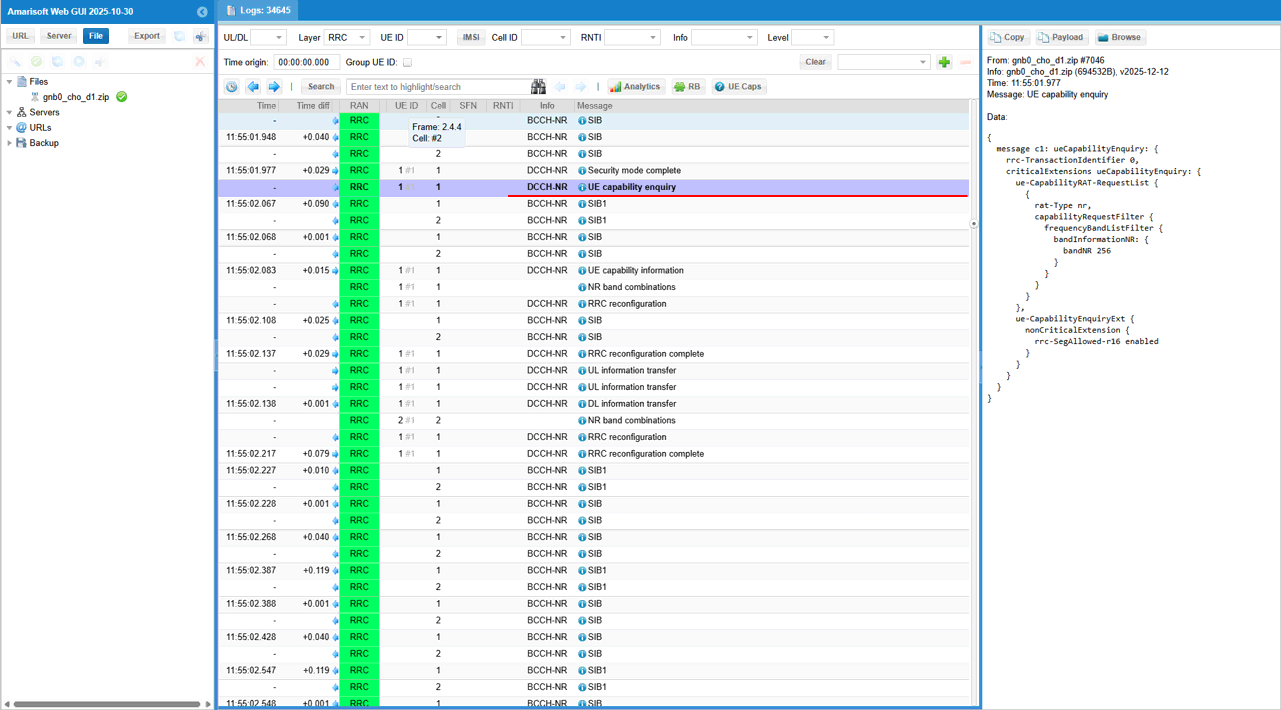
gNB sends UE Capability Enquiry to request the UE�s supported NR capabilities for the test bands. The enquiry specifically asks for band n256, with rrc-SegAllowed-r16 enabled to permit segmented capability responses. This allows the gNB to efficiently gather only the relevant NR capability information from the UE before proceeding to RRC Reconfiguration
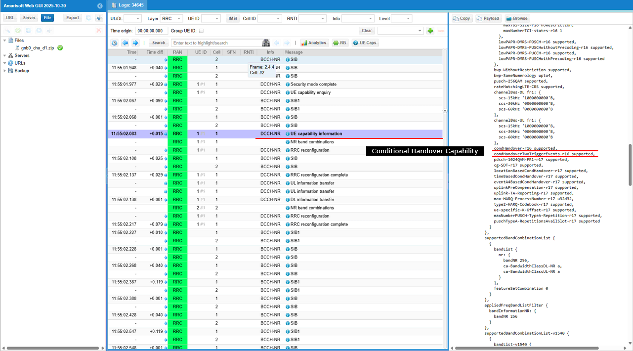
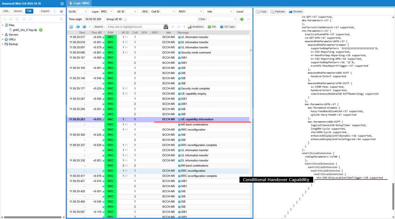
UE sends UE Capability Information message. In this message, the UE reports support for Conditional Handover through the IEs condHandoverTriggerEvents-r16 and condHandover-r17-supported, indicating support for both event-based and enhanced CHO mechanisms. This confirms that the UE can handle predictive NTN handover, which is essential for LEO beam-to-beam or satellite-to-satellite handover driven by satellite geometry rather than only radio-level measurements.
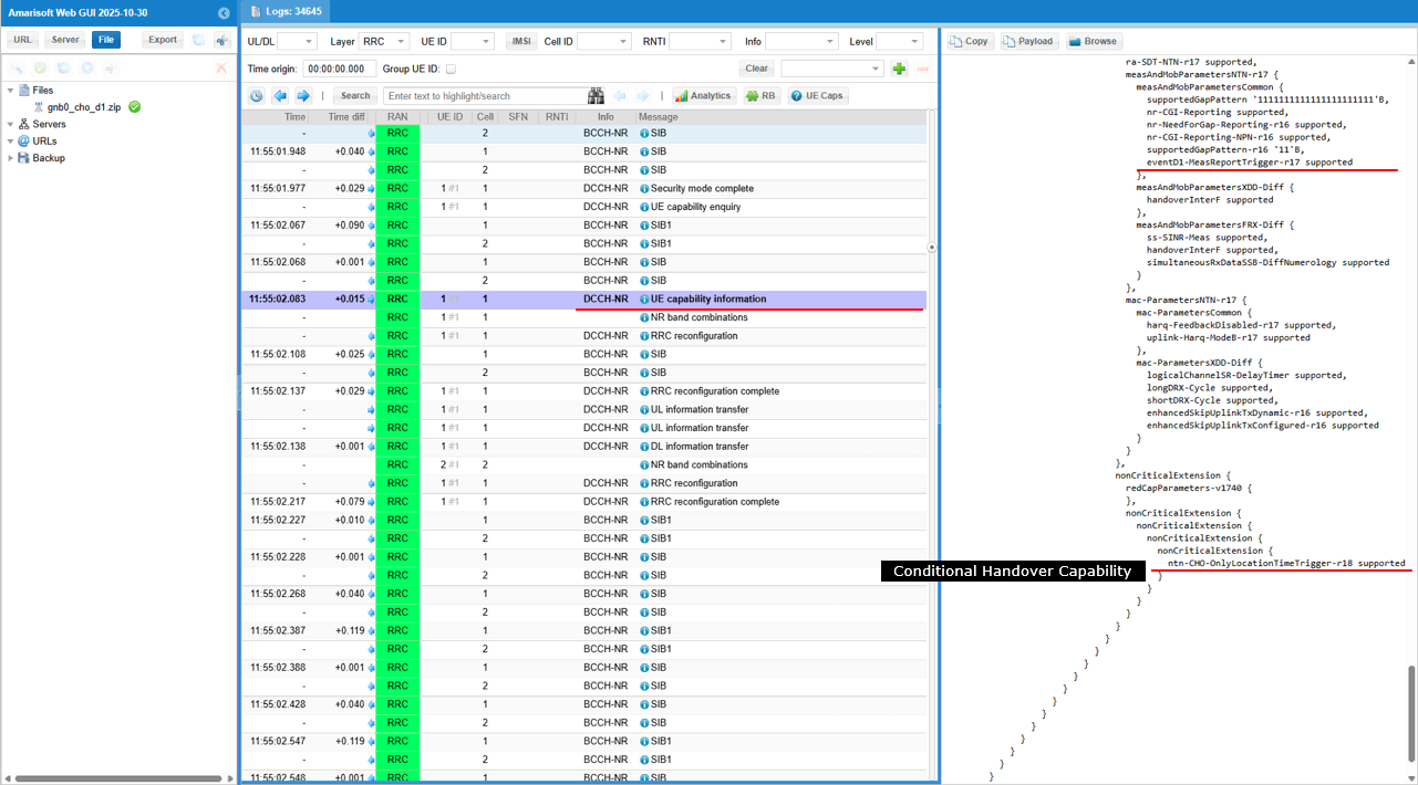
In this same message, the UE explicitly reports NTN-specific Conditional Handover support. In particular, the highlighted IE eventD1-MeasReportTrigger-r17-supported indicates support for Event D1�based measurement reporting, which is designed for location- and geometry-driven handover in NTN. In addition, the IE ntn-CHO-OnlyLocationTimeTrigger-r18-supported confirms support for pure location/time�based Conditional Handover, where handover execution can rely on predicted satellite movement rather than radio measurements alone. Together, these IEs confirm that the UE can perform predictive CHO in LEO NTN, which is essential for beam-to-beam or satellite-to-satellite handover under fast-moving satellite geometry.
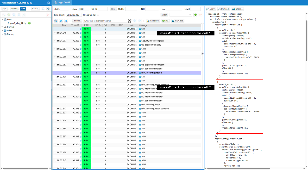
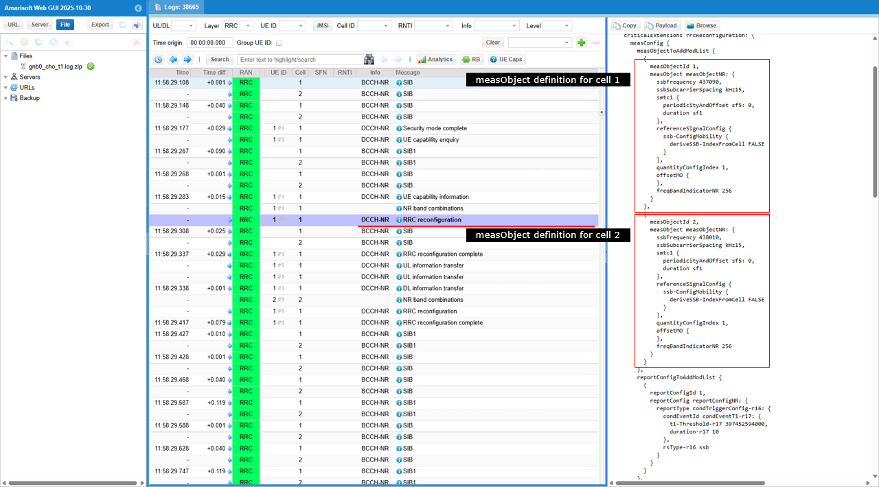
gNB sends RRC Reconfiguration . In this message, two measurement objects are configured, one for cell 1 and one for cell 2, each defined as a NR SSB-based measurement object. For each cell, the SSB frequency (ssbFrequency), SSB subcarrier spacing (ssbSubcarrierSpacing), SSB periodicity, and reference signal configuration are provided.
From an NTN perspective, this explicitly prepares the UE to measure SSBs from multiple NTN cells/beams in parallel, which is required for beam-to-beam or satellite-to-satellite handover. These measurement objects are the basis for triggering A3 / Event D1 / conditional handover decisions as the satellite geometry evolves.
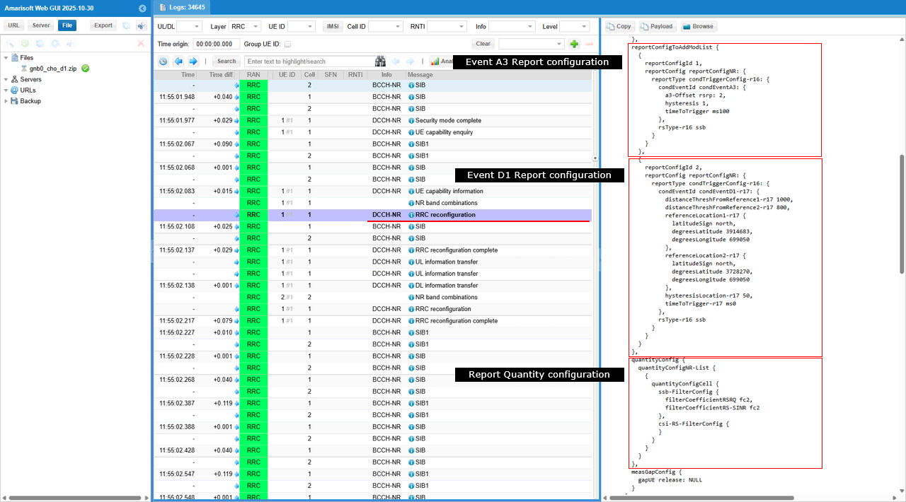
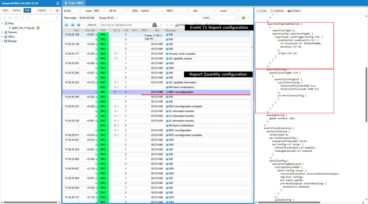
The highlighted IEs shown below configure both A3 (radio-based) and D1 (location-based) measurement reporting, which is essential for predictive conditional handover in LEO NTN scenarios. The first block is Event A3 report configuration, using the IE reportType = reportCGITriggerConfig-r16 / condEventCondNR-Config with a3-Offset and timeToTrigger, enabling signal-strength�based handover triggering for the neighbour cell. The second block is Event D1 report configuration, using the IE condEventD1-r17, which includes distanceThreshFromReference1-r17, distanceThreshFromReference2-r17, referenceLocation1-r17, referenceLocation2-r17, and timeToTrigger-r17. This configures NTN-specific, location-based handover triggering driven by satellite/beam geometry. The third block is the report quantity configuration, using quantityConfigNR-List with ssb-FilterConfig and csi-rs-FilterConfig, defining filtering behavior for reported measurements.
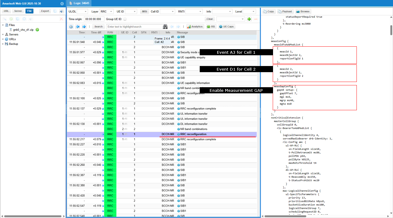
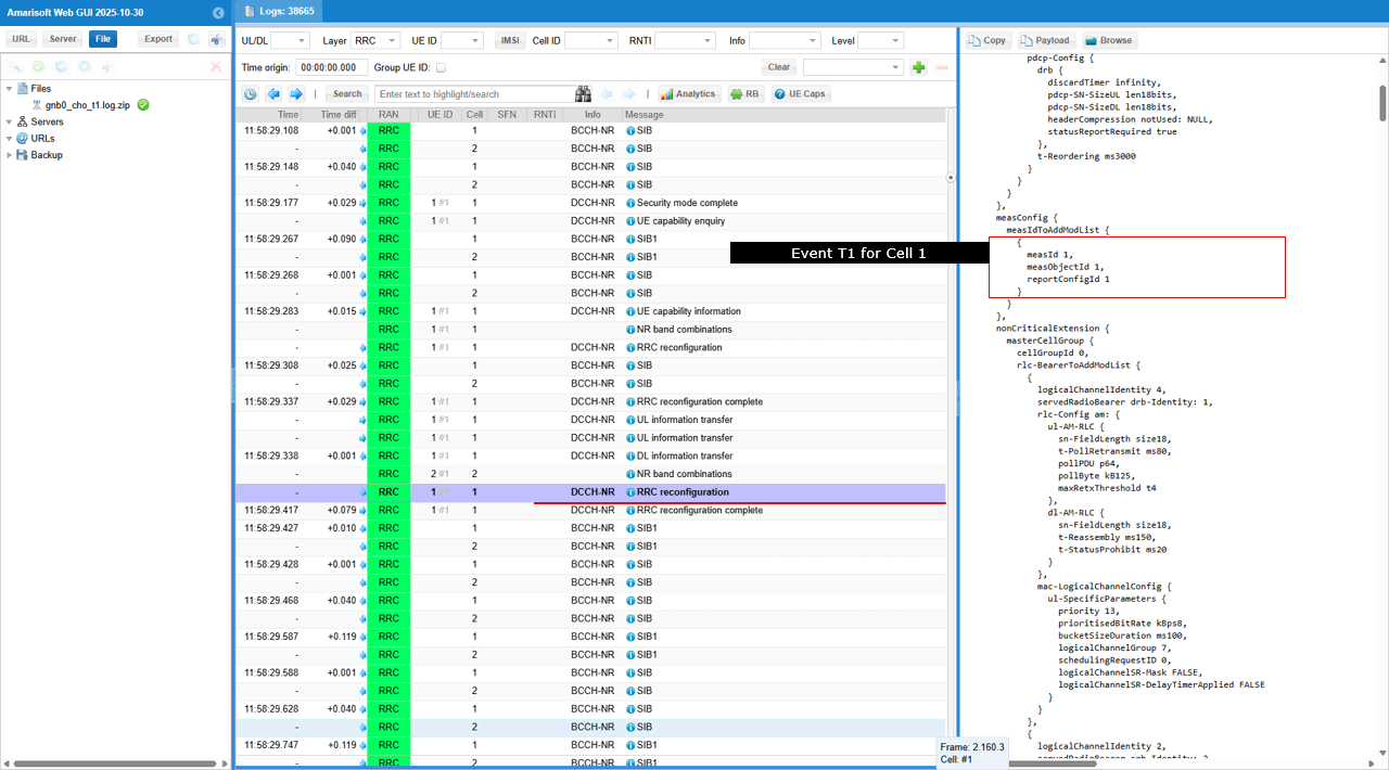
The first block is measIdToAddModList with Event A3, where measId is associated with reportConfigId configured for A3 reporting on Cell 1, enabling radio-based handover triggering. The second block is another measIdToAddModList entry tied to Event D1, configuring NTN location-based measurement reporting for Cell 2. The third block is measGapConfig, which enables a measurement gap so the UE can reliably measure neighbour NTN SSBs under continuous transmission and long RTT conditions.
Together, these IEs configure both A3 (signal-based) and D1 (location-based) triggers, enabling predictive NTN handover in a LEO scenario.
In the same message is the Conditional Handover configuration to the UE. In this message, the field conditionalReconfiguration-r16 is included with attemptCondReconfig-r16 = true, indicating that the UE is instructed to store and prepare conditional handover parameters without immediately executing the handover. The message also contains condReconfigToAddModList-r16, which specifies the configuration set for later execution when the defined trigger condition is met. This marks the transition from measurement-based preparation to actual CHO configuration, enabling the UE to perform autonomous handover once the event criteria are satisfied.
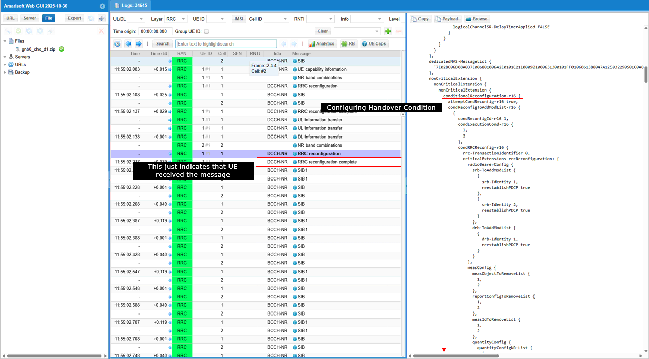
The configuration includes parameters such as physCellId = 501 and absoluteFrequencySSB = 438010 (ARFCN), indicating that the UE is expected to move to the target cell operating on this frequency when the condition is met.
UE sends RRC Reconfiguration Complete to the source gNB, confirming successful reception of the conditional handover configuration without actually executing the handover yet. This message indicates that the UE has stored the conditional handover command and is ready to trigger the move once the predefined condition (e.g., Event A3 threshold) is met. At this stage, the UE remains connected to the source cell and continues normal operation while monitoring measurements for the trigger event.
UE performs RACH on the target cell once the conditional handover trigger condition is satisfied. The PRACH transmission is initiated to establish uplink synchronization with the target gNB.
After receiving the RAR (Random Access Response) and completing the contention resolution, the UE proceeds to send RRC Reconfiguration Complete to the target gNB. This confirms successful execution of the conditional handover and activation of the target cell configuration. From this point, the UE operates under the target gNB while the data path is switched from the source to the destination.
Just for your reference, I put some important UE side log to show what's happending within UE for conditional handover.
In the UEsim Log, it shows the measurement condition for D1 is met.

And then you see the Event 3 condition is met. With both conditions specified RRC Reconfiguration, UE executes handover from PCI 500 to 501.
Test 3 : NTN SA Inter Frequency Conditional Handover - with Event T1
In this test, I will show on a scenario to trigger an handover between two NTN cells with the Event T1.
Configuration
I used the gnb-sa-ntn-multi-cell_t1.cfg which is copied and modified from gnb-sa.cfg

I also used mme-ims.cfg as it is.
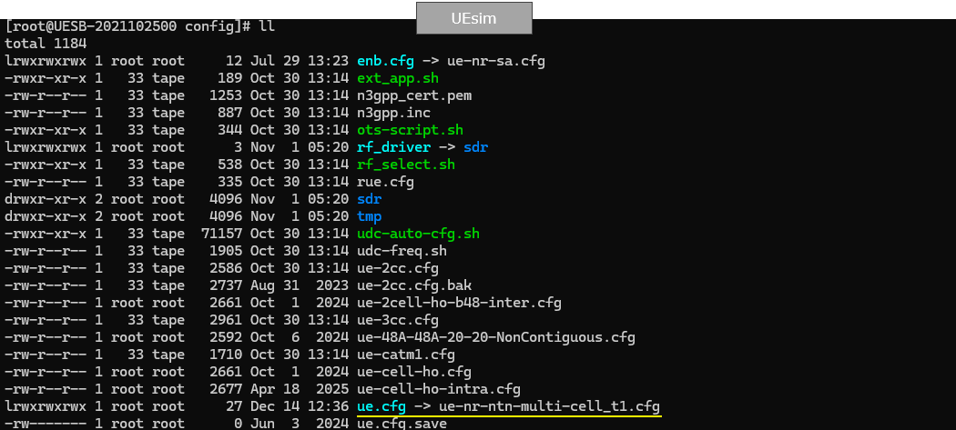
I used the ue-nr-ntn-multi-cell_t1.cfg which is copied and modified from ue-nr-sa.cfg
Configure gnb-sa-ntn-multi-cell_t1.cfg as below.
This configuration sets NTN_MODE=2 to run a LEO NTN scenario, with NR_BANDWIDTH=5 reflecting the reduced bandwidth used in NTN bands. It uses a simple SISO setup (N_ANTENNA_DL=1, N_ANTENNA_UL=1), enables satellite channel emulation via CHANNEL_SIM=1, and activates conditional handover with CHO=1.

This configuration selects different timing and reliability parameters based on the NTN orbit type. For LEO (NTN_MODE=2), shorter CSI/SRS periods (CSI_SRS_PERIOD=40) are used to track fast channel variation caused by satellite motion. The T3xx timer is also shorter (T3XX_TIMER=1000) to support quicker mobility and recovery actions. A larger HARQ capability (MAX_HARQ=5) is feasible in LEO due to its shorter RTT compared to GEO and MEO.
Make it sure that you have enough number of sdr cards for this test in rf_driver. In this test, I am using only 2 cell with SISO, so dev0, dev1 would be good enough.
This configuration enables the channel simulator and applies an AWGN-only downlink channel to both NTN cells. Each cell uses the same noise setting (noise_level = -50), so the handover test focuses on NTN mobility and control behavior rather than channel fading or beam dynamics. This helps isolate handover logic under simplified satellite channel conditions.
This configuration defines an NR NTN serving cell operating in band 256 with 15 kHz SCS and a shortened SSB periodicity (ssb_period = 5) to improve UE timing tracking in LEO. NTN-specific parameters include the initial satellite elevation offset (default_elevation_offset = 55) and a reference Earth location used by the quasi-Earth-fixed NTN model. A neighbour cell is also defined and marked as a conditional handover target, allowing it to be prepared in advance as the satellite coverage moves
This part configures NTN mobility measurements and handover triggers.For NTN-specific behavior, EVENT_D1 enables a location-based handover trigger, using distance thresholds (distance_threshold_from_ref1=1000, distance_threshold_from_ref2=800) with additional hysteresis=50. When CHO is enabled, the neighbour is prepared as a conditional handover target, and in this test the CHO execution is also driven by the same Event D1 distance trigger (time_to_trigger=0 in the CHO block), which fits NTN where handover timing can be predicted from satellite/beam geometry rather than only radio level changes.
I added neighbour cell list(ncell_list) to the configuration of the second cell and add the first cell(n_id_cell:1) as the neighbour cell and set conditional_handover_target : true to enable conditional handover for the target cell.
This configuration defines the second NTN cell, mapped to rf_port=1, operating in band 256 with 15 kHz SCS and a short SSB periodicity (ssb_period=5) suitable for LEO tracking. The NTN parameters set a different initial satellite elevation offset (default_elevation_offset=-60) and a separate reference Earth location, representing a distinct satellite/beam geometry. This cell lists the first cell as its neighbour and is marked as a conditional handover target, enabling bidirectional NTN handover testing.
This configuration sets the default NR cell parameters, using NR_BANDWIDTH and the configured DL/UL antenna counts for the NTN cell. It schedules regular system information delivery, including SIB2 and SIB19, with si_periodicity=16 and a si_window_length=40. In the NTN context, SIB19 is explicitly included to provide the UE with NTN-specific information such as ephemeris data and timing advance�related parameters, which are essential for satellite-based mobility and handover.
This MAC configuration adapts HARQ limits and uplink control timers according to the NTN orbit type. In the LEO case, shorter values are used for parameters such as retx_bsr_timer, sr_prohibit_timer, prohibit_phr_timer, and time_alignment_tx_timer, reflecting the shorter RTT and propagation delay compared to GEO and MEO. Higher sr_trans_max is also allowed, enabling more responsive uplink scheduling during fast LEO NTN mobility and handover scenarios.
This configuration sets RRC timers and SRB retransmission behavior according to the selected NTN mode via predefined macros. Timers such as t300, t301, t319, and t_PollRetransmit are automatically scaled to match the orbit-dependent RTT characteristics. In the LEO NTN case, these values are shorter, enabling faster RRC recovery and signaling exchange during frequent cell and beam transitions.
This NTN configuration selects LEO operation, using default_ephemeris="leo" and a short ul_sync_validity=5 to handle fast satellite movement. The parameter dynamic_k_offset is enabled, allowing UE-specific k_offset adjustment based on UE Timing Advance reports. This supports accurate uplink timing and more stable LEO NTN mobility and handover under rapidly changing satellite geometry. The ground_position parameter defines the geographical position of the eNB, which is used in transparent NTN mode to automatically compute NTA-Common, NTA-CommonDrift, and NTA-CommonDriftVariation, supporting accurate uplink timing and stable handover.
This configuration enables NTN channel simulation using type="auto_feeder_service_link", allowing the callbox to automatically model feeder and service link delays. The ue_position (latitude/longitude) defines the Earth-fixed UE location, which must match the UE simulator configuration to correctly compute propagation delay, Doppler shift, and link geometry. With ue_doppler_shift and ue_dl_attenuation enabled, the setup reflects LEO-specific Doppler and path loss, supporting realistic NTN mobility and handover behavior.
Now let's look into UEsim(DUT) configuration. (
In ue-nr-ntn-multi-cell_t1.cfg ,N_ANTENNA_DL is set to 1 for SISO and channel bandwidth of the cell (CELL_BANDWIDTH) is set to 5 Mhz.
![]()
This UEsim configuration defines an NR cell group for an NTN scenario, with ground_position specifying the UE�s Earth-fixed location, which must match the callbox configuration to ensure consistent NTN geometry. Two NTN cells are configured on different rf_ports, both operating in band 256 with 15 kHz SCS. The parameter apply_ta_commands enables the UE to apply Timing Advance commands received from the network in multiple-UE mode. In an NR NTN scenario, this is important to correctly track uplink timing variations caused by satellite movement
Since Conditional Handover is the refature of release 16 and onwords, you need to set as_release same as (or higher than) 16. With as_release=18 the latest NTN and CHO features and behavior are enabled
Perform the test
Start LTE service and check basic cell configuration. Any cell configuration is OK as long as they are all NR cell. (
This output confirms that two NR NTN cells are active under the same gNB, both operating in band n256 with 5 MHz bandwidth and 15 kHz SCS, which is typical for NTN deployments. Each cell is mapped to a different ARFCN and PCI (cell 0x001 and 0x002), allowing them to act as distinct NTN beams/cells for handover testing
This output of 'cell ntn' shows NTN-specific runtime status for two LEO NR cells. For each cell, the system reports the satellite geometry (azimuth AZ, elevation EL), slant range RNG, and round-trip time RTT, confirming different beam/satellite positions relative to the UE. The presence of non-zero Doppler (DPLR) on DL and UL highlights typical LEO Doppler behavior, which is a key driver for NTN handover between moving beams/cells.
Adjust cell power. I used cell_gain command here instead of tx_gain because tx_gain changes broadcasting reference cell power in SIB message and UE may behave unexpectedly due to the SIB changes.
You should see the change of cell in 't' output if Handover performs properly.
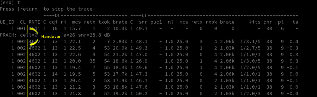
This t trace output shows a successful NTN cell handover. In the upper part of the trace, the UE is scheduled on cell 01, and a PRACH on cell 02 appears (PRACH: cell=02), indicating handover execution. Immediately after that point, the CL field changes from 001 to 002, confirming that the UE has moved to the target NTN cell/beam.
Log Analysis
The first NTN log lines shows the initial NTN context establishment for two LEO satellites (or beams). The first NTN PHY log entry per cell reports ta_common, ul_freq_shift, dl_freq_shift, along with elevation and azimuth, which together describe the initial satellite geometry and Doppler state seen by the UE.
Then check out SIB19 transmission, which is a key NTN-specific step. The UE receives Timing Advance information (ta-Common, ta-CommonDrift, ta-CommonDriftVariation) used to compensate for satellite motion�induced delay changes in transparent (bent-pipe) NTN mode. It also includes satellite orbital parameters (ephemeris), giving the UE the satellite�s position and motion needed for Doppler and timing prediction.
In addition, the reference point location (Earth-fixed coordinates) is provided, which the UE uses together with ephemeris to derive the NTN geometry. From an NTN handover perspective, correct SIB19 reception confirms that the UE has all required geometry, timing, and drift information to perform location-aware and predictive handover between moving LEO cells.
gNB sends UE Capability Enquiry to request the UE�s supported NR capabilities for the test bands. The enquiry specifically asks for band n256, with rrc-SegAllowed-r16 enabled to permit segmented capability responses. This allows the gNB to efficiently gather only the relevant NR capability information from the UE before proceeding to RRC Reconfiguration
UE sends UE Capability Information message. In this message, the UE reports support for Conditional Handover through the IEs condHandoverTriggerEvents-r16 and condHandover-r17-supported, indicating support for both event-based and enhanced CHO mechanisms. This confirms that the UE can handle predictive NTN handover, which is essential for LEO beam-to-beam or satellite-to-satellite handover driven by satellite geometry rather than only radio-level measurements.
In this same message, the UE explicitly reports NTN-specific Conditional Handover support. In particular, the IE ntn-CHO-OnlyLocationTimeTrigger-r18-supported confirms support for pure location/time�based Conditional Handover, where handover execution can rely on predicted satellite movement rather than radio measurements alone. Together, these IEs confirm that the UE can perform predictive CHO in LEO NTN, which is essential for beam-to-beam or satellite-to-satellite handover under fast-moving satellite geometry.
gNB sends RRC Reconfiguration . In this message, two measurement objects are configured, one for cell 1 and one for cell 2, each defined as a NR SSB-based measurement object. For each cell, the SSB frequency (ssbFrequency), SSB subcarrier spacing (ssbSubcarrierSpacing), SSB periodicity, and reference signal configuration are provided.
From an NTN perspective, this explicitly prepares the UE to measure SSBs from multiple NTN cells/beams in parallel, which is required for beam-to-beam or satellite-to-satellite handover. These measurement objects are the basis for triggering A3 / Event D1 / conditional handover decisions as the satellite geometry evolves.
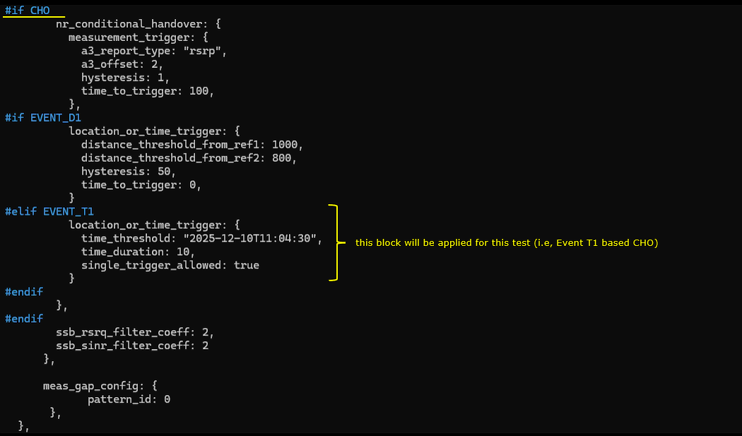
The highlighted part shown below indicates the Event T1�based measurement reporting configuration included in RRC Reconfiguration.
The first block is reportConfigToAddModList with reportType = condEventD1-r17 / condEventT1-r17, where the IE condEventT1-r17 is used. This configures a time-based trigger, with parameters such as timeThreshold-r17 and duration-r17, allowing handover execution to be driven by a predicted time condition rather than instantaneous radio measurements. This is particularly relevant for NTN, where satellite motion is deterministic. The second block is the report quantity configuration, using quantityConfigNR-List with ssb-FilterConfig and csi-rs-FilterConfig, which defines how SSB and CSI-RS measurements are filtered before reporting.
From an NTN perspective, this configuration enables pure time-based conditional handover (Event T1), which aligns well with LEO satellite movement, where handover timing can be scheduled in advance based on orbital prediction rather than signal degradation.
The first block is measIdToAddModList with Event T1, where measId is associated with reportConfigId configured for T1 reporting on Cell 1, configuring NTN location-based measurement reporting for Cell 2.
In the same message is the Conditional Handover configuration to the UE. In this message, the field conditionalReconfiguration-r16 is included with attemptCondReconfig-r16 = true, indicating that the UE is instructed to store and prepare conditional handover parameters without immediately executing the handover. The message also contains condReconfigToAddModList-r16, which specifies the configuration set for later execution when the defined trigger condition is met. This marks the transition from measurement-based preparation to actual CHO configuration, enabling the UE to perform autonomous handover once the event criteria are satisfied.
The configuration includes parameters such as physCellId = 501 and absoluteFrequencySSB = 438010 (ARFCN), indicating that the UE is expected to move to the target cell operating on this frequency when the condition is met.
UE sends RRC Reconfiguration Complete to the source gNB, confirming successful reception of the conditional handover configuration without actually executing the handover yet. This message indicates that the UE has stored the conditional handover command and is ready to trigger the move once the predefined condition (e.g., Event A3 threshold) is met. At this stage, the UE remains connected to the source cell and continues normal operation while monitoring measurements for the trigger event.
UE performs RACH on the target cell once the conditional handover trigger condition is satisfied. The PRACH transmission is initiated to establish uplink synchronization with the target gNB.
After receiving the RAR (Random Access Response) and completing the contention resolution, the UE proceeds to send RRC Reconfiguration Complete to the target gNB. This confirms successful execution of the conditional handover and activation of the target cell configuration. From this point, the UE operates under the target gNB while the data path is switched from the source to the destination.
Just for your reference, I put some important UE side log to show what's happending within UE for conditional handover.
In the UEsim Log, it shows the measurement condition for T1 is met.
With the conditions specified RRC Reconfiguration, UE executes handover from PCI 500 to 501.
RRC / NAS Signaling
RrcReconfiguration
: This is the RrcReconfiguration message sent by eNB to configure Conditional Handover (
{
message c1: rrcReconfiguration: {
rrc-TransactionIdentifier 0,
criticalExtensions rrcReconfiguration: {
measConfig {
reportConfigToAddModList {
{
reportConfigId 1,
reportConfig reportConfigNR: {
reportType condTriggerConfig-r16: {
condEventId condEventA3: {
a3-Offset rsrp: 6,
hysteresis 0,
timeToTrigger ms100
},
rsType-r16 ssb
}
}
}
},
measIdToAddModList {
{
measId 1,
measObjectId 2,
reportConfigId 1
}
},
measGapConfig {
gapUE setup: {
gapOffset 16,
mgl ms6,
mgrp ms40,
mgta ms0
}
}
},
nonCriticalExtension {
nonCriticalExtension {
nonCriticalExtension {
nonCriticalExtension {
conditionalReconfiguration-r16 {
attemptCondReconfig-r16 true,
condReconfigToAddModList-r16 {
{
condReconfigId-r16 1,
condExecutionCond-r16 {
1
},
condRRCReconfig-r16 {
rrc-TransactionIdentifier 0,
criticalExtensions rrcReconfiguration: {
radioBearerConfig {
srb-ToAddModList {
{
srb-Identity 1,
reestablishPDCP true
},
{
srb-Identity 2,
reestablishPDCP true
}
},
drb-ToAddModList {
{
drb-Identity 1,
reestablishPDCP true
}
}
},
measConfig {
measObjectToRemoveList {
1,
2
},
measObjectToAddModList {
{
measObjectId 1,
measObject measObjectNR: {
ssbFrequency 367450,
ssbSubcarrierSpacing kHz15,
smtc1 {
periodicityAndOffset sf20: 0,
duration sf1
},
referenceSignalConfig {
ssb-ConfigMobility {
deriveSSB-IndexFromCell FALSE
}
},
quantityConfigIndex 1,
offsetMO {
},
freqBandIndicatorNR 3
}
},
{
measObjectId 2,
measObject measObjectNR: {
ssbFrequency 524890,
ssbSubcarrierSpacing kHz15,
smtc1 {
periodicityAndOffset sf20: 0,
duration sf1
},
referenceSignalConfig {
ssb-ConfigMobility {
deriveSSB-IndexFromCell FALSE
}
},
quantityConfigIndex 1,
offsetMO {
},
freqBandIndicatorNR 7
}
}
},
reportConfigToRemoveList {
1
},
reportConfigToAddModList {
{
reportConfigId 1,
reportConfig reportConfigNR: {
reportType eventTriggered: {
eventId eventA2: {
a2-Threshold rsrp: 96,
reportOnLeave FALSE,
hysteresis 0,
timeToTrigger ms256
},
rsType ssb,
reportInterval ms120,
reportAmount r1,
reportQuantityCell {
rsrp TRUE,
rsrq TRUE,
sinr TRUE
},
maxReportCells 1,
includeBeamMeasurements FALSE
}
}
}
},
measIdToRemoveList {
1
},
measIdToAddModList {
{
measId 1,
measObjectId 1,
reportConfigId 1
}
},
quantityConfig {
quantityConfigNR-List {
{
quantityConfigCell {
ssb-FilterConfig {
},
csi-RS-FilterConfig {
}
}
}
}
},
measGapConfig {
gapUE release: NULL
}
},
nonCriticalExtension {
masterCellGroup {
cellGroupId 0,
rlc-BearerToAddModList {
{
logicalChannelIdentity 4,
reestablishRLC true,
mac-LogicalChannelConfig {
ul-SpecificParameters {
priority 13,
prioritisedBitRate kBps8,
bucketSizeDuration ms100,
logicalChannelGroup 7,
schedulingRequestID 0,
logicalChannelSR-Mask FALSE,
logicalChannelSR-DelayTimerApplied FALSE
}
}
},
{
logicalChannelIdentity 1,
reestablishRLC true,
mac-LogicalChannelConfig {
ul-SpecificParameters {
priority 1,
prioritisedBitRate infinity,
bucketSizeDuration ms5,
logicalChannelGroup 0,
schedulingRequestID 0,
logicalChannelSR-Mask FALSE,
logicalChannelSR-DelayTimerApplied FALSE
}
}
},
{
logicalChannelIdentity 2,
reestablishRLC true,
mac-LogicalChannelConfig {
ul-SpecificParameters {
priority 3,
prioritisedBitRate infinity,
bucketSizeDuration ms5,
logicalChannelGroup 0,
schedulingRequestID 0,
logicalChannelSR-Mask FALSE,
logicalChannelSR-DelayTimerApplied FALSE
}
}
}
},
mac-CellGroupConfig {
schedulingRequestConfig {
schedulingRequestToAddModList {
{
schedulingRequestId 0,
sr-TransMax n64
}
},
schedulingRequestToReleaseList {
0
}
},
bsr-Config {
periodicBSR-Timer sf20,
retxBSR-Timer sf320
},
tag-Config {
tag-ToReleaseList {
0
},
tag-ToAddModList {
{
tag-Id 0,
timeAlignmentTimer infinity
}
}
},
phr-Config setup: {
phr-PeriodicTimer sf500,
phr-ProhibitTimer sf200,
phr-Tx-PowerFactorChange dB3,
multiplePHR FALSE,
dummy FALSE,
phr-Type2OtherCell FALSE,
phr-ModeOtherCG real
},
skipUplinkTxDynamic FALSE
},
physicalCellGroupConfig {
pdsch-HARQ-ACK-Codebook dynamic
},
spCellConfig {
reconfigurationWithSync {
spCellConfigCommon {
physCellId 501,
downlinkConfigCommon {
frequencyInfoDL {
absoluteFrequencySSB 367450,
frequencyBandList {
3
},
absoluteFrequencyPointA 366592,
scs-SpecificCarrierList {
{
offsetToCarrier 0,
subcarrierSpacing kHz15,
carrierBandwidth 106
}
}
},
initialDownlinkBWP {
genericParameters {
locationAndBandwidth 28875,
subcarrierSpacing kHz15
},
pdcch-ConfigCommon setup: {
controlResourceSetZero 6,
searchSpaceZero 0,
commonSearchSpaceList {
{
searchSpaceId 1,
controlResourceSetId 0,
monitoringSlotPeriodicityAndOffset sl1: NULL,
monitoringSymbolsWithinSlot '10000000000000'B,
nrofCandidates {
aggregationLevel1 n0,
aggregationLevel2 n0,
aggregationLevel4 n4,
aggregationLevel8 n0,
aggregationLevel16 n0
},
searchSpaceType common: {
dci-Format0-0-AndFormat1-0 {
}
}
}
},
searchSpaceSIB1 0,
searchSpaceOtherSystemInformation 1,
pagingSearchSpace 1,
ra-SearchSpace 1
},
pdsch-ConfigCommon setup: {
pdsch-TimeDomainAllocationList {
{
mappingType typeA,
startSymbolAndLength 40
}
}
}
}
},
uplinkConfigCommon {
frequencyInfoUL {
frequencyBandList {
3
},
absoluteFrequencyPointA 347592,
scs-SpecificCarrierList {
{
offsetToCarrier 0,
subcarrierSpacing kHz15,
carrierBandwidth 106
}
}
},
initialUplinkBWP {
genericParameters {
locationAndBandwidth 28875,
subcarrierSpacing kHz15
},
rach-ConfigCommon setup: {
rach-ConfigGeneric {
prach-ConfigurationIndex 16,
msg1-FDM one,
msg1-FrequencyStart 7,
zeroCorrelationZoneConfig 15,
preambleReceivedTargetPower -110,
preambleTransMax n7,
powerRampingStep dB4,
ra-ResponseWindow sl10
},
ssb-perRACH-OccasionAndCB-PreamblesPerSSB one: n8,
ra-ContentionResolutionTimer sf64,
prach-RootSequenceIndex l839: 1,
restrictedSetConfig unrestrictedSet
},
pusch-ConfigCommon setup: {
pusch-TimeDomainAllocationList {
{
k2 4,
mappingType typeA,
startSymbolAndLength 27
}
},
p0-NominalWithGrant -84
},
pucch-ConfigCommon setup: {
pucch-ResourceCommon 11,
pucch-GroupHopping neither,
p0-nominal -96
}
},
dummy ms500
},
ssb-PositionsInBurst shortBitmap: '8'H,
ssb-periodicityServingCell ms20,
dmrs-TypeA-Position pos2,
ssbSubcarrierSpacing kHz15,
ss-PBCH-BlockPower -60
},
newUE-Identity 17922,
t304 ms1000,
smtc {
periodicityAndOffset sf20: 0,
duration sf1
}
},
spCellConfigDedicated {
initialDownlinkBWP {
pdcch-Config setup: {
controlResourceSetToAddModList {
{
controlResourceSetId 2,
frequencyDomainResources '111111111111111110000000000000000000000000000'B,
duration 1,
cce-REG-MappingType nonInterleaved: NULL,
precoderGranularity sameAsREG-bundle
}
},
controlResourceSetToReleaseList {
2
},
searchSpacesToAddModList {
{
searchSpaceId 2,
controlResourceSetId 2,
monitoringSlotPeriodicityAndOffset sl1: NULL,
monitoringSymbolsWithinSlot '10000000000000'B,
nrofCandidates {
aggregationLevel1 n0,
aggregationLevel2 n4,
aggregationLevel4 n0,
aggregationLevel8 n0,
aggregationLevel16 n0
},
searchSpaceType ue-Specific: {
dci-Formats formats0-1-And-1-1
}
}
},
searchSpacesToReleaseList {
2
}
},
pdsch-Config setup: {
dmrs-DownlinkForPDSCH-MappingTypeA setup: {
dmrs-AdditionalPosition pos1
},
tci-StatesToAddModList {
{
tci-StateId 0,
qcl-Type1 {
referenceSignal ssb: 0,
qcl-Type typeD
}
}
},
tci-StatesToReleaseList {
0
},
resourceAllocation resourceAllocationType1,
rbg-Size config1,
mcs-Table qam256,
prb-BundlingType staticBundling: {
bundleSize wideband
},
zp-CSI-RS-ResourceToAddModList {
{
zp-CSI-RS-ResourceId 0,
resourceMapping {
frequencyDomainAllocation row4: '001'B,
nrofPorts p4,
firstOFDMSymbolInTimeDomain 4,
cdm-Type fd-CDM2,
density one: NULL,
freqBand {
startingRB 0,
nrofRBs 108
}
},
periodicityAndOffset slots80: 1
}
},
zp-CSI-RS-ResourceToReleaseList {
0
},
p-ZP-CSI-RS-ResourceSet setup: {
zp-CSI-RS-ResourceSetId 0,
zp-CSI-RS-ResourceIdList {
0
}
}
}
},
firstActiveDownlinkBWP-Id 0,
uplinkConfig {
initialUplinkBWP {
pucch-Config setup: {
resourceSetToAddModList {
{
pucch-ResourceSetId 0,
resourceList {
0,
1,
2,
3,
4,
5,
6,
7
}
},
{
pucch-ResourceSetId 1,
resourceList {
8,
9,
10,
11
}
}
},
resourceSetToReleaseList {
0,
1
},
resourceToAddModList {
{
pucch-ResourceId 0,
startingPRB 105,
intraSlotFrequencyHopping enabled,
secondHopPRB 0,
format format1: {
initialCyclicShift 1,
nrofSymbols 14,
startingSymbolIndex 0,
timeDomainOCC 0
}
},
{
pucch-ResourceId 1,
startingPRB 105,
intraSlotFrequencyHopping enabled,
secondHopPRB 0,
format format1: {
initialCyclicShift 5,
nrofSymbols 14,
startingSymbolIndex 0,
timeDomainOCC 0
}
},
{
pucch-ResourceId 2,
startingPRB 105,
intraSlotFrequencyHopping enabled,
secondHopPRB 0,
format format1: {
initialCyclicShift 9,
nrofSymbols 14,
startingSymbolIndex 0,
timeDomainOCC 0
}
},
{
pucch-ResourceId 3,
startingPRB 105,
intraSlotFrequencyHopping enabled,
secondHopPRB 0,
format format1: {
initialCyclicShift 1,
nrofSymbols 14,
startingSymbolIndex 0,
timeDomainOCC 1
}
},
{
pucch-ResourceId 4,
startingPRB 105,
intraSlotFrequencyHopping enabled,
secondHopPRB 0,
format format1: {
initialCyclicShift 5,
nrofSymbols 14,
startingSymbolIndex 0,
timeDomainOCC 1
}
},
{
pucch-ResourceId 5,
startingPRB 105,
intraSlotFrequencyHopping enabled,
secondHopPRB 0,
format format1: {
initialCyclicShift 9,
nrofSymbols 14,
startingSymbolIndex 0,
timeDomainOCC 1
}
},
{
pucch-ResourceId 6,
startingPRB 105,
intraSlotFrequencyHopping enabled,
secondHopPRB 0,
format format1: {
initialCyclicShift 1,
nrofSymbols 14,
startingSymbolIndex 0,
timeDomainOCC 2
}
},
{
pucch-ResourceId 7,
startingPRB 105,
intraSlotFrequencyHopping enabled,
secondHopPRB 0,
format format1: {
initialCyclicShift 5,
nrofSymbols 14,
startingSymbolIndex 0,
timeDomainOCC 2
}
},
{
pucch-ResourceId 8,
startingPRB 1,
intraSlotFrequencyHopping enabled,
secondHopPRB 104,
format format2: {
nrofPRBs 1,
nrofSymbols 2,
startingSymbolIndex 0
}
},
{
pucch-ResourceId 9,
startingPRB 1,
intraSlotFrequencyHopping enabled,
secondHopPRB 104,
format format2: {
nrofPRBs 1,
nrofSymbols 2,
startingSymbolIndex 2
}
},
{
pucch-ResourceId 10,
startingPRB 1,
intraSlotFrequencyHopping enabled,
secondHopPRB 104,
format format2: {
nrofPRBs 1,
nrofSymbols 2,
startingSymbolIndex 4
}
},
{
pucch-ResourceId 11,
startingPRB 1,
intraSlotFrequencyHopping enabled,
secondHopPRB 104,
format format2: {
nrofPRBs 1,
nrofSymbols 2,
startingSymbolIndex 6
}
},
{
pucch-ResourceId 12,
startingPRB 105,
intraSlotFrequencyHopping enabled,
secondHopPRB 0,
format format1: {
initialCyclicShift 9,
nrofSymbols 14,
startingSymbolIndex 0,
timeDomainOCC 2
}
},
{
pucch-ResourceId 13,
startingPRB 1,
intraSlotFrequencyHopping enabled,
secondHopPRB 104,
format format2: {
nrofPRBs 1,
nrofSymbols 2,
startingSymbolIndex 8
}
}
},
resourceToReleaseList {
0,
1,
2,
3,
4,
5,
6,
7,
8,
9,
10,
11,
12,
13
},
format1 setup: {
},
format2 setup: {
maxCodeRate zeroDot25
},
schedulingRequestResourceToAddModList {
{
schedulingRequestResourceId 1,
schedulingRequestID 0,
periodicityAndOffset sl40: 0,
resource 12
}
},
schedulingRequestResourceToReleaseList {
1
},
dl-DataToUL-ACK {
4
}
},
pusch-Config setup: {
txConfig codebook,
dmrs-UplinkForPUSCH-MappingTypeA setup: {
dmrs-AdditionalPosition pos1,
transformPrecodingDisabled {
}
},
pusch-PowerControl {
msg3-Alpha alpha1,
p0-AlphaSets {
{
p0-PUSCH-AlphaSetId 0,
p0 0,
alpha alpha1
}
},
pathlossReferenceRSToAddModList {
{
pusch-PathlossReferenceRS-Id 0,
referenceSignal ssb-Index: 0
}
},
pathlossReferenceRSToReleaseList {
0
},
sri-PUSCH-MappingToAddModList {
{
sri-PUSCH-PowerControlId 0,
sri-PUSCH-PathlossReferenceRS-Id 0,
sri-P0-PUSCH-AlphaSetId 0,
sri-PUSCH-ClosedLoopIndex i0
}
},
sri-PUSCH-MappingToReleaseList {
0
}
},
resourceAllocation resourceAllocationType1,
mcs-Table qam256,
mcs-TableTransformPrecoder qam256,
codebookSubset nonCoherent,
maxRank 1,
uci-OnPUSCH setup: {
betaOffsets semiStatic: {
betaOffsetACK-Index1 9,
betaOffsetACK-Index2 9,
betaOffsetACK-Index3 9,
betaOffsetCSI-Part1-Index1 7,
betaOffsetCSI-Part1-Index2 7,
betaOffsetCSI-Part2-Index1 7,
betaOffsetCSI-Part2-Index2 7
},
scaling f1
}
},
srs-Config setup: {
srs-ResourceSetToReleaseList {
0
},
srs-ResourceSetToAddModList {
{
srs-ResourceSetId 0,
srs-ResourceIdList {
0
},
resourceType aperiodic: {
aperiodicSRS-ResourceTrigger 1,
slotOffset 7
},
usage codebook,
p0 -84,
pathlossReferenceRS ssb-Index: 0
}
},
srs-ResourceToReleaseList {
0
},
srs-ResourceToAddModList {
{
srs-ResourceId 0,
nrofSRS-Ports port1,
transmissionComb n2: {
combOffset-n2 0,
cyclicShift-n2 0
},
resourceMapping {
startPosition 0,
nrofSymbols n1,
repetitionFactor n1
},
freqDomainPosition 0,
freqDomainShift 9,
freqHopping {
c-SRS 22,
b-SRS 3,
b-hop 0
},
groupOrSequenceHopping neither,
resourceType aperiodic: {
},
sequenceId 501
}
}
}
},
firstActiveUplinkBWP-Id 0,
pusch-ServingCellConfig setup: {
}
},
pdcch-ServingCellConfig setup: {
},
pdsch-ServingCellConfig setup: {
nrofHARQ-ProcessesForPDSCH n16,
maxMIMO-Layers 2
},
csi-MeasConfig setup: {
nzp-CSI-RS-ResourceToAddModList {
{
nzp-CSI-RS-ResourceId 0,
resourceMapping {
frequencyDomainAllocation other: '000001'B,
nrofPorts p2,
firstOFDMSymbolInTimeDomain 3,
cdm-Type fd-CDM2,
density one: NULL,
freqBand {
startingRB 0,
nrofRBs 108
}
},
powerControlOffset 0,
scramblingID 501,
periodicityAndOffset slots80: 1,
qcl-InfoPeriodicCSI-RS 0
},
{
nzp-CSI-RS-ResourceId 1,
resourceMapping {
frequencyDomainAllocation row1: '1'H,
nrofPorts p1,
firstOFDMSymbolInTimeDomain 5,
cdm-Type noCDM,
density three: NULL,
freqBand {
startingRB 0,
nrofRBs 108
}
},
powerControlOffset 0,
scramblingID 501,
periodicityAndOffset slots80: 1,
qcl-InfoPeriodicCSI-RS 0
},
{
nzp-CSI-RS-ResourceId 2,
resourceMapping {
frequencyDomainAllocation row1: '1'H,
nrofPorts p1,
firstOFDMSymbolInTimeDomain 9,
cdm-Type noCDM,
density three: NULL,
freqBand {
startingRB 0,
nrofRBs 108
}
},
powerControlOffset 0,
scramblingID 501,
periodicityAndOffset slots80: 1,
qcl-InfoPeriodicCSI-RS 0
},
{
nzp-CSI-RS-ResourceId 3,
resourceMapping {
frequencyDomainAllocation row1: '1'H,
nrofPorts p1,
firstOFDMSymbolInTimeDomain 5,
cdm-Type noCDM,
density three: NULL,
freqBand {
startingRB 0,
nrofRBs 108
}
},
powerControlOffset 0,
scramblingID 501,
periodicityAndOffset slots80: 2,
qcl-InfoPeriodicCSI-RS 0
},
{
nzp-CSI-RS-ResourceId 4,
resourceMapping {
frequencyDomainAllocation row1: '1'H,
nrofPorts p1,
firstOFDMSymbolInTimeDomain 9,
cdm-Type noCDM,
density three: NULL,
freqBand {
startingRB 0,
nrofRBs 108
}
},
powerControlOffset 0,
scramblingID 501,
periodicityAndOffset slots80: 2,
qcl-InfoPeriodicCSI-RS 0
}
},
nzp-CSI-RS-ResourceToReleaseList {
0,
1,
2,
3,
4
},
nzp-CSI-RS-ResourceSetToAddModList {
{
nzp-CSI-ResourceSetId 0,
nzp-CSI-RS-Resources {
0
}
},
{
nzp-CSI-ResourceSetId 1,
nzp-CSI-RS-Resources {
1,
2,
3,
4
},
trs-Info true
}
},
nzp-CSI-RS-ResourceSetToReleaseList {
0,
1
},
csi-IM-ResourceToAddModList {
{
csi-IM-ResourceId 0,
csi-IM-ResourceElementPattern pattern1: {
subcarrierLocation-p1 s0,
symbolLocation-p1 4
},
freqBand {
startingRB 0,
nrofRBs 108
},
periodicityAndOffset slots80: 1
}
},
csi-IM-ResourceToReleaseList {
0
},
csi-IM-ResourceSetToAddModList {
{
csi-IM-ResourceSetId 0,
csi-IM-Resources {
0
}
}
},
csi-IM-ResourceSetToReleaseList {
0
},
csi-ResourceConfigToAddModList {
{
csi-ResourceConfigId 0,
csi-RS-ResourceSetList nzp-CSI-RS-SSB: {
nzp-CSI-RS-ResourceSetList {
0
}
},
bwp-Id 0,
resourceType periodic
},
{
csi-ResourceConfigId 1,
csi-RS-ResourceSetList csi-IM-ResourceSetList: {
0
},
bwp-Id 0,
resourceType periodic
},
{
csi-ResourceConfigId 2,
csi-RS-ResourceSetList nzp-CSI-RS-SSB: {
nzp-CSI-RS-ResourceSetList {
1
}
},
bwp-Id 0,
resourceType periodic
}
},
csi-ResourceConfigToReleaseList {
0,
1,
2
},
csi-ReportConfigToAddModList {
{
reportConfigId 0,
resourcesForChannelMeasurement 0,
csi-IM-ResourcesForInterference 1,
reportConfigType periodic: {
reportSlotConfig slots80: 1,
pucch-CSI-ResourceList {
{
uplinkBandwidthPartId 0,
pucch-Resource 13
}
}
},
reportQuantity cri-RI-PMI-CQI: NULL,
reportFreqConfiguration {
cqi-FormatIndicator widebandCQI,
pmi-FormatIndicator widebandPMI
},
timeRestrictionForChannelMeasurements notConfigured,
timeRestrictionForInterferenceMeasurements notConfigured,
codebookConfig {
codebookType type1: {
subType typeI-SinglePanel: {
nrOfAntennaPorts two: {
twoTX-CodebookSubsetRestriction '111111'B
},
typeI-SinglePanel-ri-Restriction '03'H
},
codebookMode 1
}
},
groupBasedBeamReporting disabled: {
},
cqi-Table table2,
subbandSize value1
}
},
csi-ReportConfigToReleaseList {
0
}
},
tag-Id 0,
servingCellMO 1
}
}
},
masterKeyUpdate {
keySetChangeIndicator FALSE,
nextHopChainingCount 0
},
nonCriticalExtension {
nonCriticalExtension {
nonCriticalExtension {
otherConfig-v1610 {
maxCC-PreferenceConfig-r16 release: NULL,
maxMIMO-LayerPreferenceConfig-r16 release: NULL,
releasePreferenceConfig-r16 release: NULL
},
needForGapsConfigNR-r16 setup: {
}
}
}
}
}
}
}
}
}
}
}
}
}
}
}
}
}