
LTE - TTI Bundling
The purpose of this tutorial is to show you how to configure and trigger TTI bundling and verify it. TTI Bundling is a kind of retransmission mechansim being used for regular LTE Uplink (not for IoT). Why retransmission ? Main purpose is to increase the reliability of PUSCH reception by eNB. This mechanism is especially helpful for the case where radio link quality is poor. Why repetition only for Uplink ? I guess it would be because of the available transmission power. In downlink, eNB use (can use) much higher power whereas UE TX power is only up to 23 dBm. So in the condition where radio link quality is very poor, there is possibility that PUSCH reception would easily fails whereas PDSCH reception is still successful. The mechanism can be illustrated as below.
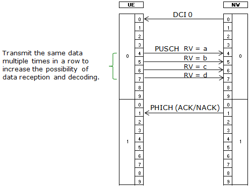
Image Source : Sharetechnote
Table of Contents
Introduction
TTI (Transmission Time Interval) bundling is a crucial feature in LTE (Long Term Evolution) designed to enhance uplink transmission reliability, especially under challenging radio conditions. In standard LTE uplink communications, the User Equipment (UE) transmits data to the evolved NodeB (eNB) over the Physical Uplink Shared Channel (PUSCH). However, when the radio link is compromised—due to factors such as distance, interference, or obstacles—there is an increased risk of uplink data loss. TTI bundling addresses this by enabling the UE to transmit the same uplink data in consecutive TTIs, effectively providing a repetition-based retransmission mechanism. This increases the probability that at least one of the repeated transmissions will be successfully received by the eNB. The mechanism is particularly relevant to the uplink because UE transmission power is significantly limited compared to the eNB's downlink capabilities; while the eNB can increase its transmission power to maintain downlink quality, the UE's maximum transmit power is typically capped at 23 dBm. As a result, the uplink is inherently more susceptible to degradation in poor radio conditions. TTI bundling plays a vital role in ensuring consistent and reliable uplink performance in LTE deployments, especially in scenarios such as cell-edge coverage or deep indoor environments. Understanding, configuring, and verifying TTI bundling is essential for network engineers and testers aiming to optimize LTE network performance and reliability.
-
Context and Background
- TTI bundling is an LTE uplink feature that enhances data reliability by transmitting repeated copies of the same uplink data across consecutive TTIs.
- It is specifically triggered in scenarios with poor radio link quality, where uplink data loss is more likely due to limited UE transmission power.
- This mechanism is implemented at the physical layer and closely interacts with the MAC and RLC layers to ensure efficient retransmission and error correction.
-
Relevance and Importance of the Tutorial
- Understanding TTI bundling is critical for optimizing LTE network performance, especially for users at cell edges or in environments with challenging radio conditions.
- Proper configuration and verification of TTI bundling can lead to measurable improvements in uplink reliability and user experience, reducing dropped calls and failed data transmissions.
- This tutorial provides practical, step-by-step guidance on configuring, triggering, and verifying TTI bundling, which is essential for network engineers, testers, and anyone involved in LTE system optimization.
-
What You Will Learn
- How TTI bundling operates within the broader LTE uplink architecture.
- The configuration steps required to enable and optimize TTI bundling for various deployment scenarios.
- Techniques to trigger and verify TTI bundling functionality using standard LTE test procedures and diagnostic tools.
- Best practices for interpreting TTI bundling performance metrics and troubleshooting common issues.
-
Prerequisite Knowledge
- Familiarity with LTE network architecture and fundamental concepts such as PUSCH, eNB, and UE.
- Basic understanding of radio link adaptation and LTE uplink/downlink procedures.
- Experience with LTE network configuration and diagnostic tools is advantageous but not strictly required.
Summary of the Tutorial
This tutorial demonstrates the procedure for configuring and testing TTI Bundling in an LTE network using Amarisoft equipment. The focus is on the impact of SNR and PHR thresholds on TTI bundling activation and provides a step-by-step methodology for setup, execution, and analysis.
-
Test Setup:
- The setup involves a callbox and a single SDR-based UE. A detailed diagram is provided to illustrate the hardware arrangement.
-
Key Configuration Parameters:
- Essential parameters include tti_bundling (with sub-parameters such as snr_threshold, phr_threshold, hysteresis, mcs_max, l_crb_max, and e_harq_pattern). These should be set according to the intended radio link conditions and test goals.
-
Test 1: TTI Bundling - SNR/PHR Threshold
-
Configuration Steps:
- Use a modified configuration file (enb-ttiBundling.cfg) based on the default eNB config.
- No special configuration is required for the core network; default MME and IMS configs are used.
- Configure tti_bundling with appropriate snr_threshold and phr_threshold values. Adjust these thresholds based on expected radio link quality.
- Optionally, extend the relevant timer to prevent premature RRC release before the test begins.
-
Test Execution Steps:
- Verify physical cell configuration to ensure it matches the intended test setup.
- Power on the UE and confirm successful network attachment.
- Initiate continuous uplink traffic (e.g., using a continuous ping) to monitor and trigger TTI bundling based on uplink SNR and PHR thresholds.
- Adjust rx_gain until the uplink SNR and PHR reach the configured tti_bundling activation criteria.
-
Log Analysis Methodology:
- Confirm UE registration completion using trace logs. Use rapid checks for key points; for detailed analysis, utilize the WebGUI tool as recommended.
- Before testing, verify that the UE supports TTI bundling by checking its capability information.
- Analyze the UL Radio Link Profile to identify periods where the tti_bundling criteria are met.
- Filter logs to focus on PUSCH transmissions. Identify TTI Bundled PUSCH by checking the tti_bundling_rep field in the log.
-
Configuration Steps:
The tutorial provides a comprehensive guide to configuring, executing, and analyzing TTI Bundling behavior under controlled SNR/PHR conditions, with emphasis on practical steps, parameter settings, and efficient troubleshooting using logging tools.
Test Setup
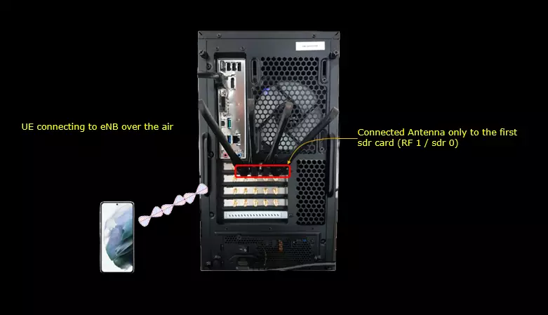
Test setup for this tutorial is as shown below.
Key Configuration Parameters
Followings are important configuration parameters for this tutorial. You may click on the items for the descriptions from Amarisoft documents.
- tti_bundling : In this link, you would get the descriptions for all the items listed below
- snr_threshold
- phr_threshold
- hysteresis
- mcs_max
- l_crb_max
- e_harq_pattern
- ul_max_harq_tx
- dl_max_harq_tx
- inactivity_timer
Test 1 : TTI Bundling - SNR / PHR Threshold
In this test, I will show you how to configure TTI bundling and how it is triggered by SNR/PHR values.
Configuration
In this tutorial, I used enb-ttiBundling.cfg which is copied and modified from enb.default.cfg.
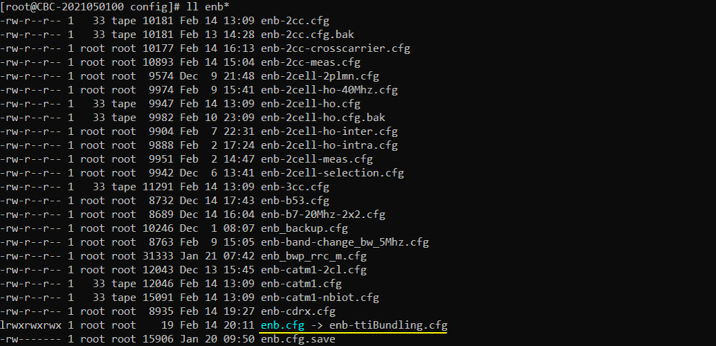
For core network, we don't need any specific configuration. So the default configuration(mme-ims.cfg and ims.default.cfg) are used as it is.

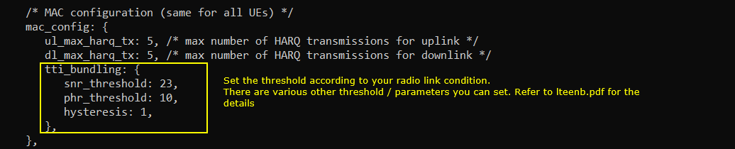
Following is the configuration in enb-ttiBundling.cfg . Configure tti_bundling parameter with snr_threshold and phr_threshold. Set these threshold according to the radio link condition in your setup. There are vaious other types of threshold and parameters you can set. Refer to the document for the details.
tti_bundling is an object inside mac_config, and mac_config is currently the same for all UEs, so there is no per UE variant of any of this. The two lines above it, ul_max_harq_tx 5 and dl_max_harq_tx 5, are the plain HARQ transmission limits and I left them as they came. The tti_bundling object itself carries snr_threshold 23, phr_threshold 10 and hysteresis 1.
snr_threshold is the UL SNR in dB, measured on PUSCH and SRS, below which the eNB configures TTI bundling, and phr_threshold is the PHR for a 1 RB allocation below which it does the same. The two conditions are OR'ed, so either one on its own is enough to switch bundling on. That is worth keeping in mind while reading the traces further down, where SNR is already in the mid teens while PHR is still in the thirties.
hysteresis is what switches it back off, and it works the other way round. Bundling is removed only when SNR is above snr_threshold plus hysteresis AND PHR is above phr_threshold plus hysteresis, both of them, so with these values the release point is 24 dB SNR and 11 dB PHR. The default is 6 dB and I dropped it to 1, which puts the on and off points close together and makes the transition easy to reach again while sweeping rx_gain. On a live cell you would want the wider default so that a UE sitting near the threshold is not switched back and forth.
mcs_max, l_crb_max and e_harq_pattern are not in this file, so they stay at their defaults, MCS capped at 10 and the bundled PUSCH allocation capped at 6 RB. The MCS cap is the one you can actually see later, in the mod field of the PUSCH log.
This configuration is not mandatory, but I extended the timer so that eNB does not release the RRC before starting test.
inactivity_timer is set to 60000, and the unit is milliseconds, so the eNB waits a full minute of network inactivity before sending the RRC connection release. A minute is enough to power on the UE, get the ping running and start moving rx_gain without the connection being torn down halfway through.

Perform the Test
Check the physical configuration of the cell and see if it is configured as intended.
There is a single LTE cell here, 0x001 on band 7 with 5 MHz bandwidth, DL ARFCN 3350 and UL ARFCN 21350. The downlink runs 2 antennas with 2 layers and 256QAM, the uplink runs 2 antennas with 1 layer and 64QAM, and the SSB columns are empty because this is LTE and there is no SSB to report. The header line gives PLMN 00101 and eNB_ID 0x1a2d0.
Band 7 being FDD is the one detail here that touches the tti_bundling configuration. e_harq_pattern is an FDD only parameter, so it would be available in this setup if you wanted to try it, whereas on a TDD band it is not an option at all.

Power on UE and confirm that UE is attached.
t brings up the running trace and it stays there until you press return. One UE shows up, UE_ID 1 on cell 001 with RNTI 0040, at cqi 15 and DL mcs 26.0. The uplink columns are the ones this test lives on. snr sits between 15.7 and 16.5, puc1 between 20.8 and 25.4, and phr reads 34.
Against snr_threshold 23 and phr_threshold 10 that already looks like a trigger, and it is not. snr_threshold is measured on PUSCH and SRS, and at this point there is barely any PUSCH to measure, with the UL brate showing only 1.2k. That is what the ping in the next step is for.

Do continuous ping to get continuous UL traffic to check UL radio link threshold for TTI Bundling.
The ping runs from the mme host to 192.168.3.2, which is the address the UE picked up, with the default 56 byte payload. Round trip times come back between 19.9 and 65.8 ms.
The latency is not the point and neither is the payload size. What this gives you is a PUSCH every second for the eNB to measure SNR on, which is what snr_threshold is checked against. If you want the transition to be sharper, a shorter interval with ping -i gives the eNB more PUSCH to work with over the same span of time.

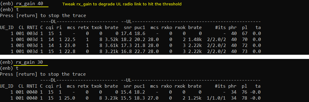
Tweak rx_gain to until UL SNR and PHR hits the triggering criteria of the tti bundling.
Two settings are stacked here so they can be compared directly. At rx_gain 40 the uplink reads snr between 16.8 and 18.2, puc1 between 18.6 and 22.7, phr 40 and pl from 67 up to 73. At rx_gain 30 the same columns read snr around 15.4 to 15.5, puc1 around 18.2, phr 34 and pl 76 to 78. Ten dB off the receiver gain moves phr down by 6 and pl up by roughly 7.
The retx and #its columns move with it. At rx_gain 40 two of the rows show retx 1 and #its reads 2/2.0/2, while at rx_gain 30 retx stays at 0 and #its reads 1/1.0/1.
What this step cannot tell you is whether bundling actually engaged, because the t output has no field for it. All you are doing here is walking the link into the region where the thresholds are met and leaving it there long enough to be visible. The confirmation comes from the PUSCH rows in the log analysis below.
Log Analysis
In this section, you will see how to confirm if UE registration is complete from trace log. You can use the same method to find any issues (e.g, registration failure) for troubleshooting. When UE registration fails, you may use this tutorial to figure out the point of the failure and troubleshoot
NOTE : This section is just to check quickly some important points in the log, but it may be a little bit tricky to do the detailed log analysis (especially for lower layer log analysis). In that case, I strongly recommend you to use WebGUI for the log analysis. You may refer to WebGUI Tutorial
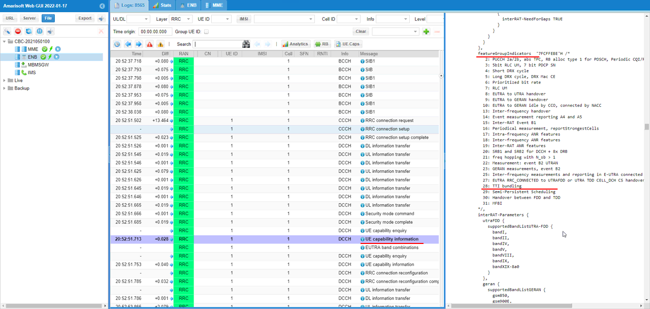
Before you try the test, I strongly suggest you to check on UE capability for your UE and confirm that it support the TTI Bundling that you want to try. You should see 'TTI bundling' is specified in featureGroupIndicators.
In this log featureGroupIndicators reads '7FCFFEBE'H with the decoded bit list printed underneath, and bit 28 is the one that says TTI bundling. It arrives inside UE capability information on DCCH, which the eNB pulls out of the UE with the UE capability enquiry a couple of rows above it. Setting the Layer filter to RRC is what gets you to that pair without scrolling through the PHY rows.
If bit 28 is not there, stop before you configure anything. The UE has not declared support and nothing you do to snr_threshold or rx_gain will produce a bundled PUSCH.
There is a second capability worth a thought while you are in this message. l_crb_max defaults to 6 RB, but a UE that does not support noResourceRestrictionForTTIBundling-r12 has its bundled PUSCH allocation capped at 3 RB regardless of what you put in the configuration file.
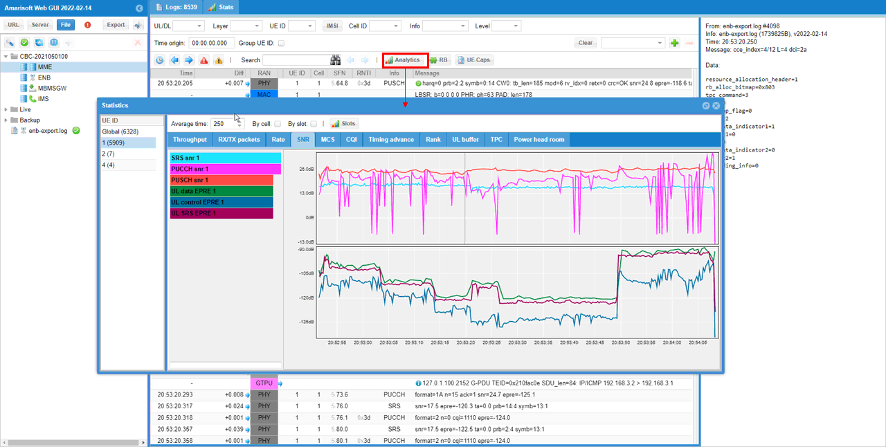
Check overall UL Radio Link Profile and check if there is any span where it hits the tti bundling criteria you specified.
This comes from the Analytics button in the toolbar, on the SNR tab. Average time is set to 250, which is what keeps the curves readable instead of a wall of individual samples, and the UE ID list on the left has 1 selected out of the four that appear in this log.
The upper chart carries SRS snr 1, PUCCH snr 1 and PUSCH snr 1 on a scale running from 26.0 dB down through 13.0 dB, 0.0 dB and -13.0 dB. SRS holds near the top for the whole log. PUSCH is the one that drops, in narrow spikes that reach below 0 dB, and each of those is a single reception rather than a change in the link.
The lower chart is EPRE, from -90 dBm down to -135 dBm, with UL data EPRE 1, UL control EPRE 1 and UL SRS EPRE 1 on it. There is a step down at roughly 20:53:05 and a step back up at roughly 20:53:50, and that flat lower section is the span where rx_gain was reduced. Note those two timestamps down. When you get to the PUSCH rows below, the point where tti_bundling_rep starts appearing falls inside this window, and lining the two up is the check that the trigger came from what you did and not from something else.
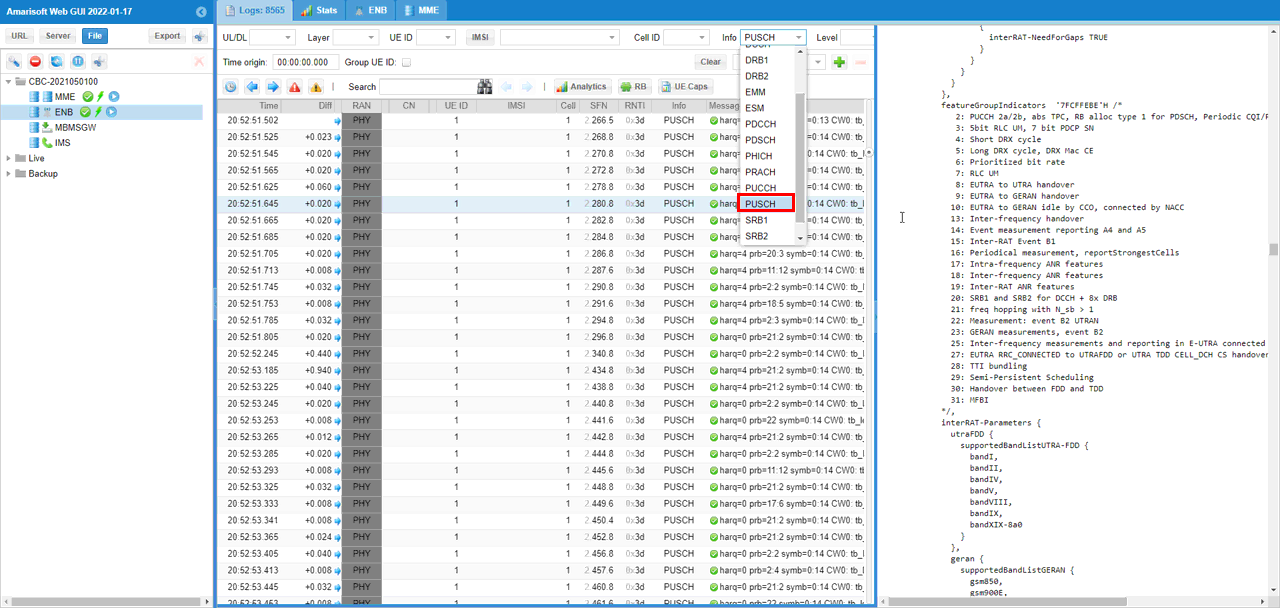
Filter PUSCH only for easy analysis.
The filter is the Info dropdown, not the Layer one. It lists the message types the log contains, DRB1, DRB2, EMM, ESM, PDCCH, PDSCH, PHICH, PRACH, PUCCH, PUSCH, SRB1, SRB2 and the rest, and PUSCH is the entry to pick.
With that applied every remaining row is a PHY PUSCH entry and the Message column reads harq, prb, symb and then the CW0 fields. Filtering on Info rather than on Layer keeps the timestamps unbroken, which is what you want when the thing you are hunting for is the exact row where the behaviour changes.
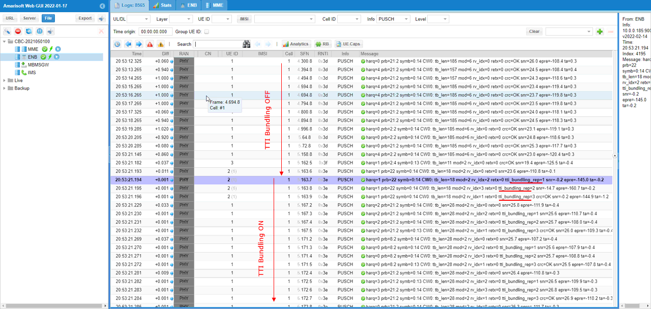
In PUSCH log print, you can easily check whether they are regular PUSCH or TTI Bundled PUSCH by checking tti_bundling_rep field in the log print.
The rows in the upper half have no tti_bundling_rep on them at all and read like harq=0 prb=21:2 symb=0:14 CW0: tb_len=185 mod=6 rv_idx=0 retx=0 crc=OK snr=26.0 epre=-108.4 ta=0.3. Below the transition, at around 20:53:21.194, the field appears and the rows arrive in groups of four, one millisecond apart. The first of each group has no tti_bundling_rep, then come tti_bundling_rep=1, 2 and 3, with rv_idx cycling through 0, 2, 3 and 0 and crc=OK landing on the last of the four. That group of four is one bundle.
Two other fields change across the same line. mod drops from 6 to 2 and tb_len drops from 185 to 28, on the same prb=21:2 allocation, so it is not the allocation that shrank. That is mcs_max doing its job, capping the PUSCH MCS at 10 while bundling is active, and it is the one default from the tti_bundling block you can read straight off the log.
The RNTI column changes at the same point too, from 0x3d above to 0x3e below. Configuring and deconfiguring TTI bundling is done through an intra-cell handover, so the UE picks up a new C-RNTI every time it is switched. That is worth knowing for two reasons. It means the switch costs a handover rather than being free, and it gives you a second way to spot the transition when the Message column is too wide to show tti_bundling_rep without scrolling.
Do not read too much into the per row snr on either side of the line. It swings from 23.6 down to -0.2 and back into the mid twenties within a few milliseconds, because each row is one reception. The Analytics chart above is where you read the trend; these rows are where you read the individual outcome.
RRC / NAS Signaling
RrcConnectionReconfiguration
: This is the RrcConnectionReconfigurationmessage sent by eNB to enable TTI bundling. (
{
message c1: rrcConnectionReconfiguration: {
rrc-TransactionIdentifier 0,
criticalExtensions c1: rrcConnectionReconfiguration-r8: {
...
radioResourceConfigDedicated {
mac-MainConfig explicitValue: {
ul-SCH-Config {
maxHARQ-Tx n5,
periodicBSR-Timer sf20,
retxBSR-Timer sf320,
ttiBundling TRUE
},
drx-Config release: NULL,
timeAlignmentTimerDedicated infinity,
phr-Config setup: {
...
}
},
physicalConfigDedicated {
...
}
},