
LTE SG SMS
This tutorial shows how to test SMS over SG with Amari Callbox. In this tutorial, it is assumed that you are already familiar with basic operations of the Callbox software and I would point out the only important parts of the operation specific to this test.
We have been using SMS in every radio technology (i.e, 3G, 4G, 5G) and user interface on commercial mobile phone would look same whatever radio technology is used, but the detailed protocol behind the SMS differs with the radio access technology being used.
- 3G : SMS go through NAS messages carried by CS(Circuit Switch) channel
- LTE : Two different ways are used
- SG SMS : SMS go through NAS message // this is the topic for this tutorial.
- SM over IMS : SMS go through IMS // check out this tutorial for this
- 5G : SMS goes through IMS
One common thing regardless of the method listed above is that the way SMS message is being encoded and protocols at the level of session menagement (i.e, CP-DATA, CP-ACK etc). Putting it other way, same format of SMS and session layer protocol is encapsulated in different way (i.e, NAS message or IMS) depending on different radio technology.
Table of Contents
Introduction
Short Message Service (SMS) remains a fundamental communication feature across all generations of mobile networks, including 3G, LTE, and 5G. Despite its consistent user interface across devices, the underlying mechanisms for SMS delivery differ significantly depending on the radio access technology and core network architecture in use. In LTE networks, SMS delivery can be achieved through two primary methods: via the SGs interface (commonly referred to as SMS over SG), where SMS messages are transported over NAS (Non-Access Stratum) signaling between the Mobile Switching Center (MSC) and the Mobility Management Entity (MME), or via IMS (IP Multimedia Subsystem), where SMS is delivered as an application-level message over an IP connection. The SGs interface enables LTE networks to support legacy SMS services in scenarios where IMS is not available or not preferred, ensuring backward compatibility and seamless user experience. Amari Callbox, a versatile radio testing platform, facilitates comprehensive testing of SMS over SG by emulating network elements and providing controlled environments to validate device behavior, signaling procedures, and protocol compliance. Understanding the architectural principles, protocol encapsulation techniques, and configuration requirements is crucial for engineers and testers aiming to validate SMS functionality over the SGs interface, as well as for troubleshooting interoperability across heterogeneous network deployments. This tutorial focuses on the practical aspects of testing SMS over SG with Amari Callbox, highlighting the specific configuration steps and operational nuances distinct to this scenario, while assuming familiarity with the basic operation of the Callbox software.
-
Context and Background
- SMS delivery mechanisms vary based on the radio access technology (3G, LTE, 5G), with core network signaling adapting accordingly.
- In LTE, SMS can be delivered via:
- SMS over SG (SGs interface): Uses NAS signaling between the MME and MSC to support SMS without IMS.
- SM over IMS: Leverages the IP Multimedia Subsystem for SMS delivery over IP networks.
- The SGs interface is essential for maintaining SMS service continuity as networks transition from circuit-switched to packet-switched domains.
- Amari Callbox provides a controlled testbed for simulating and validating SMS over SG procedures on user equipment (UE).
-
Relevance and Importance
- Ensures compatibility and compliance of mobile devices with legacy SMS delivery in LTE environments where IMS may not be available.
- Supports operators and device manufacturers in verifying correct protocol implementation, session management (e.g., CP-DATA, CP-ACK), and message encapsulation.
- Facilitates troubleshooting and optimization of SMS services across multi-generation network deployments.
- Enhances quality assurance processes by enabling reproducible test scenarios using Amari Callbox.
-
Learner Outcomes
- Develop an in-depth understanding of SMS over SG architecture and signaling flows in LTE networks.
- Gain hands-on experience configuring Amari Callbox for SMS over SG test scenarios.
- Acquire the ability to analyze and interpret protocol exchanges specific to SMS over SG delivery.
- Learn best practices for device configuration and network parameter selection impacting SMS routing.
-
Prerequisites
- Familiarity with Amari Callbox basic operations and interface navigation.
- Understanding of LTE network architecture, especially NAS signaling and core network elements (MME, MSC).
- Basic knowledge of SMS protocol structure and session management concepts.
- Access to a device under test (UE) and Amari Callbox test environment.
Summary of the Tutorial
This tutorial demonstrates the procedures for configuring and testing both Mobile Originated (MO) and Mobile Terminated (MT) SMS over SG (NAS message) in an LTE network using Amarisoft Callbox and a test UE.
- Test Setup:
- Uses the default SIM card delivered with the system.
- Configuration can be customized via the Configuration Guide if required.
- Preconditions:
- Ensure the UE supports SMS over SG by confirming the relevant Information Elements (IE) in NAS messages during the attach procedure.
- Check the "Voice domain preference and UE's usage setting" and "Additional update type" IEs to verify SMS over SG capabilities.
- Key Configuration Parameters:
- Set force_sms_over_sg parameter to enforce SMS over SG.
- Test 1: MO SG-SMS (Mobile Originated SMS over SG)
-
Configuration Steps:
- Use the default enb.default.cfg (LTE eNB config) and mme-ims.cfg (MME config) without modification.
- Ensure ue_db-ims.cfg is referenced as the UE database in mme-ims.cfg.
- Use the Anritsu Test USIM and note the 'tel' number for SMS testing.
- On the UE, use the default APN. Remove IMS APN (if present) and optionally disable VoLTE to ensure SMS is sent over SG rather than IMS.
-
Test Procedure:
- Start LTE service and confirm basic cell configuration.
- Power on the UE and verify successful registration to the LTE cell.
- Ensure UE is not assigned an IMS PDN; otherwise, SMS may be sent over IMS.
- Send an SMS from the UE using the configured 'tel' number as the destination.
- Verify SMS delivery and receipt of delivery notice from the SMS server.
-
Log Analysis:
- Enable NAS, SIP, and IMS logs in the WebGUI for analysis.
- Filter logs to display NAS, SIP, and IMS messages for clarity.
- Observe the sequence of message transactions, noting that even though the SMS is carried by NAS, the IMS server acts as the SMS center.
- Review Uplink and Downlink NAS transport messages for SMS transactions. For actual SMS contents, refer to IMS logs as NAS logs may not show decoded SMS payloads.
-
Configuration Steps:
- Test 2: MT SG-SMS (Mobile Terminated SMS over SG)
-
Configuration Steps:
- Use the default enb.default.cfg for eNB configuration.
- Use ims.default-sg-sms.cfg (copied from ims.default.cfg), mme-ims-sg-sms.cfg (from mme-ims.cfg), and ue_db-ims-sg-sms.cfg (from ue_db-ims.cfg) for MME and IMS configuration.
- Set force_sms_over_sg : true in the configuration to ensure SG SMS is used regardless of IMS registration status.
- No need to disable IMS/VoLTE on the UE, as force_sms_over_sg enforces SG SMS mode on the callbox.
-
Test Procedure:
- Start LTE service and verify cell configuration.
- Power on the UE and confirm successful registration.
- Check registered users in IMS to ensure IMPI and binding information are present (IMS registration is optional for SG SMS).
- Send an SMS from the IMS interface and confirm receipt on the UE.
- Repeat the test using IMPI as the destination and verify successful SMS delivery to the UE.
- To confirm that SMS was transmitted over SG, inspect relevant logs.
-
Log Analysis:
- Enable NAS, SIP, and IMS logging in the WebGUI.
- Filter logs for NAS, SIP, and IMS messages.
- Analyze the logs to confirm SMS delivery and that SG SMS path was utilized.
-
Configuration Steps:
General Notes on Log Analysis:
- For both MO and MT SG-SMS tests, Amarisoft IMS server functions as the SMS center, even though the actual SMS is carried in NAS messages.
- SMS message contents can be verified in IMS logs, as NAS logs may not display the decoded SMS payload.
- Both uplink and downlink NAS transport messages should be inspected to confirm SMS transmission and delivery notifications.
Test Setup
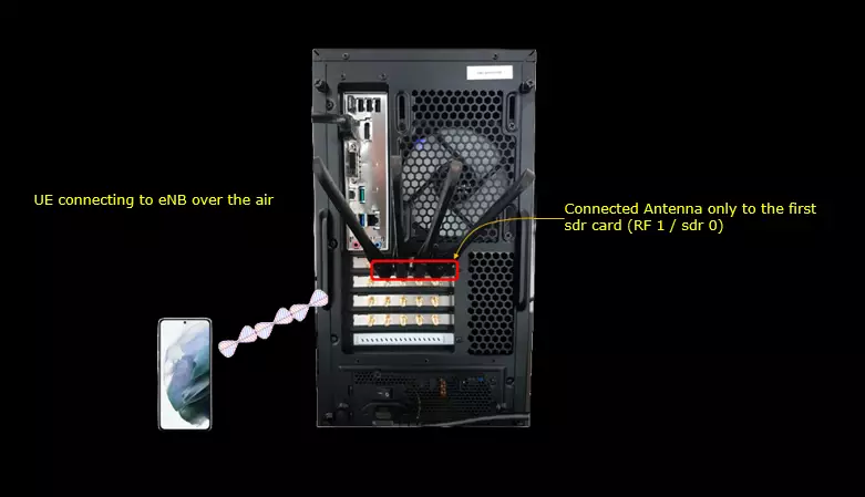
Test setup for this tutorial is as shown below.
- SIM Card used in this tutorial is the one delivered with the system as it is.
- If you want to change the configuration, The tutorial Configuration Guide would help
PreConditions
To test SMS over SG, the first thing to confirm is that the UE supports SMS over SG. This can usually be checked from the NAS messages during the attach procedure. The most important indication is found in the Voice domain preference and UE's usage setting IE. In the example shown here, the UE reports 0x07, which means IMS PS voice preferred, CS Voice as secondary, and Data centric. This indicates that the UE is not purely IMS-only from the LTE point of view and it can still support CS-related fallback behavior, which is one of the required conditions for SG SMS operation.
Another point to check is whether the UE requests combined EPS and non-EPS registration. SG SMS depends on the UE being registered not only to EPS but also to the non-EPS domain through the SGs interface. If the UE performs only normal EPS attach without combined registration, the network may not be able to deliver SMS through SGs even if the radio attach itself is successful.
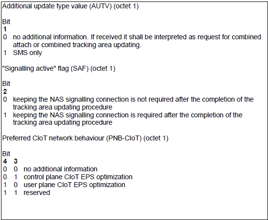
If the UE only supports EPS service and does not support non-EPS service in combined mode, it may still indicate SMS support using the Additional update type IE. In this IE, the lower bit field is used as the Additional update type value, AUTV. When AUTV is set to 1, it means SMS only. This tells the network that the UE is requesting SMS support without requesting full combined EPS and non-EPS service.
The Additional update type IE also includes the SAF bit and the PNB-CIoT field. SAF indicates whether the NAS signalling connection should be kept after the tracking area updating procedure, and PNB-CIoT indicates the preferred CIoT network behavior. These fields are not the main focus of this SG SMS test, but they may appear together in the same IE depending on UE capability and NAS procedure. For this tutorial, the key point is to check whether the UE indicates either combined EPS/non-EPS registration support or SMS-only support through the Additional update type IE.
First thing you may check is to check if the following IE is configured.
|
ESM message container: Protocol discriminator = 0x2 (EPS Session Management) EPS bearer identity = 0 Procedure transaction identity = 94 Message type = 0xd0 (PDN connectivity request) Request type = 1 (initial request) ... Last visited registered TAI: ... ... |
If the UE only supports EPS service and not non EPS service (combined mode) it can also indicate the SMS support with the Additional update type IE lower bit
< 24.301-Figure 9.9.3.0B.1: Additional update type information element >

< 24.301-Table 9.9.3.0B.1: Additional update type information element >
Key Configuration Parameters
Followings are important configuration parameters for this tutorial. You may click on the items for the descriptions from Amarisoft documents.
Test 1 : MO SG-SMS
This is to show how to configure and test MO (Mobile Originated) SMS over SG (NAS message).
Configuration
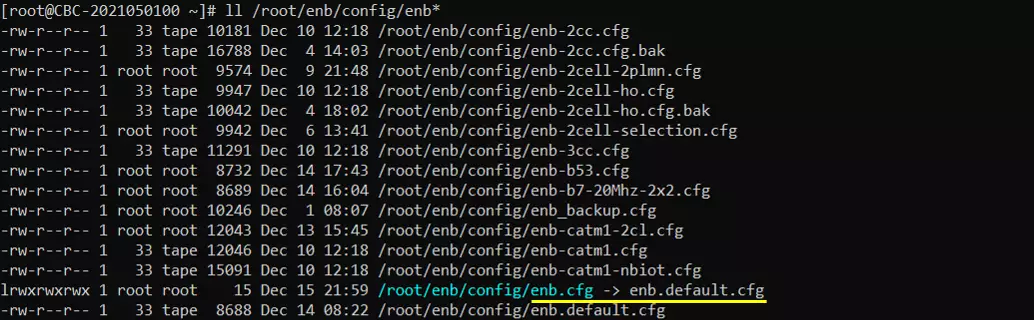
I used the enb.default.cfg (LTE default configuration) as it is without changing any contents in it.
I also used the default configuration(mme-ims.cfg) for mme as shown below.
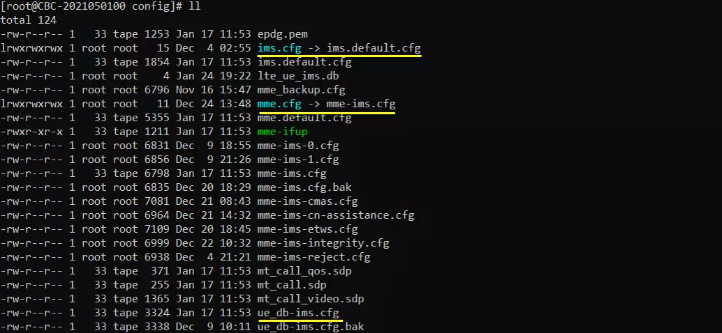
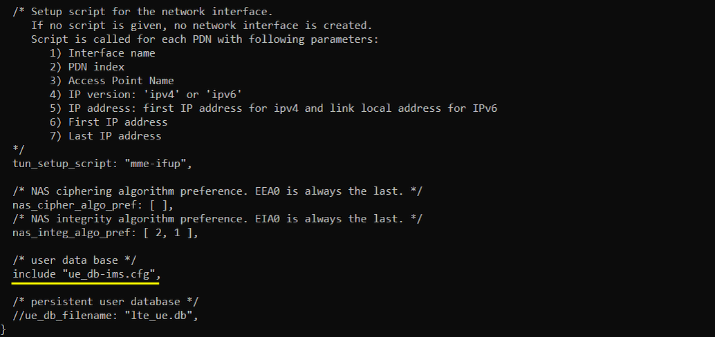
In mme-ims.cfg file, you would notice that ue_db-ims.cfg is used as ue db.
In this example, the MME configuration includes ue_db-ims.cfg as the user database, as shown by include "ue_db-ims.cfg". This means that the UE subscription information used for attach, authentication, APN, IMS, and SMS related service behavior is taken from ue_db-ims.cfg rather than from a persistent lte_ue.db file.
For this SG-SMS test, this is important because the UE must be known to the MME and the subscription profile must allow the required EPS service. If the wrong UE database file is included, or if the IMSI used by the UE is not defined in the included database, the UE may fail during attach or may attach with a profile that does not match the intended SMS test scenario.
The other parameters shown in this part are general MME settings. tun_setup_script: "mme-ifup" is used to create and configure the network interface for each PDN connection, nas_cipher_algo_pref defines the NAS ciphering algorithm preference, and nas_integ_algo_pref defines the NAS integrity algorithm preference. These parameters are not specific to SG-SMS itself, but they are part of the basic MME configuration required for normal LTE attach and NAS signalling operation.
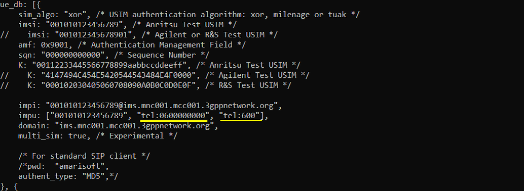
In this tutorial, I am using an Anritsu Test USIM. In ue_db-ims.cfg, check that the IMSI, authentication key, and IMS related user information match the USIM being used by the UE. In this example, imsi: "001010123456789" and K: "00112233445566778899aabbccddeeff" are configured for the Anritsu Test USIM, so the UE can be authenticated successfully during LTE attach.
Also check the impi, impu, and tel fields. impi defines the private IMS identity, and impu defines the public user identity used for IMS service. Even though this test is for SG-SMS rather than SMS over IMS, the same ue_db-ims.cfg file is used in this example, so these IMS related fields may still be present in the UE database.
The most important field for this SMS test is tel. In this example, tel: "600" is configured as the telephone number for this UE. Remember this number because it will be used when sending or receiving SMS. When you test SMS between two UEs, each UE should have its own tel number configured in the UE database, and the destination number used in the phone messaging application should match the tel value of the peer UE.
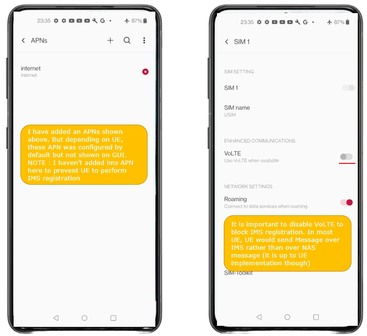
For the UE side configuration, I used the default internet APN only. It is recommended to remove the IMS APN if it was already added, because the purpose of this test is to force the UE to send SMS over SG using NAS signalling rather than sending SMS over IMS. Depending on the UE implementation, the IMS APN may be configured internally by default even if it is not shown clearly in the APN GUI, so it is better to keep only the normal data APN as much as possible for this test.
It is also recommended to disable VoLTE on the UE. In many commercial phones, enabling VoLTE triggers IMS registration, and once IMS registration is successful the phone may prefer SMS over IMS instead of SG-SMS. In that case, the SMS may still work from the user point of view, but it would not verify the SG-SMS procedure that we want to test here. By disabling VoLTE and avoiding IMS APN configuration, the UE is more likely to use NAS-based SMS over SG after LTE attach and SGs registration are completed.
Perform the test
Start the LTE service on the Callbox and check the basic cell configuration. For this SG-SMS test, there is no special radio configuration requirement. Any normal LTE cell configuration is acceptable as long as the UE can camp on the cell and complete LTE attach successfully.
In this example, cell phy shows that the configured PLMN is 00101 and the eNB ID is 0x1a2d0. The cell is LTE Band 7 with 5 MHz bandwidth, downlink ARFCN 3350, uplink ARFCN 21350, and PCI 2. This confirms that the LTE physical cell is running normally.
The cell command gives another quick summary of the LTE cell configuration. It shows TAC 0x0001, downlink ARFCN 3350, PCI 1, PRACH sequence 204, and PLMN 00101. For this test, the most important point is not the specific band, bandwidth, or PCI value, but that the LTE cell is active with the expected PLMN and TAC so that the UE can find the cell, attach to the network, and proceed to the SG-SMS procedure.

Power On UE and make it sure that UE get registerred.
Once the UE is registered, you can confirm it from the eNB screen using the ue command. In this example, the UE is shown with RAN_UE_ID 1, CN_UE_ID 100, Cell 0x001, and RNTI 0x003d. This means that the UE has successfully established the radio connection with the eNB and the eNB has also associated this UE with the core network context.
At this point, the UE is attached at the LTE level and ready for the next step of the SG-SMS test. The ue command itself does not prove that SMS over SG is already working, but it confirms the basic prerequisite that the UE is connected and registered in the LTE network. After this, you can proceed to trigger SMS from the UE and check the NAS and SGs related messages in the Callbox logs.

Make sure that the UE is not assigned with an IMS PDN. If the UE is assigned with an IMS PDN, it is likely that the UE will use SMS over IMS rather than SG-SMS when you send an SMS from the phone.
You can check this from the MME screen using the ue command. In this example, the UE with SUPI 001010123456789 is registered to EPC, REG is Y, TAC is 0x1, and only one bearer is assigned. The IP address 192.168.3.2 is shown for the UE, and there is no separate IMS PDN or IMS bearer listed. This is the expected condition for this SG-SMS test because the UE is attached for normal EPS data service, but IMS registration is not being established through an IMS PDN.
At this point, the UE is registered to LTE and has only the default data PDN. This helps force the SMS procedure to use NAS-based SG-SMS rather than IMS messaging.

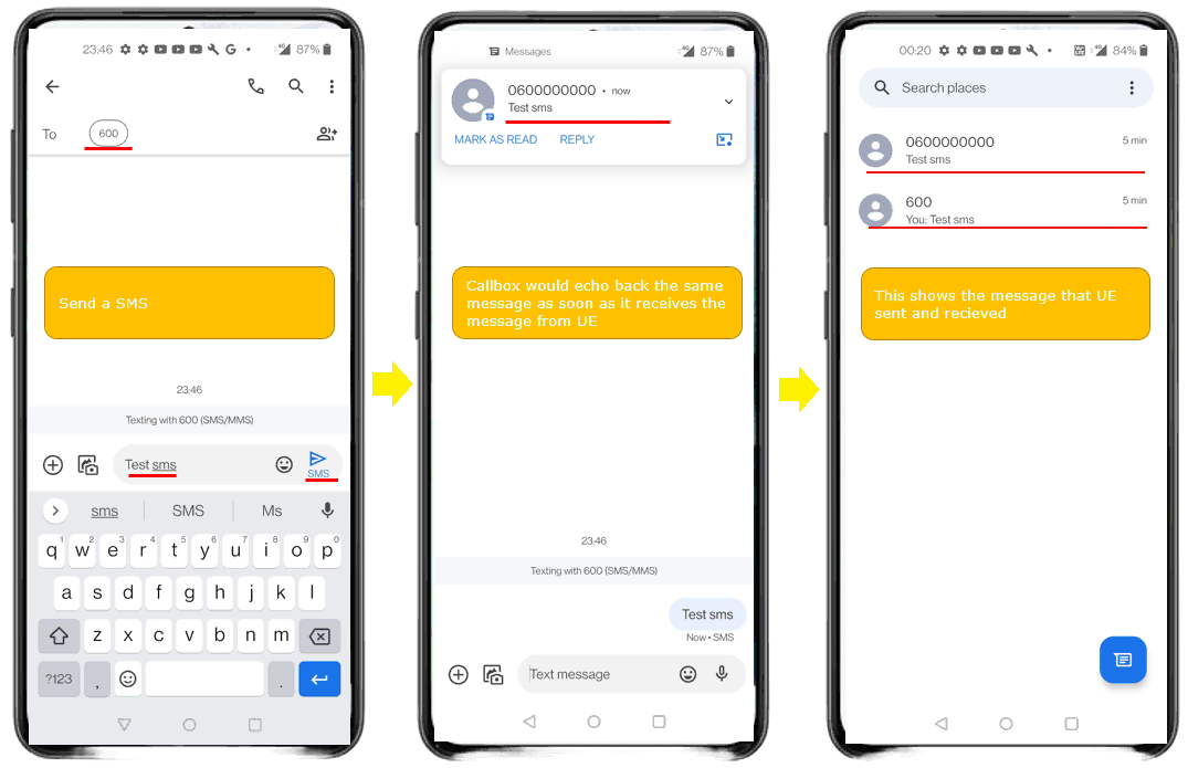
Send SMS from the UE and check the result on the phone screen. In this example, I am using the tel number configured in ue_db-ims.cfg as the destination address. Since tel: "600" was configured for this UE, the SMS destination number is entered as 600 in the phone messaging application.
After entering the destination number and message text, send the SMS from the UE. In this example, the message text is Test sms. Once the Callbox receives the MO SMS from the UE, it delivers the message to the internal SMS server and echoes the same message back to the UE. As a result, the UE shows both the sent message and the received message in the messaging application.
The received notification confirms that the SMS was successfully delivered to the SMS server and then sent back to the UE. From the phone user interface, this looks like a normal SMS exchange, but in this test the important point is that the SMS was sent without IMS registration and without IMS PDN assignment. This indicates that the message was carried through the SG-SMS path using NAS signalling rather than SMS over IMS.
Log Analysis
To analyze the SG-SMS procedure, enable at least NAS, SIP, and IMS logs in the WebGUI log viewer. For easier analysis, you can filter the log with NAS, SIP, and IMS. Even though this test is not using SMS over IMS, the IMS log is still useful in Amarisoft Callbox because the internal IMS server also acts as the SMS center for this test.
In the sample log, the UE first completes the normal LTE attach procedure. You can see Attach complete, followed by IMSI register and IMSI register ack. This indicates that the UE is registered in the Callbox system and the SMS service can associate the UE identity with the configured tel number.
When the SMS is sent from the UE, the log shows Uplink NAS transport messages. These messages carry the MO SMS payload from the UE to the network through NAS signalling. Inside this NAS transport, the SMS control protocol messages such as SMS-CP are exchanged. This confirms that the SMS is not being sent through IMS SIP MESSAGE, but through the NAS-based SG-SMS path.
In the selected log line, the message shows SMS src=0600000000 dst=600: received, and the data field shows text="Test sms". This means that the Callbox SMS server received an SMS whose destination number is 600, and the decoded SMS text is Test sms. The source number shown in the log may be generated or formatted internally by the Callbox, while the destination number corresponds to the tel number configured in the UE database.
After the SMS server receives the MO SMS, the Callbox sends the same message back to the UE. This is why the log also shows SMS src=0600000000 dst=600: sending, followed by Downlink NAS transport messages. These downlink NAS transport messages carry the MT direction SMS back to the UE. Therefore, the full log sequence confirms both directions: the UE sends the SMS to the Callbox SMS server over NAS, and the Callbox echoes the SMS back to the UE over NAS.
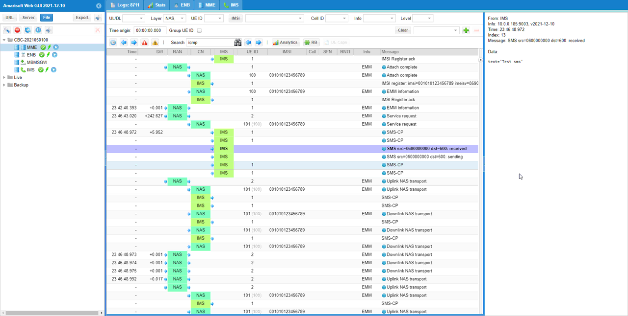
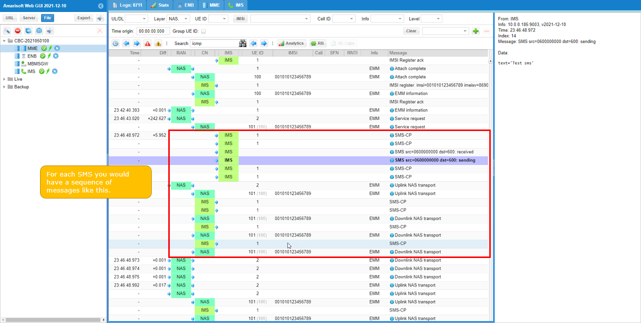
For each SMS you send from the UE, you will see a sequence of SMS transaction messages in the WebGUI log. Even though the SMS payload is carried by NAS signalling in this SG-SMS test, Amarisoft still shows some IMS log entries because the internal IMS server is used as the SMS center in the Callbox implementation.
In the highlighted part of the log, the SMS transaction starts after the UE sends the SMS from the phone application. The log shows SMS-CP messages, followed by SMS src=0600000000 dst=600: received. This means that the Callbox SMS server received the SMS whose destination number is 600. The right-side detail window shows the decoded message text as text="Test sms", which confirms that the SMS payload was successfully decoded by the Callbox.
After receiving the MO SMS, the Callbox sends the same message back to the UE. This is shown by SMS src=0600000000 dst=600: sending, followed by additional SMS-CP and Downlink NAS transport messages. The Downlink NAS transport messages carry the returned SMS back to the UE over NAS signalling.
So, for one SMS sent from the UE, you normally see both directions in the log. First, the UE sends the SMS to the Callbox SMS server through Uplink NAS transport and SMS-CP. Then, the Callbox echoes the SMS back to the UE through Downlink NAS transport and SMS-CP. This complete sequence confirms that the MO SG-SMS path is working and that the returned SMS is also delivered back to the UE through the NAS-based SMS path.
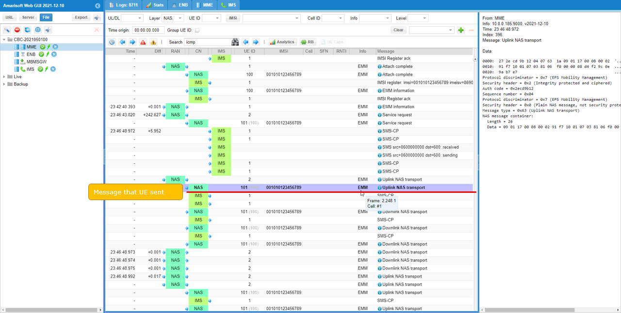
If you check the Uplink NAS transport message, you can see the NAS message that carries the SMS payload from the UE to the network. This is the key NAS message for confirming that the SMS is being transported over NAS in the uplink direction.
In the selected log, the message is Uplink NAS transport and the detailed view shows that this is an EMM message with Protocol discriminator = 0x7, EPS Mobility Management, and Message type = 0x65, Uplink NAS transport. Inside this message, the NAS message container carries the SMS-related payload. This is the actual NAS container used for the MO SG-SMS delivery from the UE side.
Note that the NAS log shows the NAS transport message and its container data, but it does not decode the SMS text itself in this view. If you want to check the decoded SMS message, such as the destination number and text content, you should check the corresponding IMS log entry shown around the same transaction. In this Amarisoft implementation, the IMS server log acts as the SMS center log, so it shows the decoded SMS information such as SMS src, dst, and text="Test sms".
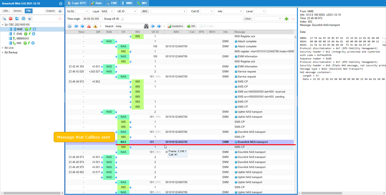
If you check the Downlink NAS transport message, you can see the NAS message that carries the SMS payload from the network back to the UE. In this example, this downlink message corresponds to the SMS delivery notice or echoed SMS sent from the Callbox SMS server to the UE.
In the selected log, the message is Downlink NAS transport and the detailed view shows that it is an EMM message with Protocol discriminator = 0x7, EPS Mobility Management, and Message type = 0x62, Downlink NAS transport. The NAS message container includes the SMS-related payload that is delivered to the UE through NAS signalling.
Note that the NAS log shows the NAS transport layer and the raw NAS container data, but it does not show the decoded SMS text in this view. To check the decoded SMS information, such as the source number, destination number, and message text, you should check the corresponding IMS log entry around the same transaction. In Amarisoft Callbox, the IMS server log is also used as the SMS center log for this test, so it provides the decoded SMS information while the NAS log confirms the actual NAS transport path.
Test 2 : MT SG-SMS
This is to show how to configure and test MT (Mobile Terminated) SMS over SG (NAS message).
Configuration
I used the enb.default.cfg (LTE default configuration) as it is without changing any contents in it.

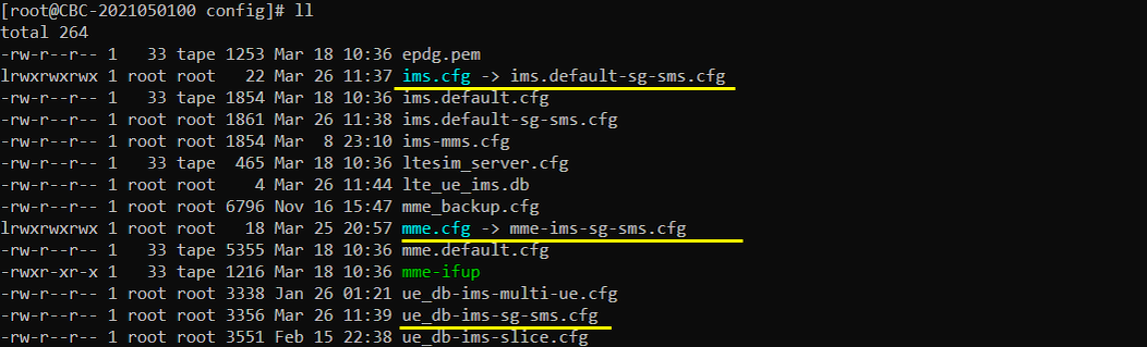
I also used the ims.default-sg-sms.cfg that is copied and modified from ims.default.cfg, mme-ims-sg-sms.cfg that is copied from mme-ims.cfg and ue_db-ims-sg-sms.cfg that is copied from ue_db-ims.cfg.
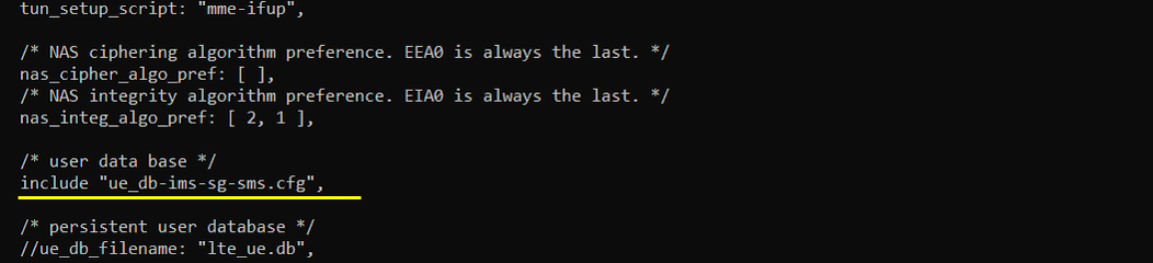
In mme-ims-sg-sms.cfg file, you would notice that ue_db-ims-sg-sms.cfg is used as ue db.
In this example, the MME configuration uses ue-db-ims-sg-sms.cfg as the UE database, as shown by include "ue-db-ims-sg-sms.cfg". This means that the UE subscription information for this MT SG-SMS test is taken from ue-db-ims-sg-sms.cfg.
This is important because the MT SMS is triggered from the network side and delivered to the UE based on the telephone number configured in the UE database. Therefore, the IMSI, authentication parameters, and tel number in ue-db-ims-sg-sms.cfg should match the USIM and the destination number used for the test.
The other parameters shown here are general MME settings. tun_setup_script: "mme-ifup" is used for PDN network interface setup, nas_cipher_algo_pref defines the NAS ciphering algorithm preference, and nas_integ_algo_pref defines the NAS integrity algorithm preference. These parameters are not specific to MT SG-SMS, but they are required for normal LTE attach and NAS signalling operation before the Callbox can deliver SMS to the UE.
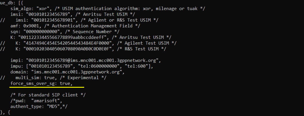
In this tutorial, I am using an Amarisoft Test USIM. In ue-db-ims-sg-sms.cfg, check that the IMSI and authentication parameters match the USIM being used by the UE. In this example, imsi: "001010123456789" and K: "00112233445566778899aabbccddeeff" are configured for the Anritsu Test USIM, so the UE can complete authentication and LTE attach successfully.
Also check the impu field and remember the tel numbers configured there. In this example, the UE has tel:0600000000 and tel:600 configured as public user identities. These telephone numbers are used by the Callbox SMS server when sending SMS to the UE, so the destination number used for the MT SMS test should match one of these tel values.
For this MT SG-SMS test, force_sms_over_sg: true is configured. This parameter forces the Callbox to use SG-SMS instead of IMS SMS when sending SMS to this UE. This is important because the UE database still includes IMS-related fields such as impi, impu, and domain, and without forcing SG SMS the Callbox may choose the IMS SMS path depending on the registration status and service configuration. By setting force_sms_over_sg: true, the MT SMS generated from the Callbox side is delivered through the SG-SMS path using NAS signalling, which is the behavior we want to verify in this test.
Perform the test
Start the LTE service and check the basic cell configuration. For MT SG-SMS, there is no special LTE radio configuration requirement. Any normal LTE cell configuration is acceptable as long as the UE can camp on the LTE cell, complete attach, and remain registered so that the Callbox can deliver the SMS to the UE.
In this example, cell phy shows that the LTE cell is running with PLMN 00101 and eNB ID 0x1a2d0. The cell is configured as LTE Band 7 with 5 MHz bandwidth, downlink ARFCN 3350, uplink ARFCN 21350, and normal LTE numerology parameters. These values are not specific to SG-SMS, but they confirm that the LTE cell is active and ready for UE registration.
After confirming the cell configuration, power on the UE and make sure the UE attaches successfully. Once the UE is registered and the UE database is configured with force_sms_over_sg: true, you can trigger the MT SMS from the Callbox side and verify that the UE receives the SMS through Downlink NAS transport rather than through IMS SMS.

Power On UE and make it sure that UE get registerred. (
You can confirm the registration status from the MME screen using the ue command. In this example, the UE with SUPI 001010123456789 is registered to EPC, REG is Y, TAC is 0x1, and two bearers are assigned. The IP address field shows multiple IP addresses, for example 192.168.3.2 and 192.168.4.2, and it also shows an IPv6 prefix. This indicates that the UE has established more than one PDN connection.
In my device, two IP addresses are assigned, one for the Internet APN and the other for the IMS APN. For this MT SG-SMS test, this does not matter because force_sms_over_sg: true is configured in the UE database. This forces the Callbox to send the SMS through SG-SMS even if the UE also has an IMS PDN. Therefore, unlike the MO SG-SMS test where it is better to avoid IMS registration to prevent the UE from choosing SMS over IMS, the MT test can still verify SG-SMS as long as the Callbox side is configured to force SMS over SG.

Check the registered user in (ims) screen. (
In this example, the IMS screen shows the IMPI [001010123456789@ims.mnc001.mcc001.3gppnetwork.org](mailto:001010123456789@ims.mnc001.mcc001.3gppnetwork.org) and SIP Binding information. This means that my phone completed IMS registration, so the IMS server shows the SIP URI, IMEI, registration expiry time, supported options such as sms and volte, and the IMPU values including tel:0600000000 and tel:600.
Note that IMS registration is not mandatory for SG-SMS itself. In this MT SG-SMS test, the important point is that the user is known to the Callbox SMS server and that the tel number is registered or configured correctly. If you see only the IMPI without SIP Binding information, it can still be enough for this test as long as the UE is attached to LTE and force_sms_over_sg: true is configured in the UE database. With force_sms_over_sg: true, the Callbox sends the MT SMS through the SG-SMS path using NAS signalling rather than choosing IMS SMS.

Send SMS from (ims) and confirm that you get the message on UE. (
In this example, the command sms 0600000000 "MT SMS over SG - 0600000000" is used. The first parameter, 0600000000, is the destination telephone number, and it should match one of the tel numbers configured for the UE in ue-db-ims-sg-sms.cfg. The text inside the quotation marks is the SMS message body that will be delivered to the UE.
Note that receiving the SMS on the UE screen only confirms that the SMS delivery was successful from the user point of view. It does not by itself prove whether the SMS was delivered over SG-SMS or over IMS SMS. To verify that the message was actually sent over SG-SMS, you should check the WebGUI log and confirm that the message is carried by Downlink NAS transport and SMS-CP messages rather than by IMS SIP MESSAGE signalling. Since force_sms_over_sg: true is configured in this test, the expected result is that the MT SMS is delivered through the NAS-based SG-SMS path.

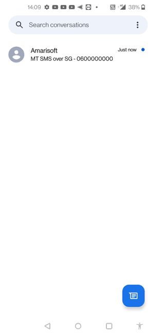
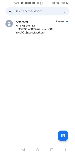
The UE receives the SMS as shown on the phone screen. In this example, the sender is displayed as Amarisoft and the message body is MT SMS over SG - 0600000000, which is the same text sent from the IMS screen command.
This confirms that the MT SMS was successfully delivered to the UE from the Callbox side. However, this phone screen alone only confirms successful SMS reception. It does not prove the transport path. To confirm that this SMS was delivered over SG-SMS, you should check the WebGUI log and verify that the message is carried by Downlink NAS transport and SMS-CP messages. Since force_sms_over_sg: true is configured in the UE database, the expected log result is that the Callbox sends this MT SMS through the NAS-based SG-SMS path rather than IMS SIP MESSAGE.
Now let’s try again using the IMPI instead of the tel number in the SMS message body. In this example, the destination address of the sms command is still 0600000000, but the message text includes the IMPI value 001010123456789@ims.mnc001.mcc001.3gppnetwork.org.
This is useful to confirm that the MT SMS can be generated from the Callbox side using the same destination telephone number while changing only the message content. The IMPI shown in the message body is not used as the SMS routing address in this command. It is just part of the SMS text delivered to the UE. The actual routing target is still the first parameter of the command, 0600000000, which should match the tel number configured for the UE.
After sending this command, check the UE screen to confirm that the new SMS is received, and then check the WebGUI log to verify that it was delivered through Downlink NAS transport and SMS-CP. The UE screen confirms delivery, while the log confirms whether the delivery path was SG-SMS rather than IMS SMS.

The UE receives the second MT SMS as shown on the phone screen. The message body contains the IMPI value 001010123456789@ims.mnc001.mcc001.3gppnetwork.org, which confirms that the SMS text sent from the Callbox command was delivered to the UE correctly.
Again, this screen only confirms that the SMS was received by the UE. It does not confirm the transport path by itself. To verify that this message was delivered over SG-SMS, check the WebGUI log and confirm that the MT SMS is carried by Downlink NAS transport and SMS-CP messages. In this test, force_sms_over_sg: true is configured, so even though the command is executed from the IMS screen and the UE may have IMS registration, the Callbox should still deliver the SMS through the SG-SMS path using NAS signalling.
Log Analysis
Enable at least NAS, SIP, and IMS logs in the WebGUI log viewer. For easier analysis, you can filter the log with NAS, SIP, and IMS. Even though this test is intended to use SG-SMS rather than IMS SMS, the IMS log should still be enabled because the Amarisoft IMS server is also acting as the SMS center in this setup.
In this sample log, the MT SMS is first generated from the IMS screen command. The highlighted IMS log shows SMS src=Amarisoft dst=0600000000: sending, and the right-side detail window shows the message text as text="MT SMS over SG - 0600000000". This confirms that the Callbox SMS server generated the SMS toward the UE whose destination number is 0600000000.
After the SMS is generated, the UE may be in idle state, so the network first triggers paging and RRC connection establishment. In the log, you can see Paging, followed by RRC connection request, RRC connection setup, and RRC connection setup complete. After the RRC connection is established, the UE sends a Service request, and the network proceeds with security and radio bearer setup using Security mode command, Security mode complete, RRC connection reconfiguration, and RRC connection reconfiguration complete.
Once the UE is connected, the actual MT SMS is delivered through Downlink NAS transport. This is the important part for verifying SG-SMS. The Downlink NAS transport message carries the SMS-CP payload from the network to the UE over NAS signalling. This confirms that the SMS delivery path is NAS-based SG-SMS rather than IMS SIP MESSAGE.
After receiving the downlink SMS, the UE sends responses back to the network. These are shown as Uplink NAS transport messages and SMS-CP messages. These uplink messages correspond to the UE acknowledgement and SMS protocol response for the delivered MT SMS. Therefore, for one MT SMS, the expected log flow is SMS server sending event, paging and RRC connection establishment if the UE is idle, Downlink NAS transport carrying the SMS to the UE, and Uplink NAS transport carrying the UE response back to the network.

RRC / NAS Signaling
Uplink NAS transport
: This is the Uplink NAS transport message sent by UE to carry SMS message. (
Message: Uplink NAS transport
Protocol discriminator = 0x7 (EPS Mobility Management)
Security header = 0x2 (Integrity protected and ciphered)
Auth code = 0x6cbb8aab
Sequence number = 0x0d
Protocol discriminator = 0x7 (EPS Mobility Management)
Security header = 0x0 (Plain NAS message, not security protected)
Message type = 0x63 (Uplink NAS transport)
NAS message container:
Length = 168
Data = .... (
Downlink NAS transport
: This is the Uplink NAS transport message sent by Network to carry SMS message. (
Downlink NAS transport
Data:
Protocol discriminator = 0x7 (EPS Mobility Management)
Security header = 0x2 (Integrity protected and ciphered)
Auth code = 0x040c1d94
Sequence number = 0x0c
Protocol discriminator = 0x7 (EPS Mobility Management)
Security header = 0x0 (Plain NAS message, not security protected)
Message type = 0x62 (Downlink NAS transport)
NAS message container:
Length = 170
Data = .... (