LTE Roaming
The purpose of this tutorial is to show you how to perform Roaming Tests with LTE network.
This tutorial shows how to test Cell Reselection on Amari Callbox and a commercial UE. Cell Reselection is a mechanism where UE can change the cell in Idle mode. The idle mode cell change happens in several different situations as listed below. When we say 'Cell Reselection', it usually mean the first two cases, but people say in a little different way depending on context.
- UE changes cell to another cell which has higher cell power with the same PLMN as the current cell.
- UE changes cell to another cell which has higher priorities. This priorities may be configured in SIB or RRC Release message.
- UE lost signal from the current cell and change to another cell with selectable cell. Strictly speaking this is more like a cell selection, but it can be considered as a type of reselection.
- UE first attached to a visiting PLMN and changes to another cell with Home PLMN and vice versa. Strictly speaking this is called Roaming.
- UE attached to a cell and Network (eNB) explcitely direct UE to change to another cell via RRCConnectionRelease message. This is called Cell Redirection.
Table of Contents
Introduction
Cell Reselection and Roaming are core mechanisms in Long Term Evolution (LTE) networks, enabling User Equipment (UE) to optimize connectivity and maintain service continuity as radio and network conditions change. LTE, standardized by the 3rd Generation Partnership Project (3GPP), employs a layered architecture in which UEs interact with radio access nodes (eNodeBs) and core network entities to facilitate seamless mobility, efficient spectrum usage, and robust subscriber experiences. Cell Reselection governs the process by which an idle-mode UE autonomously selects the most suitable cell, based on parameters such as received signal quality, priority configurations, and PLMN (Public Land Mobile Network) identity. This process is crucial for maintaining coverage, optimizing battery life, and ensuring rapid service reacquisition. Roaming, on the other hand, allows UEs to access services outside their home network, involving identity management and inter-PLMN procedures. While the full roaming architecture includes complex inter-core interfaces (such as S6a between VPLMN and HPLMN MMEs), this tutorial focuses on the foundational aspects of cell reselection and basic roaming procedures from the radio and PLMN perspectives. By leveraging tools like the Amari Callbox and commercial UEs, practitioners can simulate and analyze these behaviors, gaining insight into LTE mobility management, network selection logic, and the interplay between system information broadcasts and UE decision-making. The significance of mastering these procedures extends from device validation and network optimization to ensuring compliance with global roaming standards, making this knowledge essential for engineers, testers, and network operators working within the LTE ecosystem.
-
Context and Scope
- This tutorial addresses LTE mobility management, specifically focusing on cell reselection and roaming behaviors using Amari Callbox and a commercial UE.
- It explores how UEs autonomously select and switch cells in idle mode, examines the criteria influencing these decisions, and explains the limited-scope roaming tested here, distinct from full core network roaming architecture.
- The content is relevant for radio interface validation, device testing, and understanding fundamental LTE mobility procedures.
-
Relevance and Importance
- Understanding cell reselection is vital for optimizing network performance, improving user experience, and ensuring device interoperability in multi-cell and multi-PLMN environments.
- Roaming procedures covered here are foundational for confirming device readiness for international or multi-operator deployment, even if the full core roaming architecture is out of scope for this exercise.
- Mastery of these mechanisms supports efficient troubleshooting, network planning, and standards compliance.
-
Learning Outcomes
- Gain practical experience in setting up and executing LTE cell reselection and roaming tests using a controlled test environment.
- Comprehend the architectural roles of eNodeB, PLMN, and UE in idle mode mobility and network selection.
- Interpret system information configurations (such as SIBs) and understand their impact on UE behavior.
- Recognize the limitations of radio-level roaming testing versus full core network roaming deployment.
-
Prerequisite Knowledge and Skills
- Familiarity with LTE architecture, including eNodeB, UE, PLMN, and mobility management concepts.
- Basic understanding of radio resource management, idle mode procedures, and system information broadcasts.
- Experience with radio network testing tools (e.g., Amari Callbox) and access to a compatible commercial UE.
- General technical proficiency in wireless communications and network protocol analysis is recommended.
Summary of the Tutorial
This tutorial outlines a procedure for testing LTE roaming between two PLMNs using a setup with one eNB supporting two PLMNs, two independently operating MMEs, and IMSs. The test focuses on verifying the UE's ability to roam between HPLMN and VPLMN cells and to observe the corresponding attachment and roaming behaviors.
-
Test Setup:
- All network components (eNB, MMEs, IMSs) are launched automatically by the LTE service and are accessible via the 'screen' window.
- The eNB is configured to support two PLMNs, with each PLMN associated with a separate MME.
-
Configuration:
- The setup and configuration follow the guidelines from the Multiple MME tutorial, enabling support for multiple PLMNs and MMEs as depicted in the setup diagram.
-
Test Procedure:
- Start with the UE powered on. Disable Mobile Data for both HPLMN and VPLMN cells to allow the UE to enter and remain in the idle state, which is preferred for the roaming test.
- On the eNB screen, confirm that the UE initially attaches to Cell 1 (HPLMN).
- Turn off the HPLMN Cell, leaving only the VPLMN cell (ENB1) active.
- Wait for the UE to camp on to the VPLMN cell. This process may take a few minutes. Verify the presence of the roaming icon on the UE and confirm attachment to Cell 2 (VPLMN).
- Power on the HPLMN Cell again so that both HPLMN and VPLMN cells are active. The UE should still be registered to the VPLMN cell at this stage.
- Wait for the UE to detect and camp back to the HPLMN cell, typically requiring several minutes as the UE searches for the higher-priority HPLMN.
- Observe and confirm that the UE reattaches to Cell 1 (HPLMN) and the HPLMN icon is displayed on the device.
-
Log Analysis:
- Rather than analyzing individual protocol messages, log verification is performed by checking the cell attachment status across different stages of the test.
- Initially, confirm in the logs that the UE is attached to Cell 1 (HPLMN).
- After roaming, verify that the UE is attached to Cell 2 (VPLMN).
- Following reversion to the HPLMN, check that the UE is once again attached to Cell 1.
This methodology validates the UE's roaming capabilities between HPLMN and VPLMN environments and ensures correct cell attachment and roaming behavior through both direct observation and log verification.
Test Setup
In this tutorial, you may use two types of as shown below. All the components will launch automatically by lte service and all the components will be automatically added to 'screen' window as well.
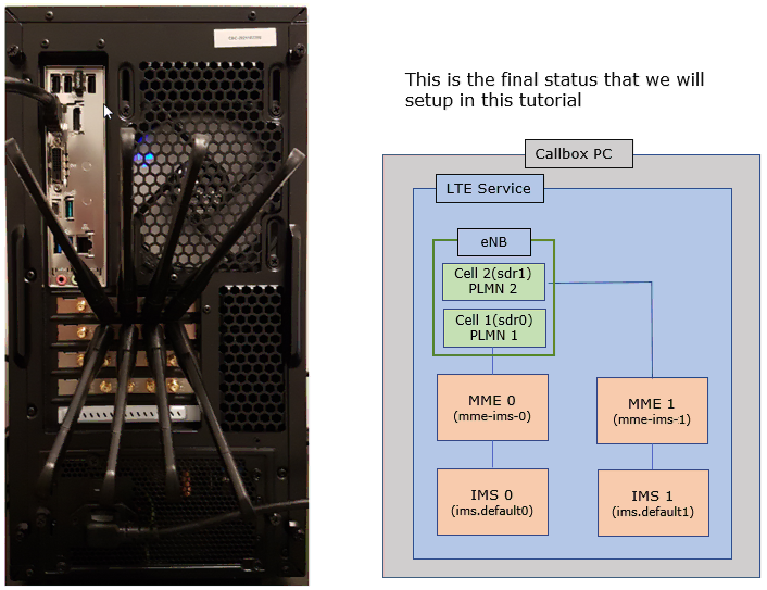
Everything runs on the one Callbox PC. The eNB carries both cells. Cell 1 is on sdr0 and broadcasts PLMN 1, Cell 2 is on sdr1 and broadcasts PLMN 2.
Each cell has its own core behind it. PLMN 1 goes to MME 0, started from mme-ims-0, and that MME sits in front of IMS 0 running ims.default0. PLMN 2 goes to MME 1 from mme-ims-1 with IMS 1 on ims.default1. The two chains never talk to each other. That is what makes one of them look like a visited network to the UE.
Cell 1 uses sdr0 and Cell 2 uses sdr1, so the two cells leave the box on different RF ports on the rear panel.
Configuration
For this tutorial, you can use two types of the setup as below.
: eNB with two PLMN, two MME and IMSs are running indepentaly as illustrated above, so configuration is pretty complicated. I used the exact same configuration as in the tutorial : Multiple MME.
Perform the test
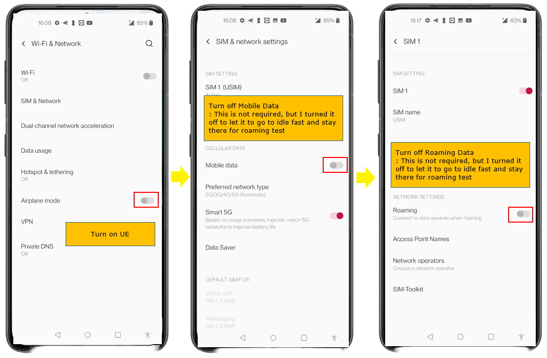
First with UE, power on UE and disable Mobile Data for both HPLMN cell and VPLMN Cell. (
There are three steps and they run left to right. Airplane mode has to be off so the modem is running at all. Wi-Fi is off here too, so the phone does not fall back to it while you wait.
The second step is Mobile data, under CELLULAR DATA in SIM & network settings. The third is Roaming, under NETWORK SETTINGS on the SIM 1 page. Both toggles go off.
The rest of the page is left alone. Preferred network type stays at 2G/3G/4G/5G (Automatic) and SIM 1 stays enabled. Turning the two data toggles off only stops user data. The phone still registers, and registration is all this test needs.
Go to [1 ENB] screen and confirm that UE attaches to Cell 1 (HPLMN).
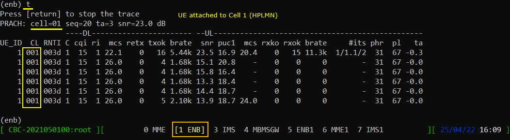
The t command starts the trace and [return] stops it again. The PRACH line above the table is the first thing to read. It says cell=01, so the random access came in on the first cell.
In the table the CL column is 001 on every row, which is the same cell said a second way. UE_ID is 1 and RNTI is 003d. pl is 67 dB and phr is 31, so the UE is close in and has plenty of transmit power left.
The screen list along the bottom is how you move between the components. MME, ENB, IMS, MBMSGW, ENB1, MME1 and IMS1 each have their own window, and [1 ENB] is the one in front here.
Now turn off HPLMN Cell. VPLMN cell (ENB1) remain active.
tx_gain takes a gain in dB and then a channel, so tx_gain 0 0 drops channel 0 to 0 dB. Leave the channel off and every cell is affected instead, which is not what you want here.
Running tx_gain with no arguments prints the current state. TX0 on port 0 is now at 0.0 dB while TX1 on port 1 is still at 89.8 dB. The PCIe SDR card runs from 0 to 89.75 dB, so those two values are the bottom and the top of its range.
The cell is not stopped, it is turned right down. That is enough for the UE to lose it, and it means you can bring the cell back later with one command instead of restarting anything.

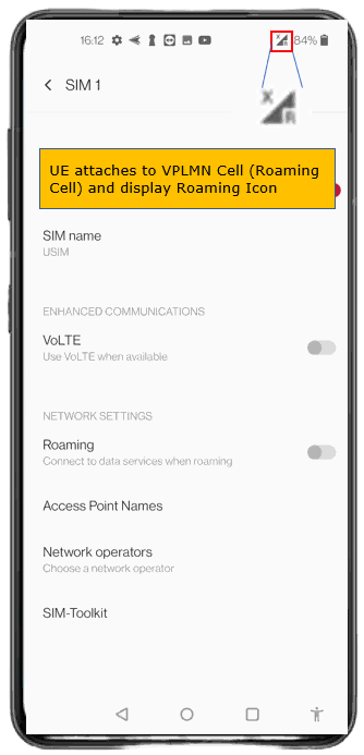
Make it sure that UE attaches to VPLMN cell. This takes a while (a few min) for UE to camp on to VPLMN Cell. You would see Roaming Icon displayed on the phone.
The icon to watch is the signal bar at the top of the screen. The small R beside it is what marks the roaming state.
The X on the bars is the data connection being down. That is expected here, because Mobile data and Roaming were both turned off before the test started.
The Roaming toggle further down the page is still off and it stays off. That switch controls whether data is carried while roaming. It does not stop the phone from registering on a visited PLMN, and registering is the part this test cares about.
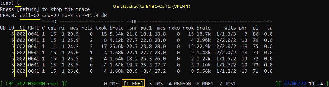
Confirm that UE attaches to Cell 2 (VPLMN).
The PRACH line now reads cell=02 and the CL column is 002 all the way down. UE_ID has moved on to 5 and the RNTI is 0041. Both change because this is a new connection on a different cell.
pl starts at 86 dB and settles around 71, against the 67 dB seen on the first cell. phr is down in the 7 to 19 range instead of 31. The UE is working harder on this cell.
snr sits between 15 and 28 dB across the rows, lower and more variable than before. That matches the higher pathloss.
Now power on HPLMN Cell gain. At this moment, both HPLMN and VPLMN cell are active and UE is registered to VPLMN Cell.
tx_gain 90 0 puts channel 0 back up. The card tops out at 89.75 dB, so asking for 90 gives you 89.8 in the readout. TX0 and TX1 now show the same value, which is the point of this step.
Nothing is done to the UE here. It stays on the VPLMN cell even though the HPLMN cell is back on the air. A UE in idle mode does not go looking for a higher priority PLMN straight away.

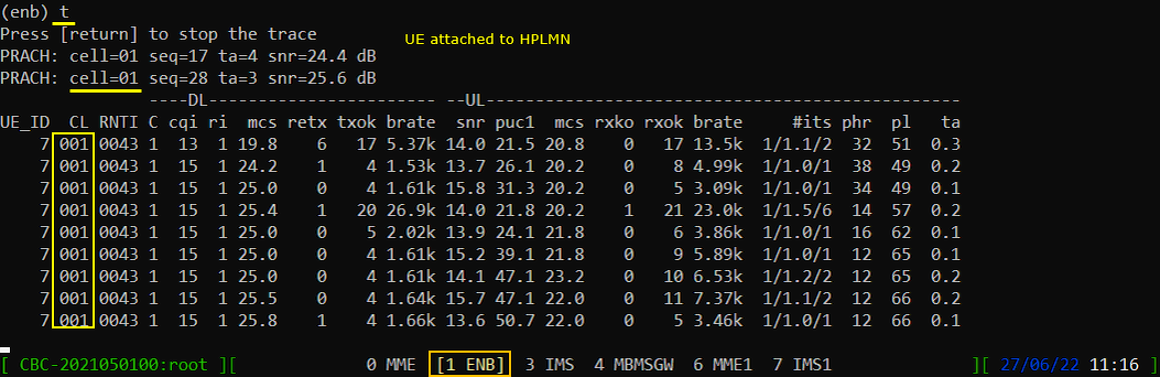
Wait until UE camp on to HPLMN Cell. This would take several minutes for UE to search for High Priority PLMN (HPLMN) cell.
There are two PRACH lines this time and both read cell=01. The UE came back to the first cell on its own, with nothing sent to it from the eNB side.
CL is 001 again, UE_ID is 7 and RNTI is 0043. Both identifiers have moved on from the earlier runs. That is how you tell this is a fresh connection rather than the old one resuming.
pl starts at 51 dB and drifts up to 66, and phr falls from 32 to 12 over the same rows. Against the 71 to 86 dB seen on the VPLMN cell, the UE is back on the closer of the two.
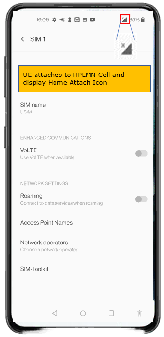
Now you would see the HPLMN icons on UE when it completes the attach to the HPLMN Cell.
The R that sat beside the signal bars has gone. That is the whole difference between this and the roaming state, and it is the quickest confirmation you can get without opening a log.
The X on the bars is still there and that is fine. Mobile data is still off from the first step, so the phone is registered but is not carrying user data.
Log Analysis
In this log, I would not look into any specific message. I will just take a look at a few blocks of messages to check to which cell the UE is connected.
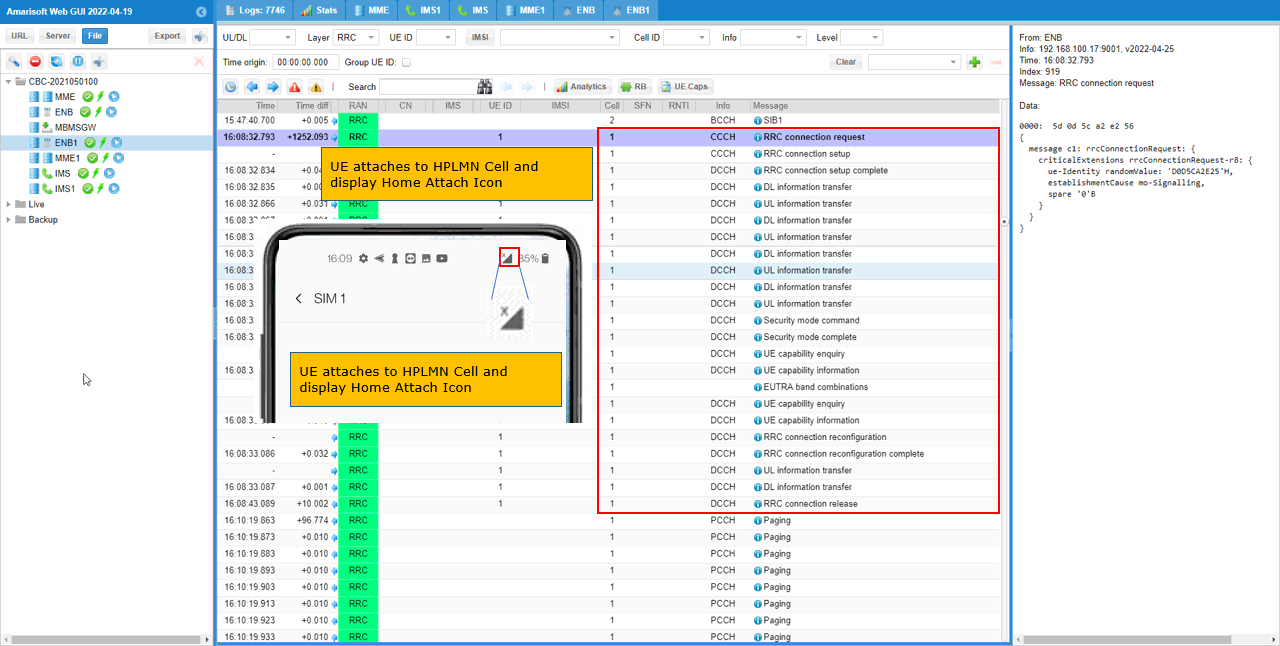
First, Confirm that UE is connected to the first cell (HPLMN Cell). You can identify the cell by checking the number in 'Cell' column.
The Layer filter is set to RRC, so only the signalling is listed and the whole attach fits on one page. The Cell column reads 1 on every row of the block.
The detail pane names the source as ENB on 192.168.100.17:9001. establishmentCause is mo-Signalling, which is the UE registering rather than asking for data. That fits, since Mobile data was turned off before the test started.
The block ends with an RRC connection release about 10 seconds in, and Paging on Cell 1 starts around 90 seconds later. That release is the UE going to idle, and idle is the state the rest of this test depends on.
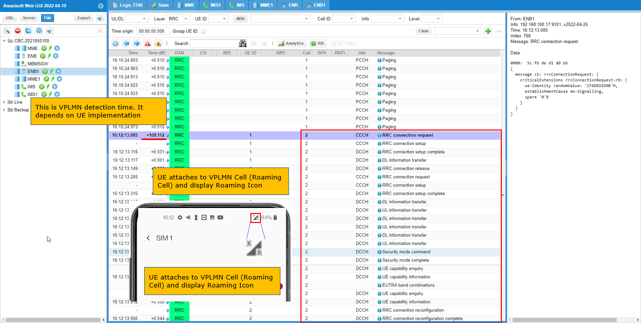
Once the UE is roamed to VPLMN cell, you should see that the UE is now connected to Cell 2.
The time difference on the first row of the block is +108.112. Just under two minutes passed between the last Paging on Cell 1 and the UE turning up on Cell 2. How long this takes is down to the UE, not to anything you set on the eNB, so do not expect the same number from a different handset.
The detail pane names the source as ENB1 on 192.168.100.17:9101, a different port from the Cell 1 attach. establishmentCause is mo-Signalling again.
There are two RRC connections here, not one. The first is set up, carries a single DL information transfer and is released within about 200 ms. The second runs the full sequence through security mode, capability exchange and reconfiguration. Filter on the Cell column alone and you can easily miss the first one.
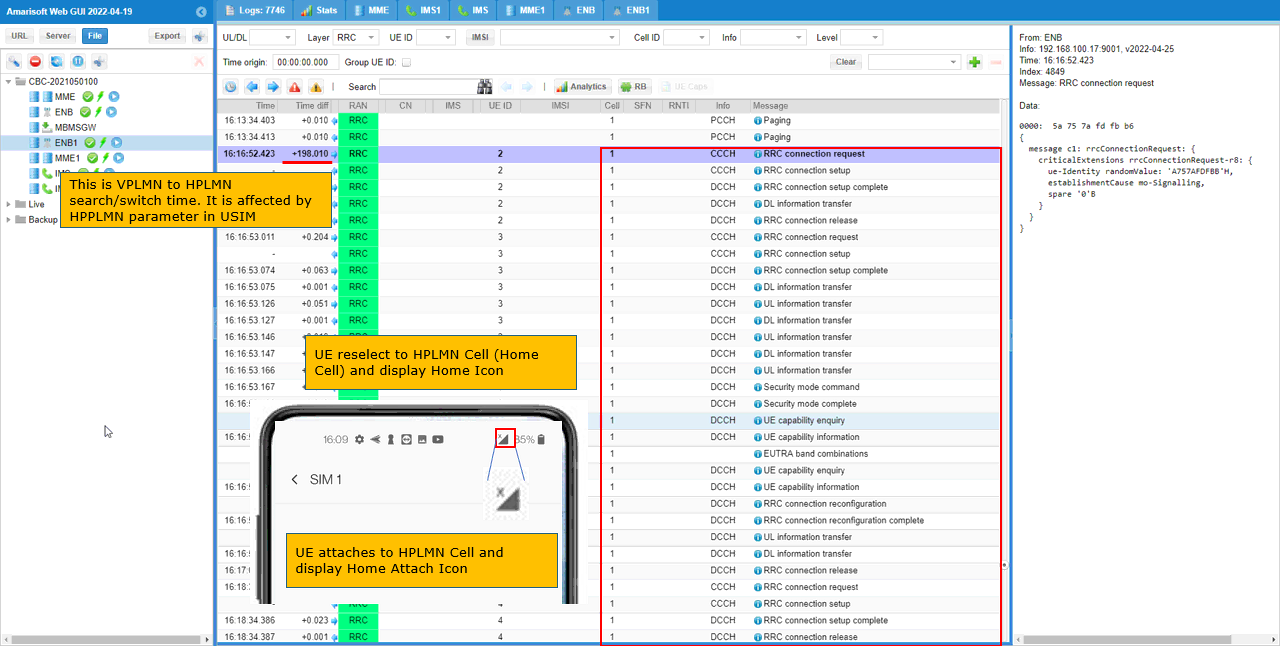
After roaming back to HPLMN cell, you should see that UE is attached to Cell 1.
The time difference is +198.010, so a little over three minutes passed before the UE went back. That interval is affected by the HPPLMN parameter in the USIM, so it is a property of the SIM card rather than something you set on the Callbox.
The detail pane is back to ENB on 192.168.100.17:9001, the same source as the very first attach. The Cell column reads 1 again for the whole block.
The same two connection pattern turns up here. UE ID 2 connects and is released almost at once, then UE ID 3 carries the full registration through to reconfiguration. A third short connection follows at 16:18:34 under UE ID 4.