
LTE PDSCH/PUSCH Resource Allocation
The purpose of this tutorial is to show you how to allocate resources for PDSCH/PUSCH manually instead of letting gNB/eNB automatically schedule them depending on the situation (e.g, depending on amount the data from higher layer, radio link quality etc).
In default configuration, Amarisoft eNB/gNB schedule PHY/MAC resources automatically based on various factors like IP layer throughput and radio link quality (e.g, amount of CRC(i.e, retx), CSI report from UE (i.e, CQI, RI), phr report from UE). But sometimes you may want to allocate the PHY/MAC resources as you like regardless of other conditions mentioned above. You can specify following PHY / MAC resources manually as you want.
- RB Allocation : Start of RB and The number of RBs for each subframe for both PDSCH and PUSCH
- MCS : MCS for each subframe for both PDSCH and PUSCH
- I want to test the physical layer throughput at a specific condition (e.g, with a specific number of RBs and MCS) without using IP traffic tool (e.g, iperf etc)
- When I want to do some Radio Link Quality troubleshoot, I usually lower MCS manually until I get zero BLER (zero retx) in 't' command and then change connection enviorment (e.g, distance between UE and antenna, direction of antenna, antenna connection vs cable connection etc) and increase MCS step by step and see if any of those setup adjustment improve retx rate at a certain MCS
Table of Contents
- LTE PDSCH/PUSCH Resource Allocation
- Introduction
- Summary of the Tutorial
- Test Setup
- Key Configuration Parameters
- Test 1 : PDSCH Resource Allocation
- Test 2 : PUSCH Resource Allocation
- Configuration
- Perform the Test
- Log Analysis
- Sub Test 1 : PUSCH Resource Allocation with Fixed RB
- Sub Test 2 : PUSCH Resource Allocation with Fixed RB per Subframe
- Sub Test 3 : PUSCH Resource Allocation with Full RB
- Tips
Introduction
Manual resource allocation for Physical Downlink Shared Channel (PDSCH) and Physical Uplink Shared Channel (PUSCH) in cellular networks offers granular control over PHY/MAC layer parameters, bypassing the typical dynamic scheduling performed by the gNB (5G NR base station) or eNB (LTE base station). In standard operational scenarios, Amarisoft eNB/gNB automatically manages resource distribution based on real-time metrics such as IP layer throughput, link adaptation feedback (e.g., Channel Quality Indicator (CQI), Rank Indicator (RI)), Power Headroom Reports (PHR), and Hybrid Automatic Repeat Request (HARQ) statistics (e.g., CRC and retransmissions). However, there are use cases where direct manual intervention is desirable—such as precise throughput benchmarking, radio link quality troubleshooting, or customized test scenarios. By specifying parameters like Resource Block (RB) allocation (defining the start RB and number of RBs per subframe) and Modulation and Coding Scheme (MCS) for each subframe, engineers and researchers can simulate specific radio conditions, bypass upper-layer traffic generators, and systematically analyze performance at the physical layer. This approach is crucial for validating PHY/MAC implementations, optimizing link adaptation strategies, and isolating variables in controlled test environments. Manual resource configuration thus plays a significant role in R&D, performance tuning, and quality assurance within the broader radio access network (RAN) ecosystem, complementing the automated, adaptive scheduling mechanisms that typically govern live networks.
-
Context and Technology Overview
- Amarisoft eNB/gNB platforms provide flexible, software-defined LTE and 5G NR base station functionality, supporting both automated and manual resource scheduling.
- PDSCH (downlink) and PUSCH (uplink) are the primary shared channels in LTE/NR, responsible for user data transmission, with resource allocation critical for throughput and reliability.
- Automated scheduling leverages radio feedback and higher-layer demands, while manual allocation allows explicit control over parameters such as RB assignment and MCS selection.
- Manual resource control is commonly used in R&D, conformance testing, and physical layer performance validation, providing a deterministic environment for experimentation.
-
Relevance and Importance of the Tutorial Topic
- Enables precise throughput measurement and benchmarking under known, reproducible radio conditions, without requiring IP traffic tools.
- Facilitates radio link troubleshooting by allowing stepwise adjustment of MCS and RB allocations to observe their impact on block error rate (BLER) and retransmissions.
- Supports advanced research, algorithm development, and root cause analysis by decoupling PHY/MAC behavior from adaptive scheduling mechanisms.
- Critical for validating device and network performance in controlled testbeds, prior to field deployment.
-
What Learners Will Gain
- Understanding of manual resource allocation mechanisms on Amarisoft eNB/gNB platforms.
- Practical skills in configuring RB and MCS parameters for both PDSCH and PUSCH on a per-subframe basis.
- Insights into PHY/MAC layer performance analysis, including methods for throughput and BLER optimization.
- Experience in setting up targeted experiments for radio link quality assessment and troubleshooting.
-
Prerequisite Knowledge and Skills
- Basic understanding of LTE/5G NR radio access network architecture and protocol stack, especially the PHY and MAC layers.
- Familiarity with Amarisoft eNB/gNB configuration and operational environment.
- Knowledge of key radio parameters: Resource Block (RB), Modulation and Coding Scheme (MCS), subframe structure.
- Experience with command-line tools and network testing methodologies is beneficial.
Summary of the Tutorial
This tutorial provides step-by-step procedures for manual allocation of PDSCH and PUSCH physical resources in LTE using Amarisoft configuration files, including several subtests exploring different resource allocation scenarios.
-
Test Setup:
- Low layer testing environment using a SIM card supplied with the system.
- No advanced IP configuration needed for these procedures.
-
Key Configuration Parameters:
- Manual resource allocation is controlled by parameters such as force_dl_schedule, force_full_bsr, pusch_fixed_rb_forced, pdsch_mcs, pdsch_fixed_rb_alloc, pdsch_fixed_rb_start, pdsch_fixed_l_crb, pusch_mcs, pusch_fixed_rb_alloc, pusch_fixed_rb_start, and pusch_fixed_l_crb.
-
Test 1: PDSCH Resource Allocation
-
Configuration:
- Use enb-pdsch-resources.cfg derived from enb.default.cfg.
- Set N_RB_DL to 100 for 20 MHz bandwidth.
- Manually configure PDSCH allocation using parameters: force_dl_schedule, pdsch_mcs, pdsch_fixed_rb_alloc, pdsch_fixed_rb_start, pdsch_fixed_l_crb.
-
Test Steps:
- Verify cell configuration with 'cell phy' and 'cell' commands.
- Start trace logging with the 't' command.
-
Log Analysis:
- Confirm resource allocation in log outputs and graphical RB plots.
- Observe that user traffic PDSCH allocation may be reduced if it shares a subframe with SIB PDSCH.
-
Sub Test 1: PDSCH Resource Allocation per Subframe
- Use enb-pdsch-resources-subframe.cfg.
- Configure PDSCH resource parameters as arrays to assign different resources per subframe.
- Visualize subframe-specific allocation using RB plots.
-
Configuration:
-
Test 2: PUSCH Resource Allocation
-
Configuration:
- Use enb-pusch-resources.cfg based on enb.default.cfg.
- Set N_RB_DL to 100 and force_full_bsr: true to schedule PUSCH in every possible UL subframe.
-
Test Steps:
- Validate cell configuration using 'cell phy' and 'cell'.
- Start trace logging using the 't' command.
-
Log Analysis:
- Check resource allocation through logs and RB map plots.
- Note that maximal RB allocation is constrained by PUCCH reservation and specific RB allocation rules.
-
Sub Test 1: PUSCH Resource Allocation with Fixed RB
- Use enb-pusch-resources-fixedRB.cfg.
- Allocate identical physical resources for each PUSCH transmission using single-value parameters.
- Ensure pusch_fixed_l_crb meets specific mathematical criteria (2a * 3b * 5c).
-
Sub Test 2: PUSCH Resource Allocation with Fixed RB per Subframe
- Use enb-pusch-resources-subframe.cfg.
- Assign different resources to each PUSCH subframe by configuring array values for parameters.
- Again, pusch_fixed_l_crb must comply with specific value criteria.
-
Sub Test 3: PUSCH Resource Allocation with Full RB
- Use enb-ul-full-rb.cfg.
- Enable pusch_fixed_rb_forced: true and set pusch_fixed_l_crb to maximum for the bandwidth.
- This config is intended for maximum UL throughput in single-UE scenarios, allocating all RBs including those typically reserved for PUCCH.
-
Configuration:
-
Tips: Interpretation of Resource Allocation Array in TDD
- Resource allocation arrays map to absolute slot/subframe numbers, not available slots only.
- Array elements corresponding to DL or special slots are ignored for PUSCH scheduling.
- Scheduling in special slots requires enabling the partial_slots parameter.
- In LTE, arrays are indexed by subframe; in NR, by slot (i.e., by TTI).
- A false in pusch_fixed_rb_alloc means eNB/gNB determines RBs dynamically, not that scheduling is stopped.
The tutorial guides users through the process of configuring and verifying manual resource allocation for both PDSCH and PUSCH, providing methodologies for both static and dynamic (per subframe) resource assignments, and clarifies interpretation of configuration arrays for TDD scenarios.
Test Setup
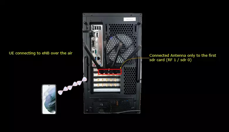
Test setup for this tutorial is as shown below. This is just for low layer testing, you may not need any complicated IP layer setup.
- SIM Card used in this tutorial is the one delivered with the system as it is.
- If you want to change the configuration, The tutorial Configuration Guide would help
Key Configuration Parameters
Followings are important configuration parameters for this tutorial. You may click on the items for the descriptions from Amarisoft documents.
- force_dl_schedule
- force_full_bsr
- pusch_fixed_rb_forced
- pdsch_mcs
- pdsch_fixed_rb_alloc
- pdsch_fixed_rb_start
- pdsch_fixed_l_crb
- pusch_mcs
- pusch_fixed_rb_alloc
- pusch_fixed_rb_start
- pusch_fixed_l_crb
Test 1 : PDSCH Resource Allocation
This test is to show how to allocates PDSCH resource manually in which you can allocate PDSCH resources in configuration file.
Configuration
The configuration shown here is common configuration for all the subtests belonging to Test 1 and I will not show this configuration repeatedly for every subtest.
I have used enb-pdsch-resources.cfg which is copied and modified from enb.default.cfg

I am using the default mme, ims config as shown below.

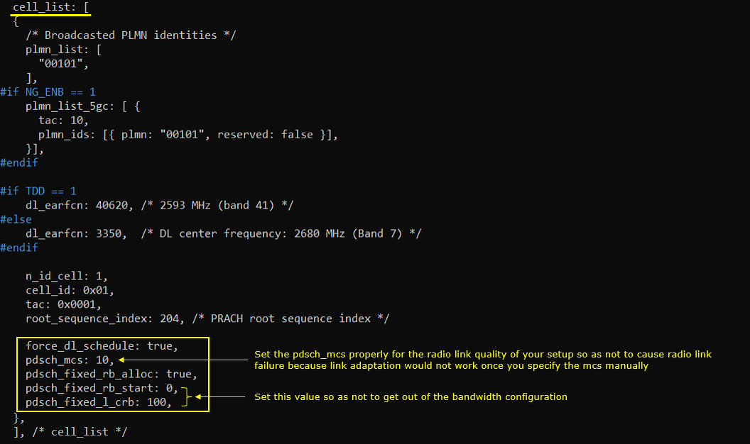
In enb-pdsch-resources.cfg, it is configured as follows.
N_RB_DL is set to 100, which means the LTE downlink bandwidth is configured as 20 MHz. This value defines the total number of downlink resource blocks available in the cell, and later PDSCH allocation will be selected within this 100 RB bandwidth. The configuration also sets TDD to 0, meaning FDD mode is used, N_ANTENNA_DL to 2, meaning 2x2 MIMO downlink transmission is enabled, N_ANTENNA_UL to 2 for two uplink antennas, CHANNEL_SIM to 0 meaning the channel simulator is disabled, and NG_ENB to 0 meaning this configuration is used for normal eNB operation rather than ng-eNB.

In the cell configuration, PDSCH resource allocation is forced manually by setting force_dl_schedule to true and pdsch_fixed_rb_alloc to true. force_dl_schedule: true makes the eNB schedule downlink transmission even when normal scheduler conditions may not naturally trigger the same allocation, and pdsch_fixed_rb_alloc: true tells the scheduler to use the fixed RB allocation values configured here. pdsch_mcs: 10 fixes the downlink MCS to 10, so you should choose this value according to the radio link quality of your setup because too high MCS can cause radio link failure or many retransmissions. pdsch_fixed_rb_start: 0 means the allocation starts from RB 0, and pdsch_fixed_l_crb: 100 means 100 contiguous RBs are allocated. Since N_RB_DL is also 100 in this example, the PDSCH allocation uses the full 20 MHz LTE downlink bandwidth, so the start RB and number of RBs must be chosen carefully so that the allocation does not exceed the configured cell bandwidth.
Perform the Test
Perform the test by first checking the cell configuration with cell phy and cell. In cell phy, confirm that the cell is running as LTE Band 7 with 20 MHz bandwidth, dl_arfcn 3350, two downlink antennas, two uplink antennas, 15 kHz subcarrier spacing, and 256QAM for downlink and 64QAM for uplink. In cell, confirm the same cell identity information such as cell ID 0x001, PLMN 00101, TAC 0x0001, PCI 1, PRACH root sequence index 204, and dl_arfcn 3350. This confirms that the cell has started with the intended basic radio configuration before checking the manually forced PDSCH scheduling behavior.

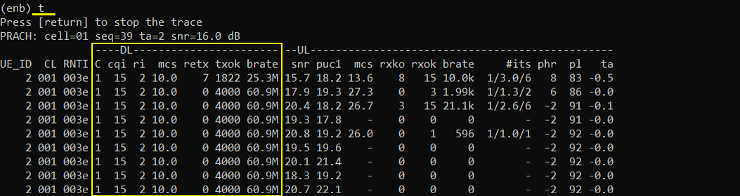
Start the trace log with the t command and check the downlink scheduling columns. In the DL part of the trace, mcs is shown as 10.0, which confirms that pdsch_mcs: 10 is being applied. The brate is shown around 60.9M after the initial transient line, which indicates that the downlink is being scheduled continuously with the configured fixed PDSCH condition. The retx value becomes 0 after the first line, meaning there is no downlink retransmission in this captured period, so the selected MCS appears to be stable for this radio condition. The cqi value is 15 and ri is 2, which indicates that the UE is reporting very good channel quality and rank 2 transmission capability, but the important point in this test is that the scheduler is using the manually configured PDSCH MCS and fixed allocation rather than adapting the resource allocation freely.
Log Analysis
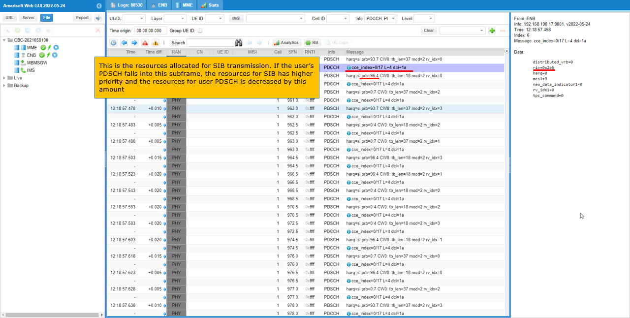
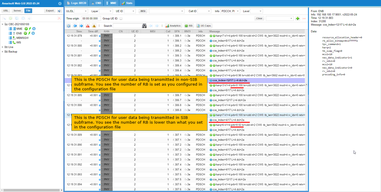
You can confirm the resource allocation both from the printed log text and from the graphical log view. In the WebGUI log view, filter the physical layer scheduling messages and check the PDSCH entries. For SIB PDSCH, harq is marked as si, which indicates that this PDSCH transmission is used for system information rather than normal user data. In the selected example, the detailed panel shows rv=0x2b5, harq=0, mcs=9, new_data_indicator=0, rv_idx=0, and tpc_command=0.
This SIB transmission also consumes downlink resources in the same subframe. Therefore, if user PDSCH is scheduled in a subframe where SIB PDSCH is also transmitted, the SIB has higher priority and the available resource for user PDSCH is reduced by that amount. This is why the actual user PDSCH allocation in the log may look slightly smaller than the manually configured full-band allocation in some subframes.
You can also check the user traffic PDSCH in the PHY log. Even though the number of RBs for user traffic PDSCH is configured to the maximum value, the actual allocation can be slightly reduced when it is transmitted in the same subframe as SIB PDSCH.
In the normal user PDSCH entry, the log shows rb=0:100, which means the user data PDSCH is allocated from RB 0 with 100 RBs as configured. In another subframe, the user PDSCH shows rb=8:92, which means the user data allocation starts from RB 8 and uses 92 RBs instead of the full 100 RBs. This reduction happens because part of the downlink resource is already occupied by SIB PDSCH in the same subframe. So the fixed PDSCH allocation setting should be understood as the intended user allocation, but the final actual allocation can still be adjusted when higher-priority channels such as SIB need to be transmitted.
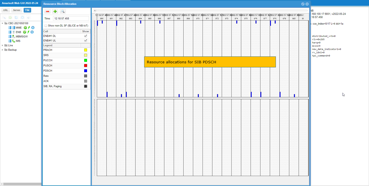
You can visualize the physical resource allocation for SIB PDSCH more easily by using the RB plot in Amarisoft WebGUI. In this view, the blue blocks indicate PDSCH resource allocation, and the selected time point shows the resources used for SIB PDSCH transmission. This graphical view is useful because it lets you see directly which RB region is occupied by SIB, paging, or other downlink control-related transmission, instead of checking only the text log. When this SIB PDSCH allocation appears in the same subframe as user traffic PDSCH, the user PDSCH allocation may be reduced accordingly because the SIB transmission has higher priority.
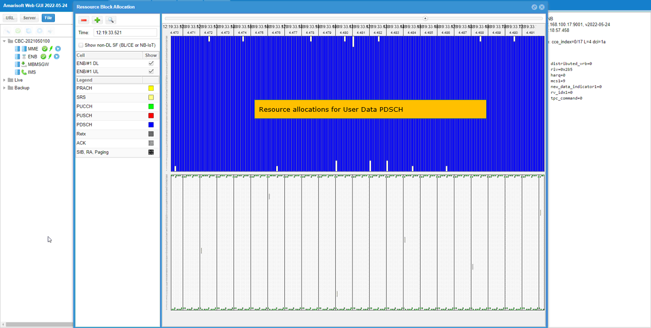
You can also visualize the physical resource allocation for user data PDSCH by using the RB plot. In this example, the blue region occupies almost the full downlink bandwidth, which matches the fixed PDSCH allocation configured with pdsch_fixed_rb_start: 0 and pdsch_fixed_l_crb: 100. This confirms visually that the user data PDSCH is being scheduled across the configured RB range. Compared with the SIB PDSCH case, the user data PDSCH allocation appears much wider because it is using the manually configured full-band allocation when there is no higher-priority downlink transmission reducing the available resource.
Sub Test 1 : PDSCH Resource Allocation per Subframe
This subtest shows how to allocate different physical resources for every subframe of PDSCH transmission.
I have used enb-pdsch-resources-subframe.cfg which is copied and modified from enb.default.cfg
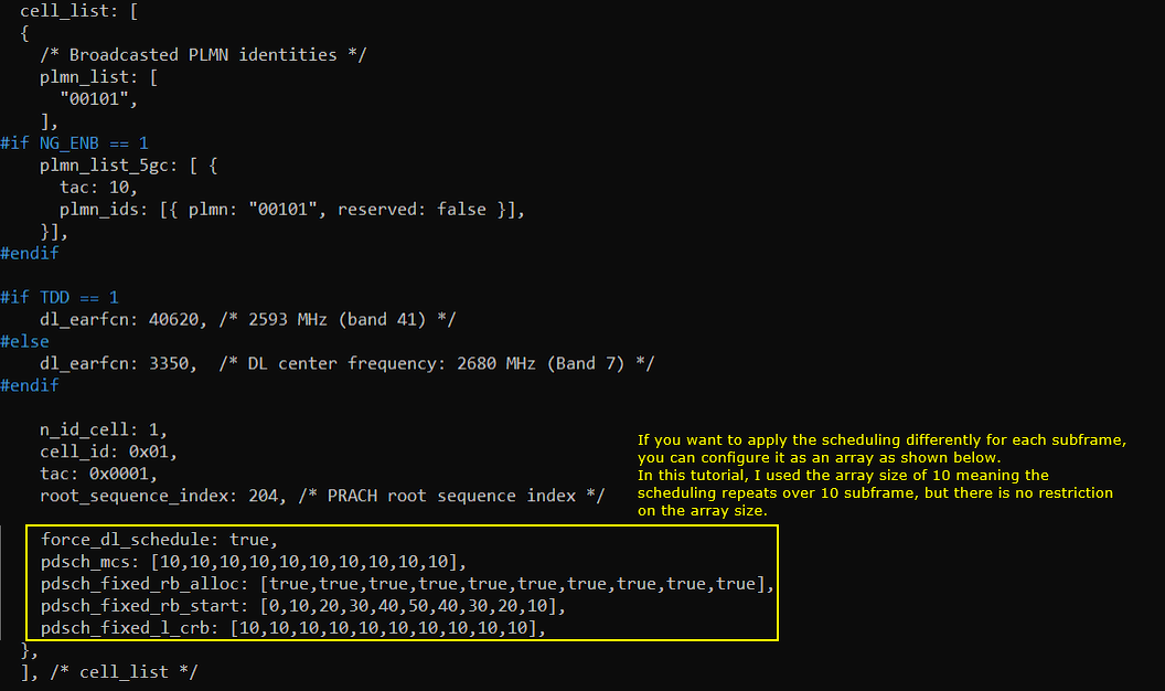
In this cell configuration, PDSCH resource allocation is still forced manually by setting force_dl_schedule to true and using pdsch_mcs, pdsch_fixed_rb_alloc, pdsch_fixed_rb_start, and pdsch_fixed_l_crb. The difference from the previous test is that these parameters are configured as arrays, so each element in the array applies to a different subframe.
In this example, pdsch_mcs is set to 10 for every subframe, so the MCS stays the same. pdsch_fixed_rb_alloc is set to true for every subframe, so fixed RB allocation is enabled continuously. pdsch_fixed_rb_start is configured as [0,10,20,30,40,50,40,30,20,10], which means the starting RB position changes from subframe to subframe. pdsch_fixed_l_crb is configured as [10,10,10,10,10,10,10,10,10,10], so each subframe uses 10 contiguous RBs. As a result, the PDSCH allocation moves across the bandwidth over time while keeping the same allocation size and MCS.
In this tutorial, the array size is 10, so the allocation pattern repeats every 10 subframes, but the array size itself is not limited to 10. This method is useful when you want to create a controlled PDSCH allocation pattern and observe how the resource position changes in the PHY log or RB plot.
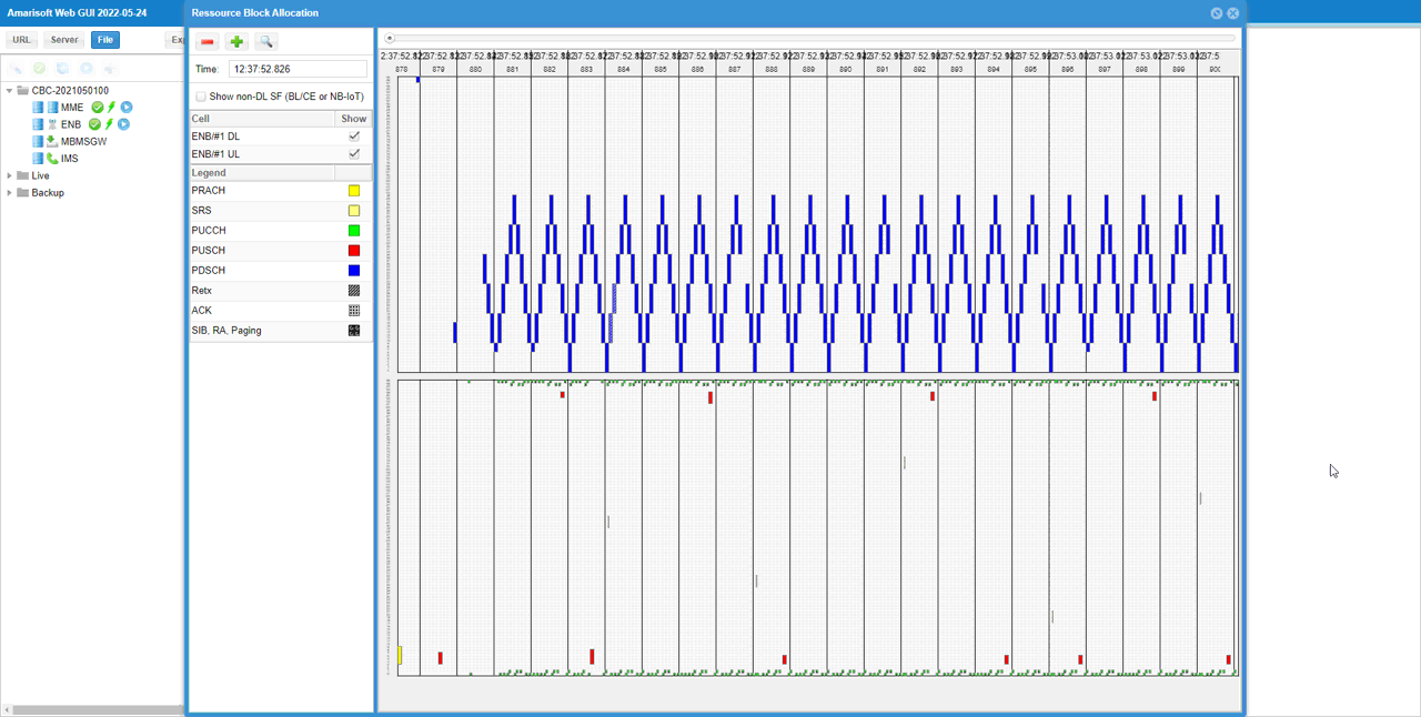
The allocated PDSCH resources in this subtest can be clearly visualized in the RB plot. The blue PDSCH blocks do not stay at one fixed RB position. Instead, they move across the bandwidth according to the pdsch_fixed_rb_start array configured in the cell configuration. Since pdsch_fixed_l_crb is set to 10 for every element, each allocation keeps the same width of 10 RBs, but the starting position changes per subframe.
This RB plot confirms that the per-subframe array configuration is applied as intended. The repeated stair-like pattern shows that the scheduler is not choosing the PDSCH RB position automatically, but following the manually configured RB start pattern repeatedly over time.
Test 2 : PUSCH Resource Allocation
This test is to show how to allocates PUSCH resource manually in which you can allocate PUSCH resources in configuration file.
Configuration
The configuration shown here is common configuration for all the subtests belonging to Test 1 and I will not show this configuration repeatedly for every subtest.
I have used enb-pusch-resources.cfg which is copied and modified from enb.default.cfg

I am using the default mme, ims config as shown below.
In enb-pusch-resources.cfg, it is configured as follows.
The bandwidth is set to 20 MHz by setting N_RB_DL to 100. Even though this test focuses on PUSCH, the LTE cell bandwidth is commonly defined by this resource block setting, and 100 RB corresponds to 20 MHz LTE bandwidth. In this configuration, TDD is set to 0, meaning FDD mode is used, N_ANTENNA_DL is set to 2 for 2x2 downlink MIMO, N_ANTENNA_UL is set to 2 for two uplink antennas, CHANNEL_SIM is set to 0 meaning the channel simulator is disabled, and NG_ENB is set to 0 meaning normal eNB operation is used rather than ng-eNB.
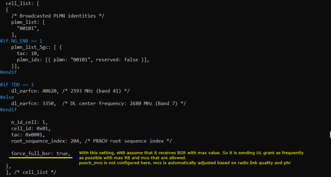
In this configuration, force_full_bsr: true is used to make the eNB schedule PUSCH as frequently as possible in every available uplink subframe. With this setting, the eNB behaves as if it always receives a maximum-value BSR from the UE, so it assumes that the UE always has uplink data waiting for transmission. As a result, the eNB keeps sending UL grants with the maximum RB allocation and MCS allowed by the current condition.
In this example, pusch_mcs is not configured manually, so the uplink MCS is still selected automatically. This means the scheduler can adjust the PUSCH MCS depending on radio link quality, PHR, and other uplink scheduling conditions, while force_full_bsr mainly forces continuous uplink scheduling rather than fixing the exact MCS value.
Perform the Test
Perform the test by first checking the cell configuration with cell phy and cell. In cell phy, confirm that the cell is running as LTE Band 7 with 20 MHz bandwidth, dl_arfcn 3350, two downlink antennas, two uplink antennas, 15 kHz subcarrier spacing, 256QAM for downlink, and 64QAM for uplink. In cell, confirm the same basic cell information such as cell ID 0x001, PLMN 00101, TAC 0x0001, PCI 1, PRACH root sequence index 204, and dl_arfcn 3350. This confirms that the LTE cell has started with the intended radio configuration before checking the PUSCH scheduling behavior.

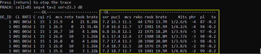
Start the trace log with the t command and check the UL part of the output. In this example, PUSCH is scheduled continuously, which confirms that force_full_bsr: true is working as intended. The uplink brate is shown around 13.7M to 20.8M, meaning uplink data transmission is being forced without using a separate uplink traffic tool.
Since pusch_mcs is not fixed in the configuration, the UL mcs value changes automatically, for example from 11.1 to 13.3, depending on the uplink radio condition and scheduler decision. The rxok value is much larger than rxko, so most uplink transmissions are successfully decoded, but there are still some failed receptions. The snr, puc1, phr, pl, and ta columns can be used together to understand the uplink link condition while the eNB keeps granting PUSCH as frequently as possible.
Log Analysis
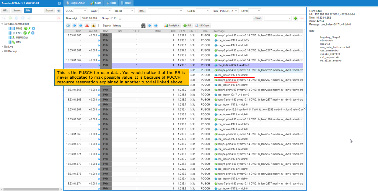
You can confirm the PUSCH resource allocation from the PHY log text. In the WebGUI log view, check the PUSCH entries and look at the rb field. In this example, the user data PUSCH is scheduled repeatedly because force_full_bsr: true makes the eNB assume that the UE always has uplink data to transmit.
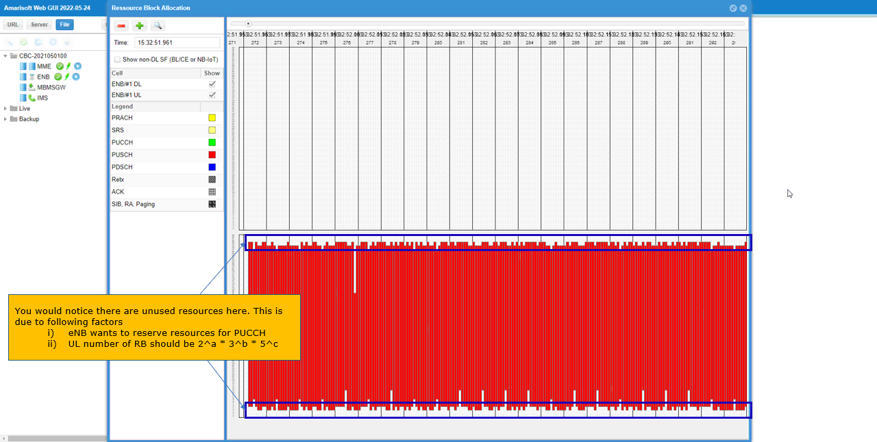
You may notice that the PUSCH RB allocation is not always the maximum possible value even though full-buffer uplink scheduling is forced. This is because some uplink resources are reserved for PUCCH and cannot be used for PUSCH. For example, the log shows PUSCH entries such as rb=4:90, meaning the allocation starts from RB 4 and uses 90 RBs, instead of occupying the full 100 RB bandwidth. So force_full_bsr can force frequent PUSCH grants, but the final PUSCH allocation still has to respect reserved uplink resources such as PUCCH.
You can also check the uplink resource allocation in the RB map. In this view, the red blocks indicate PUSCH allocation, and you can see that most of the uplink bandwidth is used continuously because force_full_bsr: true forces frequent uplink scheduling. However, some resource blocks near both edges of the frequency domain are not used for PUSCH.
This unused region appears mainly because the eNB reserves some uplink resources for PUCCH, so PUSCH cannot occupy the whole bandwidth. In addition, LTE uplink resource allocation has to satisfy the allowed DFT-s-OFDM allocation size rule, where the number of allocated RBs should be expressible as 2^a × 3^b × 5^c, with a, b, and c being zero or positive integers. Therefore, even when full-buffer uplink scheduling is forced, the final PUSCH allocation may still be slightly smaller than the full cell bandwidth.
Sub Test 1 : PUSCH Resource Allocation with Fixed RB
This subtest shows how to allocate same physical resources for every subframe of PUSCH transmission
I have used enb-pusch-resources-fixedRB.cfg which is copied and modified from enb.default.cfg
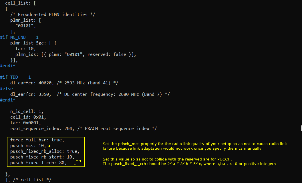
In this configuration, the same PUSCH resource allocation is applied to every PUSCH transmission by setting pusch_mcs, pusch_fixed_rb_alloc, pusch_fixed_rb_start, and pusch_fixed_l_crb as single values instead of arrays. force_full_bsr: true keeps forcing uplink scheduling, pusch_mcs: 10 fixes the uplink MCS to 10, and pusch_fixed_rb_alloc: true enables fixed RB allocation for PUSCH. pusch_fixed_rb_start: 10 means the PUSCH allocation starts from RB 10, and pusch_fixed_l_crb: 80 means 80 contiguous RBs are allocated for each PUSCH transmission.
You need to choose these values carefully. pusch_mcs should match the radio link quality of the setup because too high MCS can cause uplink decoding failure or retransmission. pusch_fixed_rb_start and pusch_fixed_l_crb should avoid the region reserved for PUCCH, especially near the band edges. Also, pusch_fixed_l_crb should satisfy the LTE uplink allocation size rule, where the number of RBs should be expressible as 2^a × 3^b × 5^c, with a, b, and c being zero or positive integers. In this example, 80 is valid because it can be expressed as 2^4 × 5.
The allocated PUSCH resources in this subtest can be checked in the RB map. The red blocks show the PUSCH allocation, and you can see that every PUSCH transmission is allocated with the same fixed RB range. This matches the configuration where pusch_fixed_rb_start is set to 10 and pusch_fixed_l_crb is set to 80.
Unlike the previous full-buffer scheduling case where the scheduler selected the uplink RB range automatically while avoiding reserved regions, this subtest fixes the PUSCH allocation explicitly. As a result, the RB map shows a stable and repeated PUSCH allocation pattern with the same number of RBs for each uplink transmission.
Sub Test 2 : PUSCH Resource Allocation with Fixed RB per Subframe
This subtest shows how to allocate different physical resources for every subframe of PUSCH transmission
I have used enb-pusch-resources-subframe.cfg which is copied and modified from enb.default.cfg
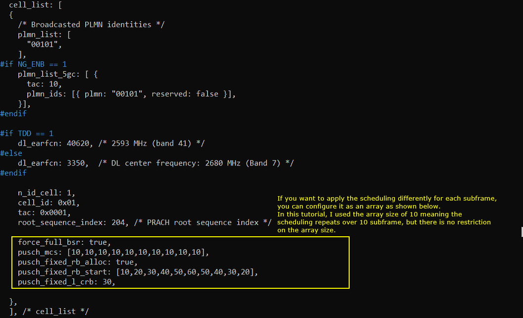
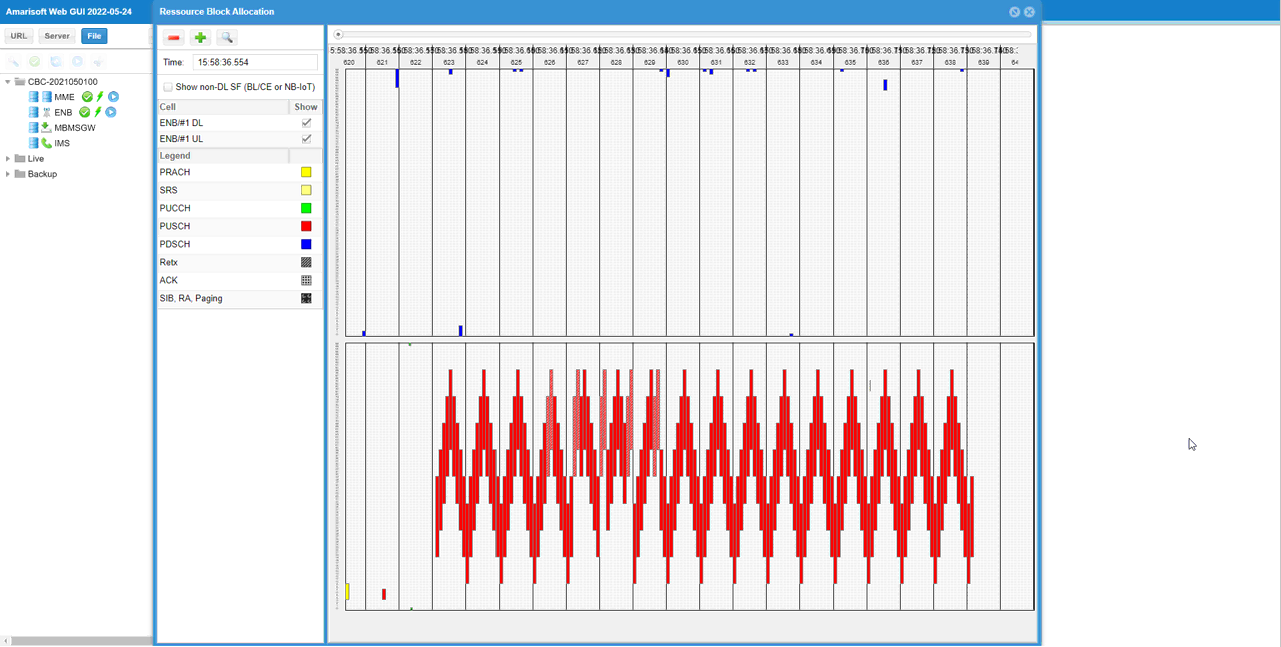
In this configuration, different PUSCH resource positions are applied to each PUSCH transmission by configuring the PUSCH parameters as arrays. force_full_bsr: true keeps uplink scheduling active, pusch_mcs is configured as [10,10,10,10,10,10,10,10,10,10], so the MCS is fixed to 10 for each element of the pattern, and pusch_fixed_rb_alloc: true enables fixed PUSCH RB allocation. pusch_fixed_rb_start is configured as [10,20,30,40,50,60,50,40,30,20], so the starting RB changes from subframe to subframe, while pusch_fixed_l_crb: 30 keeps the PUSCH allocation size fixed to 30 RBs.
In this tutorial, the array size is 10, so the scheduling pattern repeats every 10 subframes, but the array size itself is not restricted to 10. You should still choose the values carefully so that the PUSCH allocation does not collide with reserved PUCCH resources and so that pusch_fixed_l_crb satisfies the LTE uplink allocation size rule. In this example, 30 is valid because it can be expressed as 2 × 3 × 5.
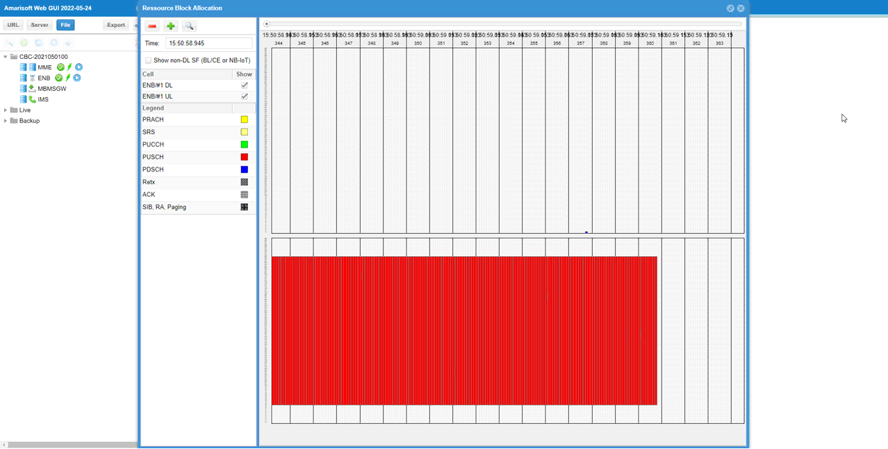
The allocated PUSCH resources in this subtest can be checked in the RB map. The red blocks show the PUSCH allocation, and you can see that the allocation position changes from subframe to subframe while keeping the same allocation size. This matches the configuration where pusch_fixed_rb_start is configured as an array and pusch_fixed_l_crb is set to 30.
This RB map confirms that the per-subframe fixed PUSCH allocation is applied as intended. The repeated moving pattern shows that the scheduler is following the configured RB start pattern instead of selecting the uplink RB position automatically, while the number of allocated RBs remains the same for each PUSCH transmission.
Sub Test 3 : PUSCH Resource Allocation with Full RB
This subtest shows how to allocate full physical resources for PUSCH. 'Full Physical Resource' mean the full UL RBs including the resources reserved for PUCCH. Main purpose of this configuration is to provide the maximun possible UL throughput as you can achieve from other callbox which supports single UE only. It implies that this configuration would work only when single UE is connected.
I have used enb-ul-full-rb.cfg which is copied and modified from enb.default.cfg
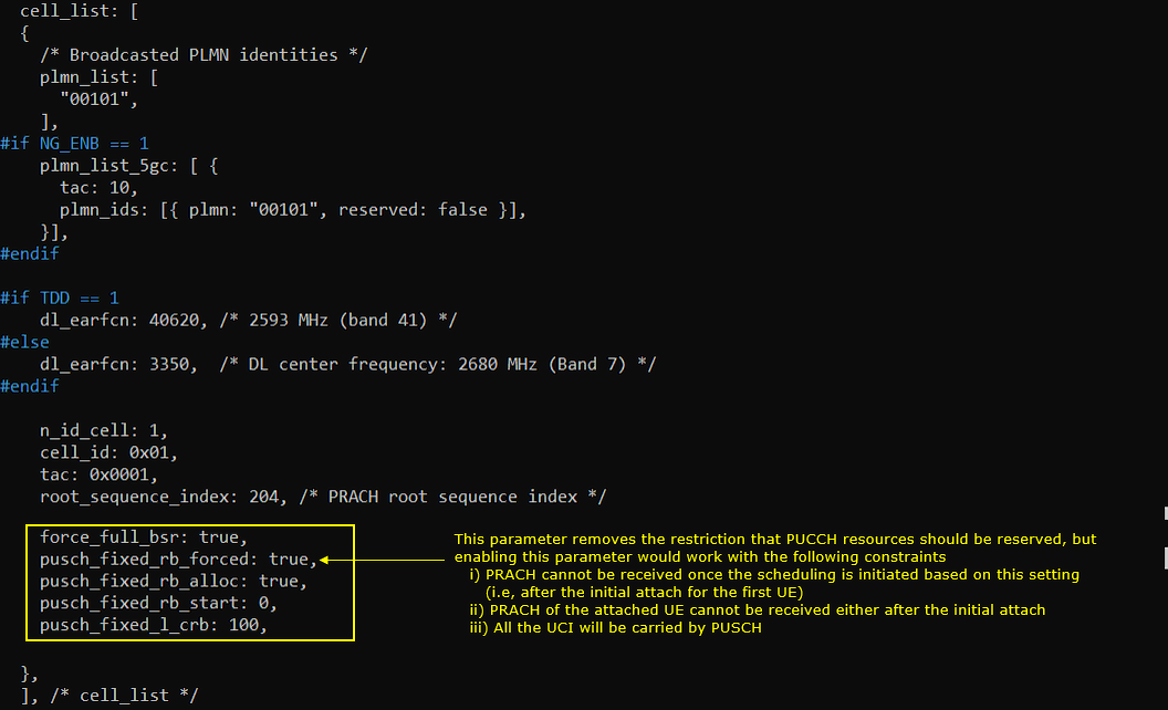
In this configuration, the same PUSCH resource allocation is applied to every PUSCH transmission by using single values for pusch_fixed_rb_alloc, pusch_fixed_rb_start, and pusch_fixed_l_crb. force_full_bsr: true keeps forcing uplink scheduling, pusch_fixed_rb_alloc: true enables fixed PUSCH RB allocation, pusch_fixed_rb_start: 0 starts the allocation from the first RB, and pusch_fixed_l_crb: 100 allocates the full 100 RB bandwidth.
The key parameter in this test is pusch_fixed_rb_forced: true. This setting removes the normal restriction that keeps some uplink resources reserved for PUCCH, so PUSCH can use the full RB range including the PUCCH-reserved area. However, this also means the configuration has important limitations. PRACH may not be received after this full-RB PUSCH scheduling starts, so initial attach is usually possible only for the first UE before the full scheduling behavior begins. PRACH from an already attached UE may also not be received, and UCI that would normally be carried on PUCCH will be carried on PUSCH instead. Therefore, this configuration is mainly useful for single-UE maximum uplink throughput testing, not for normal multi-UE operation.
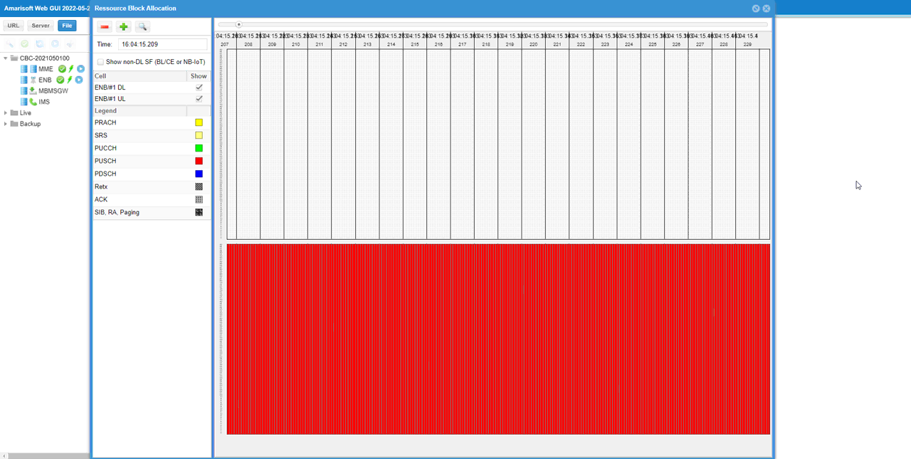
The allocated PUSCH resources in this subtest can be checked in the RB map. The red region occupies the full uplink bandwidth, which matches the configuration where pusch_fixed_rb_start is set to 0 and pusch_fixed_l_crb is set to 100. In this case, every PUSCH transmission is allocated with the full 100 RBs.
This result is different from the normal full-buffer PUSCH case because pusch_fixed_rb_forced: true allows PUSCH to use even the RB region that is normally reserved for PUCCH. As a result, the RB map shows continuous full-band PUSCH allocation, which is useful for maximum uplink throughput testing in a single-UE scenario.
Tips
Interpretation of Resource Allocation Array in TDD
It may be a little bit confusing to interpret the resource schedule array in TDD. So I want to clarify a few things with an example here. Note that this example is for PUSCH scheduling.
force_full_bsr: true,
pusch_fixed_rb_alloc: [ true,true,false,true,true,true,true,true,true,true ],
pusch_fixed_rb_start: [ 1,2,3,4,5,6,7,8,9,10],
pusch_fixed_l_crb: [ 11,12,13,14,15,16,17,18,19,20],
Let me explain a few things in Q&A form.
Q1 : Is the index of the array maps to absolute slot number ? or relative available slot ? For example, the 'false' (the third slot) of pusch_fixed_rb_alloc in this example mean 'slot #2 within the continguous 10 slots(size of the array)' or 'third available slot regardless of absolute position' ?
A1: It indicates absolute position. So the 'false' (the third slot) of pusch_fixed_rb_alloc in this example indicates the slot #2 of the contiguous 10 slots(size of the array)
Q2 : Then what would happen for the array index mapped to downlink slot ? For example, How the first element of pusch_fixed_rb_alloc, pusch_fixed_rb_start, pusch_fixed_l_crb of the array works (assuming that the first slot is configured as downlink in TDD pattern).
A2 : It is get ignored.
Q3 : What would happen for the array index mapped to special slot(partial slot) ?
A3 : PUSCH in partial slot is not scheduled in default configuration. If you want to schedule PUSCH in special slot (or special subframe), you need to set the parameter partial_slots
Q4 : Is value 0 in pusch_fixed_l_crb allowed ?
A4 : It is allowed for LTE, but not allowed in NR with this parameter. (
Q5 : What does each element in the array indicates ? Does it indicates 'slot' or 'subframe' ?
A5 : In LTE, it indicates 'subframe', in NR it indicates 'slot'. Simply put, it indicates a TTI.
Q6: what is the meaning of 'false' in pusch_fixed_rb_alloc ? For example, in this example pusch_fixed_rb_alloc: [ true,true,false,true,true,true,true,true,true,true ] what eNB/gNB would do at slot #2 ('false') ? does it stop PUSCH scheduling ? or it DOES schedule PUSCH with the best fit available RBs ?
A6 : It DOES schedule PUSCH with the best fit available RBs (