LTE MBMS
This tutorial is to show you how to configure and test MBMS. MBMS stands for Multimedia Broadcast/Multicast Service and it is technology designed to deliver broadcast or multicast content to multiple users simultaneously in a more efficient manner. It's especially useful for services like live TV, radio broadcasts, and other multimedia content that needs to be transmitted to a large number of users at once
Amarisoft supports MBMS by implementing a special gateway called MBMSGW. The key features of MBMSGW are
- It supports M1 Interface with GTP and SYNC Protocols
- It supports M2AP Protocol
- It allow users to configure Services and Multicast Components
- It has built-in RTP Packet Generator
Table of Contents
Introduction
Multimedia Broadcast/Multicast Service (MBMS) is a pivotal technology in modern mobile communication systems, enabling efficient delivery of multimedia content—such as live television, radio, and streaming services—to a large group of users simultaneously over cellular networks. Unlike traditional unicast methods where the same content is sent individually to each user, MBMS leverages broadcast and multicast transmission modes to optimize spectral efficiency and network resource utilization, making it highly suitable for mass media applications. The architectural framework of MBMS integrates specialized components such as the MBMS Gateway (MBMSGW), which orchestrates the distribution of multimedia data across the network. Amarisoft’s implementation of MBMS introduces a robust MBMSGW module that supports essential protocols including the M1 interface with GTP (GPRS Tunneling Protocol) and SYNC protocols for data transport synchronization, as well as the M2AP protocol for control signaling between the gateway and eNodeB or gNodeB. The MBMSGW further empowers operators to configure multiple services and multicast components, and includes a built-in RTP (Real-time Transport Protocol) packet generator to facilitate seamless end-to-end testing. MBMS thus plays a crucial role within the broader 3GPP ecosystem by enhancing delivery efficiency, reducing network load, and enabling advanced broadcast/multicast capabilities critical for next-generation mobile services.
-
Context and Background
- MBMS addresses the challenge of delivering identical multimedia content to large user groups without overloading network capacity.
- It is standardized by 3GPP and widely adopted in LTE and 5G architectures to support broadcast and multicast use cases.
- The MBMSGW acts as a central point for managing and distributing MBMS traffic, interfacing with both core and radio access network elements.
-
Relevance and Importance of the Tutorial
- This tutorial provides practical guidance on configuring and testing MBMS using Amarisoft’s MBMSGW, which is essential for operators, developers, and engineers involved in deploying or validating broadcast/multicast solutions.
- Understanding MBMS setup and testing procedures is crucial for supporting advanced media services and optimizing network performance in real-world deployments.
-
Learning Outcomes
- Gain a comprehensive understanding of MBMS architecture and key protocols (GTP, SYNC, M2AP) involved in multimedia broadcast/multicast delivery.
- Acquire hands-on knowledge of configuring MBMSGW, defining services and multicast components, and utilizing built-in RTP packet generation for test scenarios.
- Develop the ability to troubleshoot, validate, and optimize MBMS deployments in an Amarisoft environment.
-
Prerequisite Knowledge and Skills
- Familiarity with mobile network architectures, particularly LTE or 5G core and radio access network concepts.
- Understanding of IP-based networking and transport protocols (e.g., GTP, RTP).
- Basic experience with Amarisoft software tools and configuration methods is beneficial for following the tutorial effectively.
Summary of the Tutorial
This tutorial demonstrates the procedure for low-layer testing of LTE MBMS (Multimedia Broadcast Multicast Service) broadcasting from an eNB without any UE connection. The focus is on system configuration, service setup, and network-side verification of broadcast data transmission.
- Test Setup
- Two setup options are described:
- Setup A: Uses a commercial UE as the Device Under Test (DUT).
- Setup B: Uses Amarisoft UEsim as the DUT. The tutorial proceeds with Setup B.
- Two setup options are described:
- Key Configuration Parameters
- Configuration involves several key parameters and blocks:
- mbms block in the eNB configuration, specifying parameters such as sib13_periodicity, synchronization_area_id, service_area_id_list, and notification_config (with repetition coefficient, offset, and subframe index).
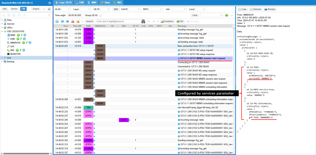
- services in the MBMS gateway configuration, including fields for tmgi, plmn, service_id, service_area_id, session_id, gtp_addr, gtp_teid, scheduling details, and traffic components (IP addresses, interface addresses, simulation flags, RTP payload length, and bitrate).
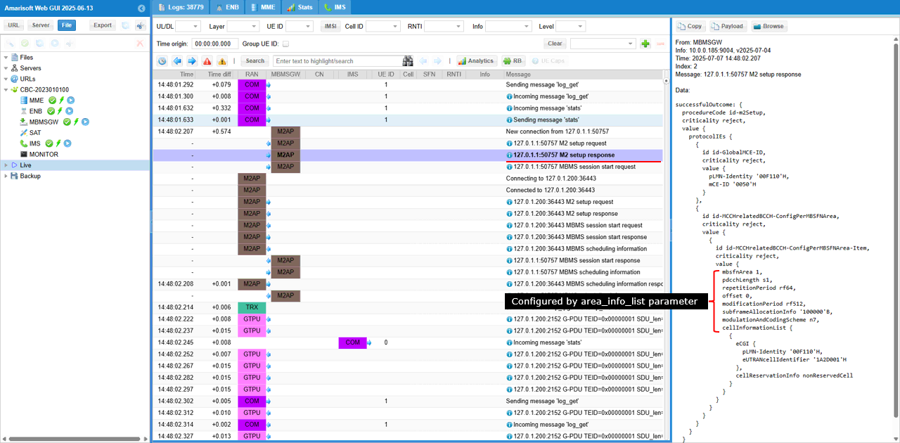
- area_info_list for transmission area configuration, including area_id, non_mbsfn_region_length, and mcch_config (with repetition period, offset, modification period, subframe allocation, and signaling MCS).
- mbsfn_area_configuration for MBSFN area settings, defining common_sf_alloc (radio frame period, offset, subframe allocation), pmch_info_list (PMCH allocation count, data MCS, scheduling period), and mbms_session_info_list (TMGI, logical channel identity).
- Configuration involves several key parameters and blocks:
- Test 1: Broadcasting from eNB with NO UE Connection
- This test validates MBMS broadcast at the network level, without requiring a UE to be connected.
- Procedure:
- Use provided configuration files (enb-mbms.cfg for eNB, mbmsgw.cfg for MBMS gateway).
- Apply standard eNB settings (frequency, cell ID, etc.), with special focus on the mbms block for synchronization and service area IDs, SIB13 periodicity, and notification configuration.
- Configure MBMS gateway with service definitions:
- Define broadcast services by PLMN and service ID, each assigned a service area, local GTP address and TEID.
- For each service, simulate multicast streams (video and audio) with specified IP/port and bitrate, using the simulation flag.
- Set scheduling period for periodic broadcast intervals.
- Configure area_info_list with area ID, control channel parameters, and subframe allocation for MCCH.
- Setup mbsfn_area_configuration for radio frame allocation and PMCH scheduling, ensuring subframe allocation and data MCS settings are consistent across configurations.
- Specify MBMS sessions (TMGI, service ID, logical channel identity) in each PMCH.
- Test Execution:
- Start LTE service on the callbox and use the cell command to verify configuration.
- Navigate to the MBMSGW monitoring screen to observe initialization and runtime status.
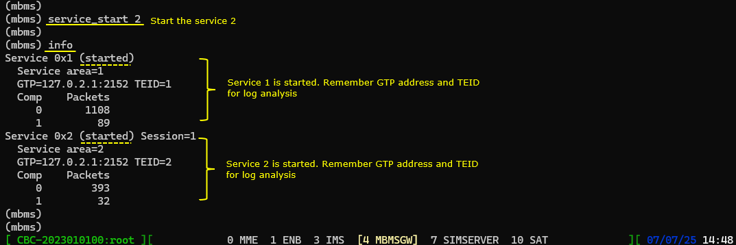
- Run info command in MBMSGW to list configured services, their status (started/stopped), and core parameters (service area, GTP IP/port, TEID).
- Start additional services as needed (e.g., service_start 2 to start the second broadcast service).
- Verification and Log Analysis:
- Monitor network-side logs and MBMSGW output for MBMS setup, session start, and scheduling information exchanges between eNB and MBMS gateway.
- Verify the following in logs and monitoring screens:
- Successful M2AP interface setup and configuration of MBMS service areas.
- Session start confirmation and correct GTP tunnel usage for each service.
- MCCH and PMCH scheduling in line with configuration (subframe allocation, repetition period, MCS, etc.).
- Traffic distribution across configured services, identified by TEID values in GTPU packets.
- PMCH transmission occurring at the expected subframe (e.g., subframe 1) as per configuration.
- Visualization of PMCH transmissions in RB Map plots and spectrum analyzer output, confirming broadcast activity in the expected resource blocks and subframes.
- Optional Spectrum Analysis:
- If available, use an extra SDR card as a spectrum analyzer to monitor MBMS broadcast transmissions in real time, following the referenced spectrum analyzer tutorial for setup.
This procedure provides a complete methodology for configuring, running, and validating MBMS broadcast at the network layer without involving UE registration, focusing on network-side parameterization, service definition, monitoring, and broadcast verification through logs and spectrum analysis tools.
Test Setup
Test setup for this tutorial is as shown below. This is just for low layer testing, you may not need any complicated IP layer setup.
- SIM Card used in this tutorial is the one delivered with the system as it is.
- If you want to change the configuration, The tutorial Configuration Guide would help
If you have a commercial UE that support UE assistance information with Release Preference, you can use the Setup A. If you don't have any commercial UE supporting this feature but have Amarisoft UEsim you can use Setup B. In this Test, Setup B is used.
Setup A
This is the setup for the case where you use a commercial phone as DUT.

Setup B
This is the setup for the case where you use Amarisoft UEsim as DUT.

Key Configuration Parameters
Followings are important configuration parameters for this tutorial. You may click on the items for the descriptions from Amarisoft documents.
- mbms
- services
- tmgi
- service_area_id
- session_id
- gtp_addr
- gtp_teid
- autostart
- scheduling_period
- time_offset
- forward_mode
- tos
- traffic_class
- ttl
- components
- area_info_list
Test 1 : Broadcasting from eNB with NO UE Connection
This test show the simplest way of testing MBMS which does not even require any UE connection. Since MBMS is broadcasting technology, it does not require any dedicated connection to a specific UE. In this test, I will go through the basic configuration for MBMS on network side and show how to verify the transmission of broadcast data on network side only. .
Configuration
I have used enb-mbms.cfg which is provided with installation package

I am using mbmsgw.cfg which are provided by the installation package..

enb-mbms.cfg is configured as follows.
Setting up basic configuration (e.g, frequency, cell id etc) are same as regular configuration.
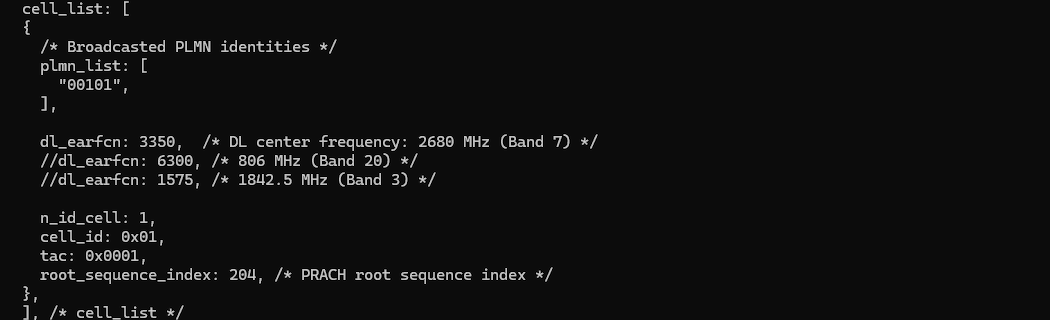
The special configuration on eNB is mbms block which specifies synchronization_area_id, service_area_id_list, sib13 periodicity and notification_config etc.
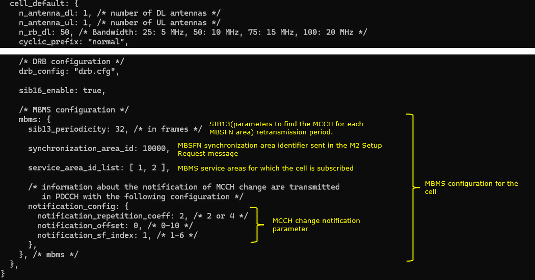
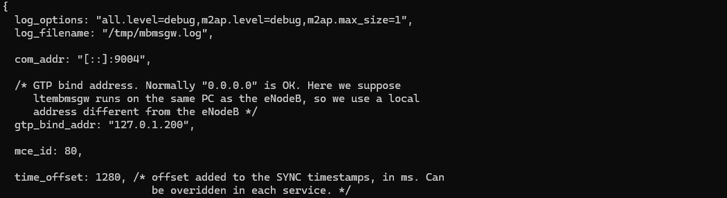
mbmsgw.cfg carries most of service related configuration and specifies some physical layer configurations for MBMS.
I used the mbmsgw.cfg which comes with installation package almost with no change. The onlything that I changed is log_options. I set all.level=debug to collect the detailed log.
This MBMS configuration defines two broadcast services in this test.
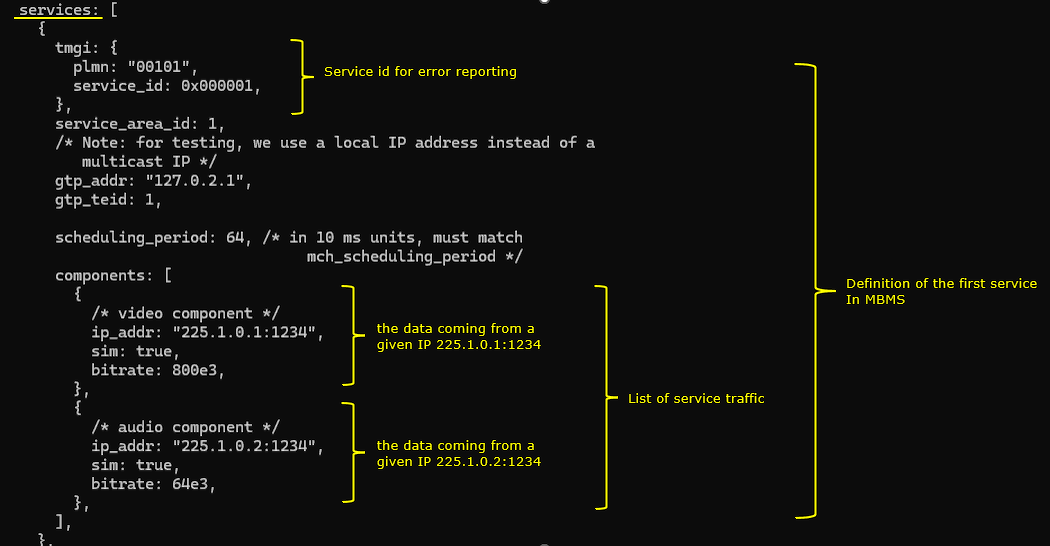
Following is the configurations for the first service. It is identified by the PLMN (plmn: "00101") and service ID (service_id: 0x000001). It operates in service area 1 (service_area_id: 1) and uses a local IP address (gtp_addr: "127.0.2.1") and GTP tunnel identifier (gtp_teid: 1) . The service broadcasts two simulated multicast streams defined under components: a video stream from IP and port 225.1.0.1:1234 with a bitrate of 800 kbps (bitrate: 800e3), and an audio stream from 225.1.0.2:1234 at 64 kbps (bitrate: 64e3), both with simulation enabled (sim: true). The scheduling interval for broadcasting is set to 640 ms (scheduling_period: 64)
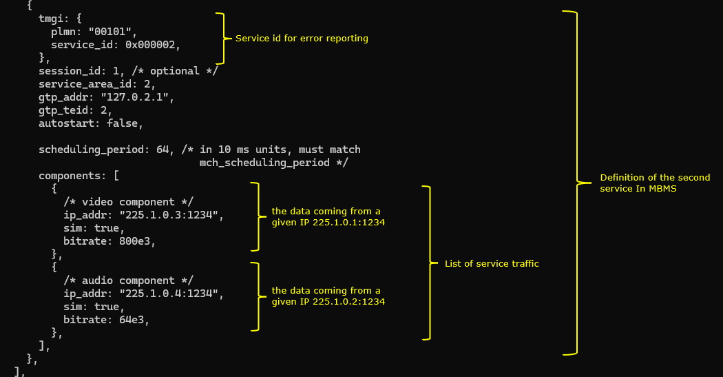
Following is the configurations for the second service. It is identified by the PLMN (plmn: "00101") and service ID (service_id: 0x000002). It operates in service area 2 (service_area_id: 1) and uses a local IP address (gtp_addr: "127.0.2.1") and GTP tunnel identifier (gtp_teid: 2). The service broadcasts two simulated multicast streams defined under components: a video stream from IP and port 225.1.0.1:1234 with a bitrate of 800 kbps (bitrate: 800e3), and an audio stream from 225.1.0.2:1234 at 64 kbps (bitrate: 64e3), both with simulation enabled (sim: true). The scheduling interval for broadcasting is set to 640 ms (scheduling_period: 64)
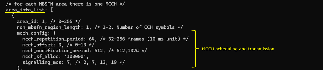
Following configuration defines the MBMS transmission area with area ID (area_id: 1) and sets the number of CCH symbols to 1 (non_mbsfn_region_length: 1). The mcch_config block specifies the control channel parameters for this area. The MCCH repetition period is set to 64 (mcch_repetition_period: 64), meaning MCCH messages are repeated every 640 ms. The offset for MCCH transmission is 0 (mcch_offset: 0), indicating no delay from the period start. MCCH modification information is updated every 5120 ms (mcch_modification_period: 512). The subframe allocation is defined by the bitmap (mcch_sf_alloc: '100000'), where only subframe 1 is used for MCCH. The modulation and MCS for signaling is set to 7 (signalling_mcs: 7)
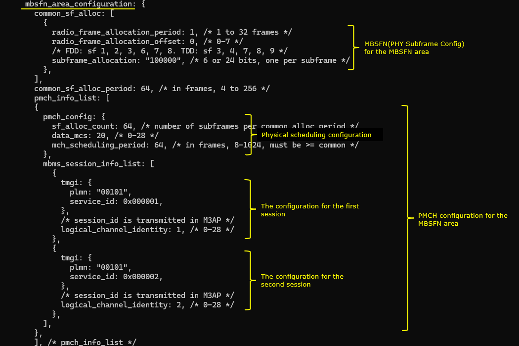
Following configuration defines the MBSFN area settings used for MBMS transmission. Under common_sf_alloc, it sets the radio frame allocation period (radio_frame_allocation_period: 1) and offset (radio_frame_allocation_offset: 0), along with the subframe bitmap (subframe_allocation: "100000"), which enables transmission in subframe 1 only.
The overall allocation cycle is specified by common_sf_alloc_period: 64, meaning the subframe pattern repeats every 64 radio frames (640 ms). The pmch_info_list block contains configuration for the PMCH. The pmch_config sets the number of subframes used per allocation cycle (sf_alloc_count: 64), the MCS for data transmission (data_mcs: 20), and the scheduling period for MCH (mch_scheduling_period: 64), which should match or exceed the common period.
Inside mbms_session_info_list, two separate MBMS sessions are configured. The first session is identified by PLMN "00101" and service ID 0x000001 (tmgi: { plmn: "00101", service_id: 0x000001 }) with logical channel identity 1 (logical_channel_identity: 1). The second session similarly uses the same PLMN with a different service ID 0x000002 and logical channel identity 2.
Perform the Test
Run lte service on callbox and check 'cell' command an see if everything is configured as intended.
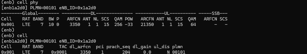
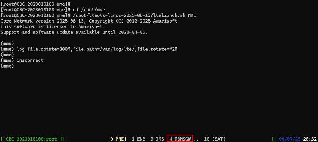
Check if you see the components MBMSGW shows up at the bottom of the screen.
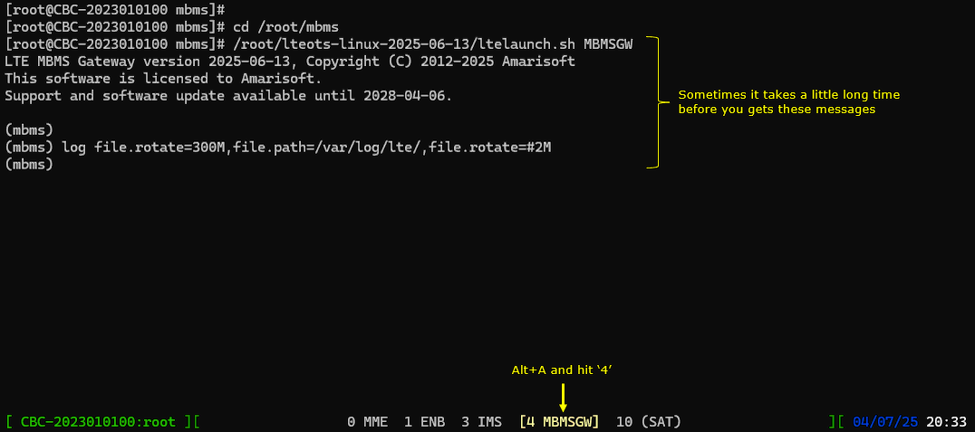
Go into MBMSGW screen and see if you get the initialization print out for MBMSGW.
The first thing you may try is to run info conmmand. It shows the list of all the configured services, status (start or stop) of each services and basic informations (e.g, Service Area, GTP ip:port, TEID) for each service.
By default, the first service gets started automatically and the remaining service is in stop state.
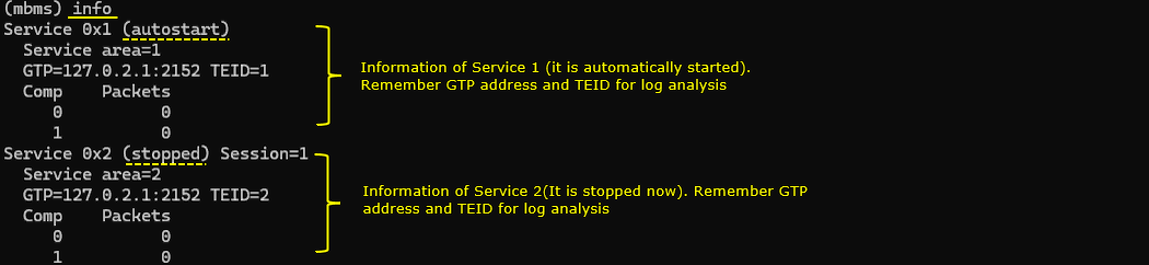
Now let's start the second service as well by running the command service_start 2.
Log Analysis
Following is the log snapshot that are involved in UE assistance information message and handling process.
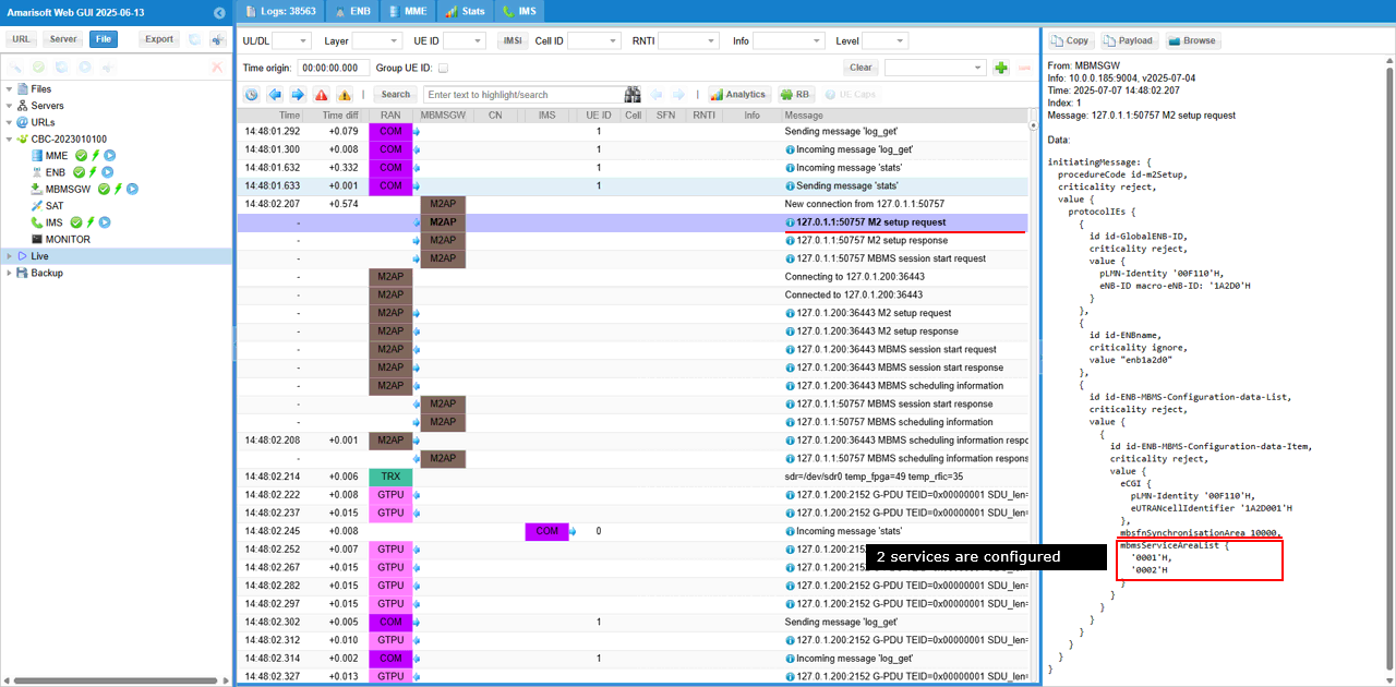
M2 setup request message sent over the M2AP interface. This message contains the mbmsServiceAreaList field, which indicates that two MBMS services (0001H and 0002H) are configured for delivery in this synchronization area.
M2 setup response confirms successful configuration of the MBMS control channel (MCCH) for the specified MBSFN area (mbsfnArea: 1). The parameters being delivered�such as repetitionPeriod: r64, offset: 0, modificationPeriod: r512, subframeAllocationInfo: '100000'B, and modulationAndCodingScheme: n7�are derived from the area_info_list configuration in the MBMS setup.
MBMS Session Start Request indicates the initiation of an MBMS service. It identifies the MBMS service using the Temporary Mobile Group Identity (plmnIdentity: '00101'H, serviceID: '000001'H) and specifies the MBMS service area ('000001'H). It also provides transport-level information using the TNL-Information field, which contains the IP multicast address (IPMulticastAddress: 'F7000201'H), IP source address (IPSourceAddress: '7F000181'H corresponding to 127.0.0.1), and the associated GTP tunnel endpoint (GTP-TEID: '00000001'H).
MBMS session start response message confirms successful activation of the MBMS session. The successfulOutcome structure indicates that the procedure for id-sessionStart was completed without error

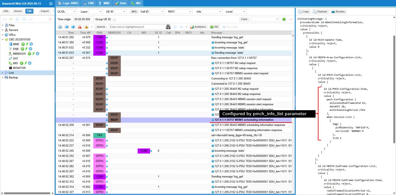
MBMS Scheduling Information message sent and it configures the physical layer scheduling parameters for MBMS delivery. It defines how the Physical Multicast Channel (PMCH) will be allocated. It includes the pmch-Configuration block specifying that 63 subframes are allocated for MBMS (allocatedSubframesEnd: 63), the MCS for transmission (dataMCS: 20), and the scheduling period (mchSchedulingPeriod: r64, or 640 ms). Additionally, the message lists the active MBMS session (mbms-Session-List), identified by its plmnIdentity: '00101'H and serviceID: '000001'H, with lcid: 1
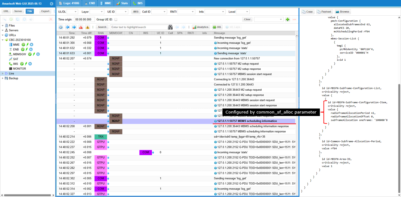
This is another set of configuration to be noted in MBMS scheduling Information. The set of IE(information elements) under id-MBSFN-Subframe-Configuration-Item confirms the configuration of the MBSFN subframe usage for the MBMS service. It specifies the subframe allocation timing using radioFrameAllocationPeriod: n1 and radioFrameAllocationOffset: 0, and provides the subframe usage pattern via the bitmap subframeAllocation oneFrame: '100000'B, which means only subframe 1 is allocated for MBMS transmission within each radio frame.
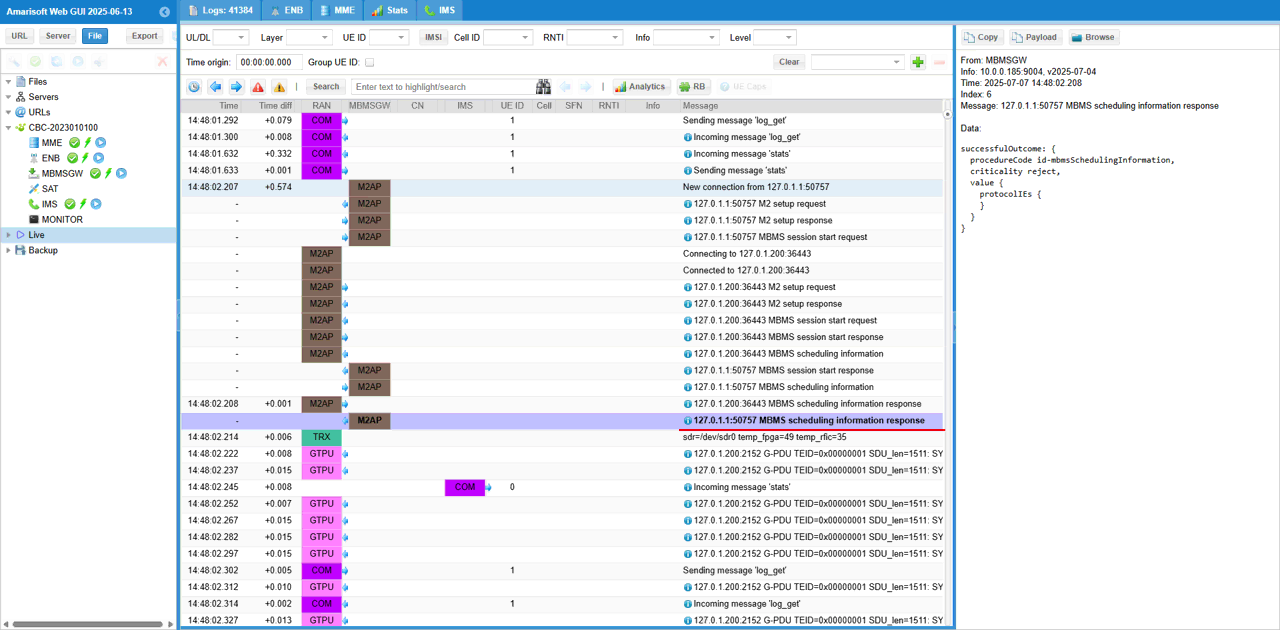
MBMS Scheduling Information Response confirms the successful reception and acceptance of the MBMS scheduling information previously sent
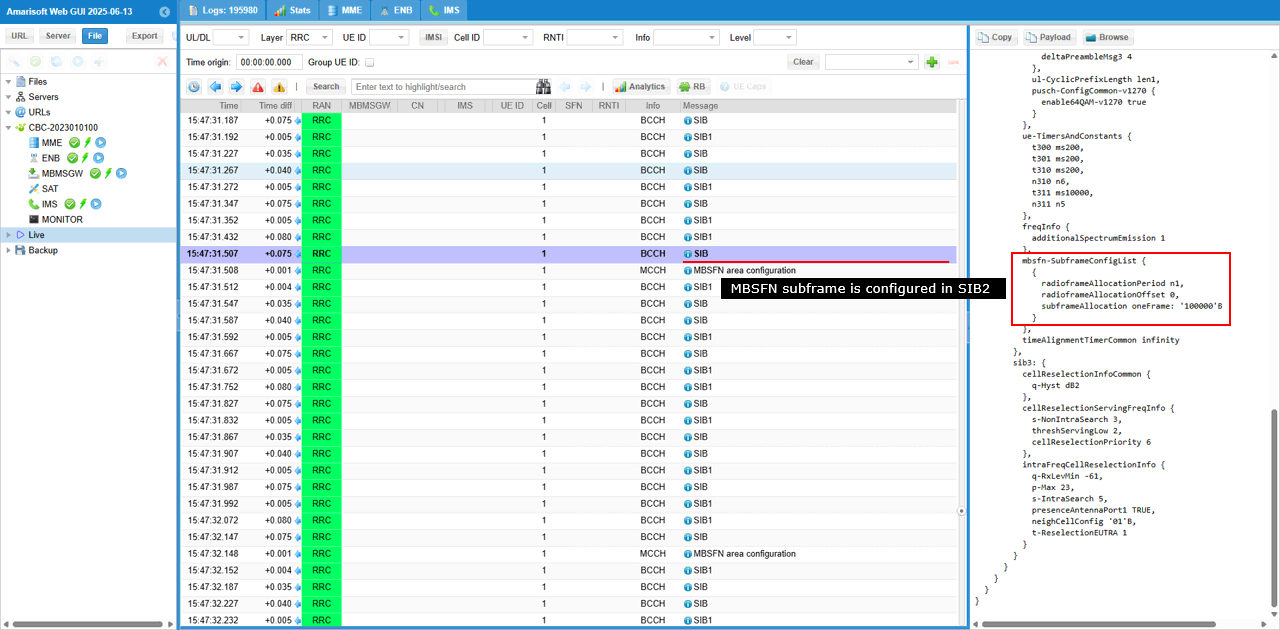
In SIB2, there is the IE mbsfn-SubframeConfigList that configures subframe configuration of MBMS (mbsfn). mbsfn-SubframeConfigList indicates the specific allocation of MBSFN subframes. It specifies that the radio frame allocation period is n1 (radioFrameAllocationPeriod n1), the offset is 0 (radioFrameAllocationOffset 0), and the subframe allocation bitmap is '100000'B, which means only subframe 1 in each radio frame is reserved for MBSFN transmission.
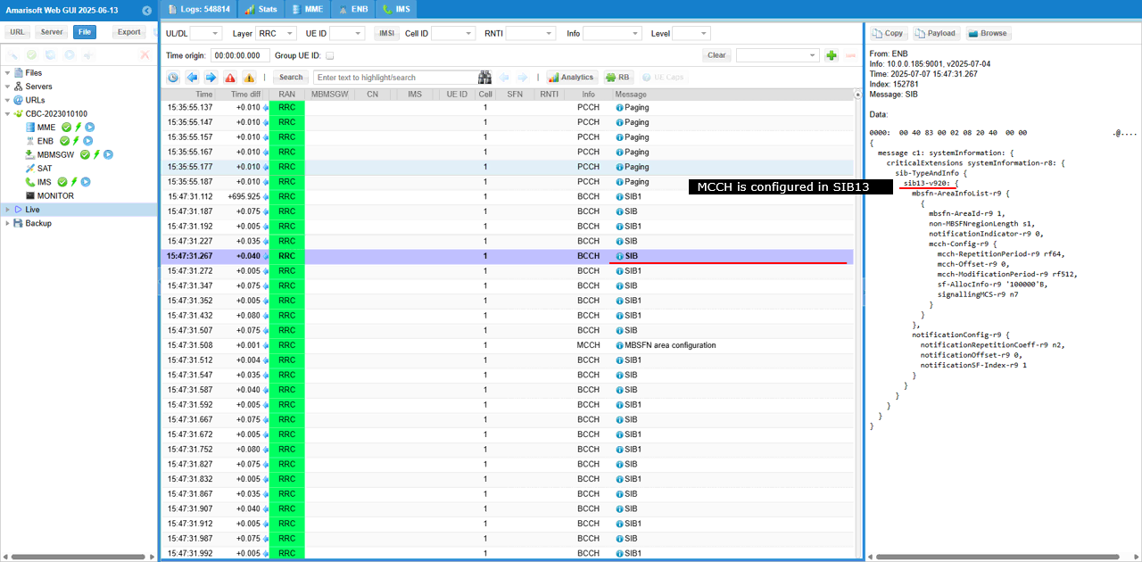
The mbsfn-AreaInfoList within sib13 specifies key MCCH parameters derived from the area_info_list configuration. It includes the area ID (mbsfn-AreaId: 1), the number of non-MBSFN symbols (non-MBSFNregionLength: 1), and the detailed mcch-Config such as: mcch-RepetitionPeriod, mcch-Offset, mcch-ModificationPeriod, sf-AllocInfo, signallingMCS
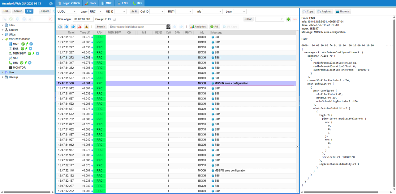
MBSFN area configuration message sent over the MCCH,. It informs UEs how MBMS transmissions are scheduled. It includes the subframe allocation pattern (commonSF-Alloc-r9), specifying that subframe 1 is used (subframeAllocation oneFrame: '100000'B) every radio frame (with radioFrameAllocationPeriod: n1 and radioFrameAllocationOffset: 0), and that the allocation repeats every 640 ms (commonSF-AllocPeriod-r9: r64). The PMCH section (pmch-InfoList-r9) defines that 63 subframes are used for data transmission (sf-AllocEnd-r9: 63) with MCS index 20 (dataMCS-r9: 20) and a scheduling period of 640 ms (mch-SchedulingPeriod-r9: r64). Additionally, it announces the active MBMS session (mbms-SessionInfoList-r9) with PLMN ID 001-01 (plmn-Id-r9), service ID 0x000001 (serviceId-r9) and logical channel identity 1 (logicalChannelIdentity-r9)
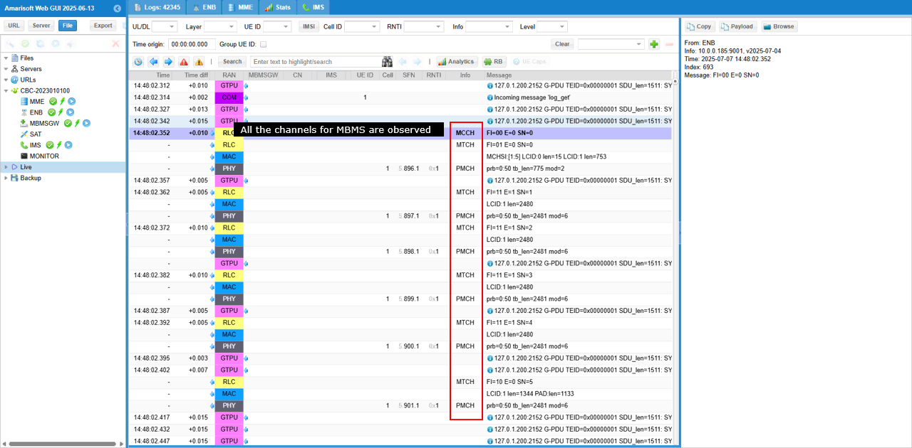
Once all the configurations are properfly configured as described above, you would see the traffics for all the channels from MCCH through PMCH
You would remember two broadcase services are configured for this test. You can identify traffics for a specific services by TEID field in GTPU packet.
At the beginning of this test, you would see GTPU packets with only TEID = 1 since only service 1 is started at the beginning.
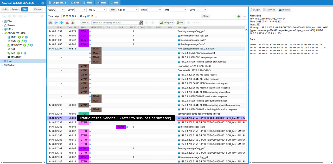
After you start server 2, you would start seeing the GTPU packets with TEID = 2 as well.
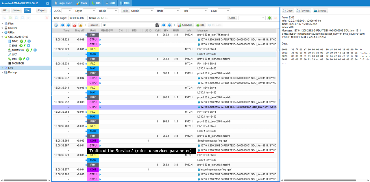
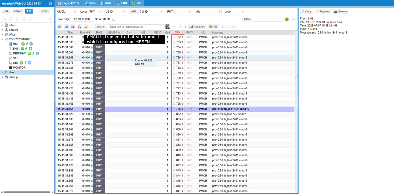
You would notice that All PMCH is transmitted at subframe 1 as confitured.
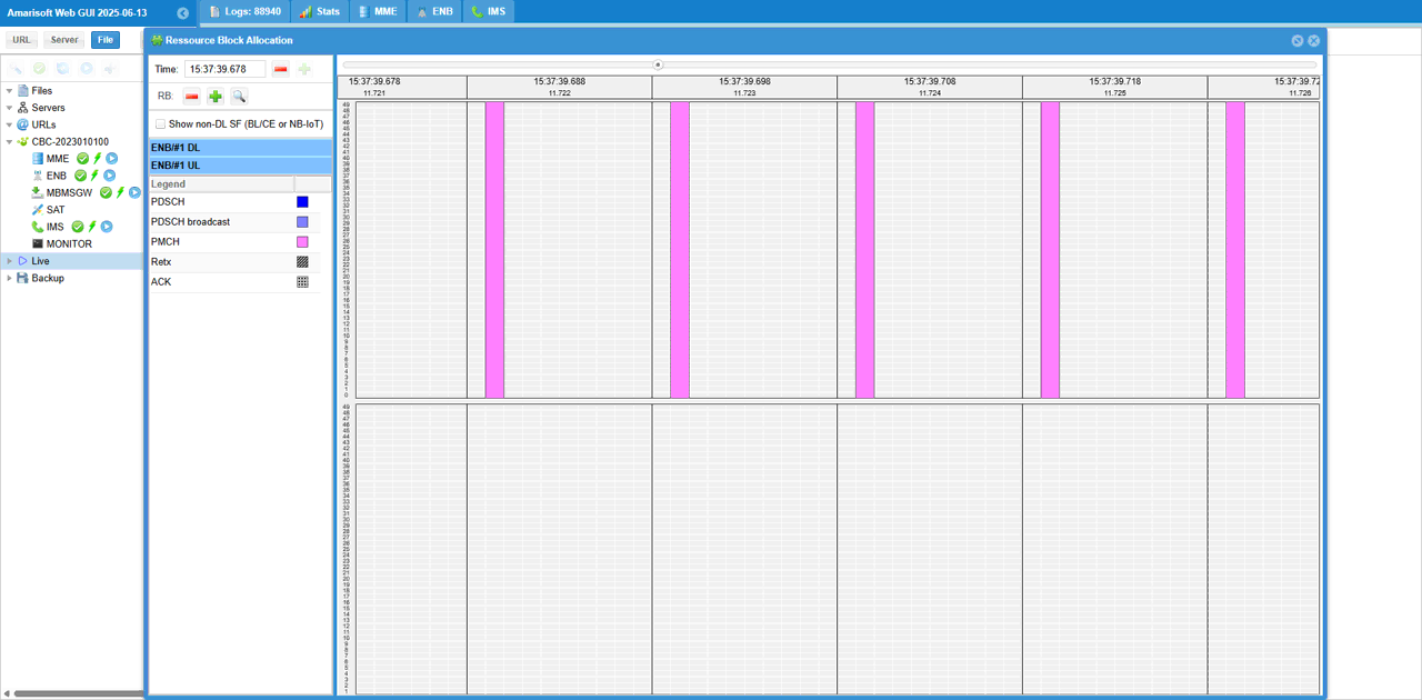
You can check out the PMCH transmission visually in RB Map plot, showing all the PMCH at subframe 1.
If you have any extra sdr card (e.g, a callbox with multiple SDR cards or UEsim), you can use it as spectrum analyzer and check out PBCH transmission in real time (
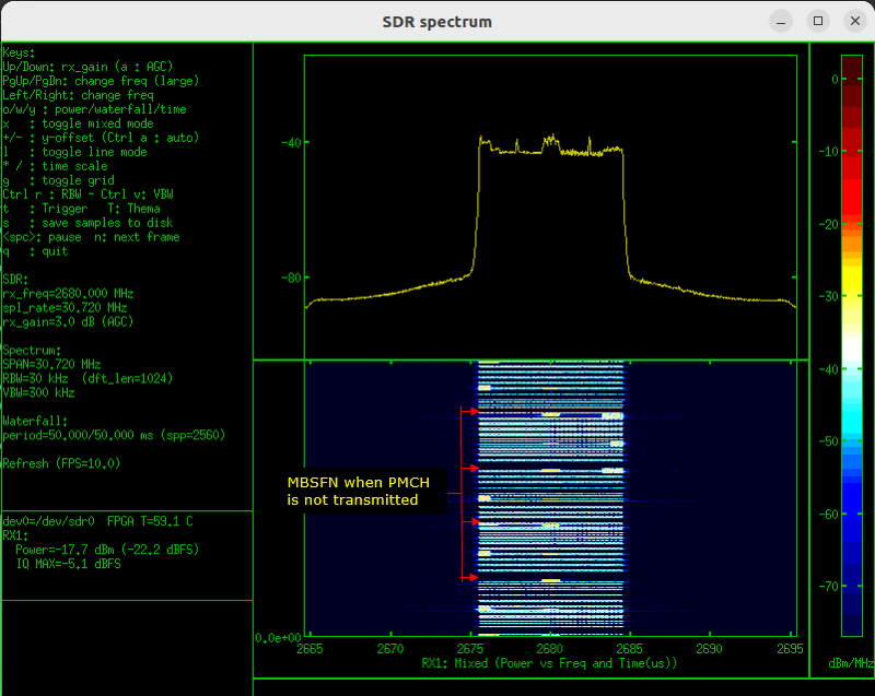
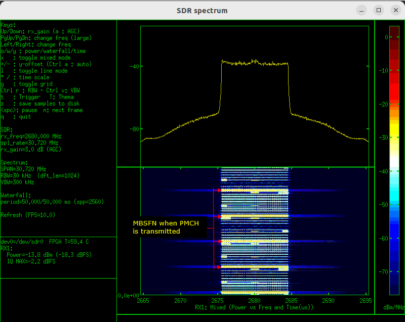
Following is the spectrum analyzer captured as animation.