LTE LPP (LTE Positioning Protocol)
This tutorial is to show how to configure and test LPP. LPP stands for LTE Positioning Protocol and it is a mechanism to facilitate the exchange of positioning information between the mobile device and the network. Conceptually in terms of the purpose LPP is similar to SUPL(Secure User Plane Location). Main differences from SUPL would be
- LPP can be associated not only with GPS but also with other system like GLONASS, Galileo, and QZSS etc whereas SUPL is mainly associated with GPS
- LPP support the information exchange not only via U-plane but also via C-Plane whereas SUPL supports U-Plane only.
- LPP is supported in LTE and NR, whereas SUPL is supported in 3G/4G.

- Only C-Plane LPP is supported (U-Plane LPP is not supported)
- LCS Server (SLP, E-SMLC) is not supported by Amarisoft. Instead we provide a feature to generate location request and process the response by internal test function. (
NOTE : If you have your own LCS server, it can be connected to Amarisoft LPP functionality)
Table of Contents
- LTE LPP (LTE Positioning Protocol)
Introduction
The LTE Positioning Protocol (LPP) is a standardized mechanism designed to enable accurate location determination in advanced mobile networks, including LTE and 5G NR. Functioning as a control-plane protocol, LPP facilitates the exchange of positioning information between User Equipment (UE) and the network's location services infrastructure, such as the Evolved Serving Mobile Location Center (E-SMLC) or Secure Location Platform (SLP). Unlike legacy protocols like SUPL (Secure User Plane Location), which primarily rely on user-plane signaling and are focused on GPS, LPP is architected to support a diverse array of Global Navigation Satellite Systems (GNSS) including GPS, GLONASS, Galileo, and QZSS. LPP's architecture enables both control-plane and user-plane operation modes, though implementation support may vary between platforms. Its modular message structure allows the protocol to carry assistance data, measurement reporting, and location information efficiently and securely. LPP plays a pivotal role in enabling location-based services (LBS) and regulatory features such as emergency call positioning, and it is integral to modern mobile ecosystems where accurate and reliable location data is mission-critical. As mobile networks evolve to support higher positioning accuracy and expanded GNSS capabilities, LPP’s flexible framework ensures extensibility and interoperability across different radio access technologies and network deployments.
-
Context and Scope
- LPP is a 3GPP-defined protocol supporting advanced location-based services in LTE and 5G NR networks.
- It operates primarily in the control plane, enabling robust and secure information exchange between mobile devices and network-side location services servers.
- This tutorial focuses on the configuration and testing of LPP, specifically within the Amarisoft software environment, highlighting protocol features, limitations, and real-world application scenarios.
-
Relevance and Importance
- LPP enhances the accuracy, reliability, and flexibility of positioning in mobile networks, supporting regulatory requirements and commercial LBS applications.
- The protocol’s support for multiple GNSS systems and dual-plane operation (control and user plane) makes it essential for operators and developers targeting next-generation mobile services.
- Understanding LPP is critical for engineers working on network deployment, device integration, and service development where location is a key differentiator.
-
Learning Outcomes
- Gain a solid understanding of LPP’s role and operation within LTE and 5G environments.
- Learn how to configure and test LPP features using Amarisoft’s platform, including generating and processing location requests.
- Identify current limitations in LPP implementations and understand integration points for external LCS servers.
- Develop the ability to troubleshoot and extend positioning solutions for advanced mobile networks.
-
Prerequisite Knowledge
- Familiarity with LTE/5G network architecture and components (e.g., eNodeB, gNodeB, EPC, 5GC)
- Basic understanding of mobile positioning concepts and GNSS technologies
- Experience with network protocol configuration and test procedures
- Exposure to Amarisoft or similar mobile network testing environments is beneficial but not mandatory
Summary of the Tutorial
This tutorial covers procedures for testing LTE LPP (LTE Positioning Protocol) ECID (Enhanced Cell-ID) positioning using both auto and manual configuration methods. The tests are designed for setups using either a commercial UE or Amarisoft UEsim as the Device Under Test (DUT). Two main test scenarios are described: Auto Configuration - ECID and Manual Configuration. The overall methodology includes configuration steps, test execution, and log analysis to validate LPP-based positioning functionality.
-
Test Setup
- Two test setups are provided:
- Setup A: Using a commercial UE as DUT.
- Setup B: Using Amarisoft UEsim as DUT.
- SIM card provided with the system is used for all tests.
- Configuration changes can be referenced from the Configuration Guide if needed.
- Two test setups are provided:
-
Key Configuration Parameters
- Critical parameters include nl1, lcs, and local_e_smlc blocks in the configuration files.
- Parameters such as api_root, transaction_timeout, server_bind_addr, and others under each block are highlighted as important for LPP/LCS functionality.
- Assistance data for OTDOA and NR-TDOA are referenced, though not detailed exhaustively in the steps.
-
Test 1: Auto Configuration - ECID
- Objective: Demonstrate LPP in LTE with minimal manual configuration�most parameters are auto-configured by the LTE stack.
-
Configuration Steps:
- Use default configuration files (enb.default-lpp.cfg for eNB/gNB, mme-ims-lte-lpp-auto.cfg for MME, ue-lpp.cfg for UEsim) with minimal or no modification.
- Ensure FDD mode and 5MHz bandwidth are set; dl_earfcn matches the desired LTE band (e.g., Band 7).
- In MME configuration, enable autonomous_mode: true in local_e_smlc block; set basic identity parameters (e.g., plmn, enb_id).
- On UEsim, ground position origin must be configured for GNSS responses; otherwise, GNSS report requests will result in errors.
-
Test Execution:
- Verify cell configurations using cell phy and cell commands.
- On the MME, check LCS connection status with the lcs command (should be state=connected).
- Power on the UE (UEsim).
- Ensure initial attach completes successfully.
- Trigger a location request via Remote API:
-
Log Analysis:
- Confirm successful LCSAP connection before triggering LPP measurement.
- Trace the end-to-end procedure: Location request, LPP capability exchange, measurement configuration, reporting, and final location estimate.
- Key aspects include validation of capability negotiation, measurement initiation, and location result reporting.
General Methodology Notes:
- Both tests emphasize the need for matching cell parameters (e.g., dl_earfcn, bandwidth) across eNB/gNB and UEsim for successful signaling and measurement exchange.
- Manual configuration allows for explicit control of positioning method selection, reporting intervals, and assistance data, beneficial for debugging or deterministic testing.
- Remote API commands are used for triggering location procedures and requesting measurement reports; responses should be monitored for completeness and correctness within the allowed session timeframes.
- Log analysis is essential for verifying the step-by-step signaling, ensuring that each phase of LPP/ECID positioning (from attach to final location reporting) is executed as expected.
Test Setup
Test setup for this tutorial is as shown below.
- SIM Card used in this tutorial is the one delivered with the system as it is.
- If you want to change the configuration, The tutorial Configuration Guide would help
Setup A
This is the setup where you use a commercial UE as DUT.

Setup B
This is the setup where you use a commercial Amarisoft UEsim as DUT.

Key Configuration Parameters
Followings are important configuration parameters for this tutorial. You may click on the items for the descriptions from Amarisoft documents.
Test 1 : Auto Configuration - ECID
This is to show how to configure and verify LPP in LTE with auto configuration, where you set very minimal configuration and all the other details are automatically configured by lte software. The goal is to keep the setup as small as possible. You only set the few mandatory parameters to enable positioning. Then the LTE stack automatically fills in the remaining details. This feature is supported only by recent release (Feb 2026 or later is recommended).
Configuration
I have used enb.default-lpp.cfg on Callbox (gNB) as it is without any modification.

I am using the mme-ims-lte-lpp-auto.cfg which is copied and modified from mme-ims.cfg

I have used enb.default-lpp.cfg on UEsim as it is without any modification.

For eNB configuration, enb.default-lpp.cfg is configured as follows.
In this example, the cell is configured as an LTE FDD cell.
The downlink bandwidth is set to 5 MHz by setting N_RB_DL to 25. This means the LTE carrier uses 25 resource blocks in downlink.
The antenna configuration is kept simple. The downlink antenna is set to 2, which means 2x2 MIMO is used. The uplink antenna is also set to 2.
The channel simulator is disabled by setting CHANNEL_SIM to 0. This means the test uses the normal RF or simulated connection without adding an additional channel model inside the eNB configuration.
NG_ENB is set to 0, so this configuration is for normal LTE eNB operation, not ng-eNB operation.

Specify dl_earfcn according to the LTE band and frequency that you want to use.
In this test, LTE Band 7 is used. So dl_earfcn is set to 350.
This value corresponds to a downlink center frequency of 2680 MHz in Band 7.
The configuration file includes several example EARFCN values for different LTE bands. Most of them are commented out. Only the line for Band 7 is enabled in this example.
The PLMN is configured as 00101. This is the test PLMN used by the eNB. The UE configuration should use the same PLMN so that the UE can select and attach to this LTE cell.
Since NG_ENB is set to 0 in the previous part, the normal LTE PLMN configuration is used. The 5GC-related PLMN configuration under NG_ENB is not used in this test.

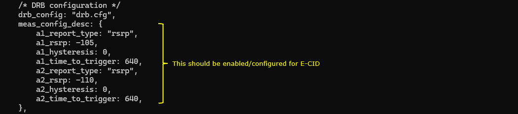
For ECID measurement, the LTE measurement configuration should be enabled.
In this example, meas_config_desc is configured in the eNB configuration file.
This part defines how the UE reports radio measurement results to the eNB.
The first report configuration uses RSRP as the trigger type. The threshold is set by a1_rsrp. When the serving cell quality becomes better than this threshold, the UE can send an A1 measurement report.
The second report configuration also uses RSRP. The threshold is set by a2_rsrp. When the serving cell quality becomes worse than this threshold, the UE can send an A2 measurement report.
For ECID positioning, these measurement reports are important because ECID is based on radio-related information such as serving cell identity, received signal strength, and timing-related information.
So this measurement configuration should be enabled when testing ECID-based LPP positioning.
In mme-ims-lte-lpp-auto.cfg , the e-SMLC configuration is specified. It is configured by the parameter local_e_smlc. In this test, the auto configuration is used that requires the minimum set of configuration. You define how the built-in e-SMLC behaves through the local_e_smlc block. The key point of this test is that you enable auto configuration, so you only provide the minimum identity information that the LTE stack needs, and then the software derives the rest of the LPP/LCS behavior automatically. autonomous_mode: true is the switch that tells the Amarisoft stack to run the e-SMLC logic with auto-generated defaults. The enb sub-block gives the identity that must be consistent with your LTE network, such as plmn: "00101", enb_type: "macro", and enb_id: 0x1A2D0

In ue-lpp.cfg , no special LPP-specific parameter is configured in this test.
The default LTE configuration on UEsim is used as it is.
The UE is configured for LTE FDD by setting TDD to 0.
The UE bandwidth is set to 5 MHz by setting CELL_BANDWIDTH to 5. This should match the eNB configuration, where N_RB_DL is set to 25.
The antenna configuration is kept simple. N_ANTENNA_DL is set to 1 and N_ANTENNA_UL is set to 1, so the UE uses a single antenna for downlink and uplink.
UE_COUNT is set to 1. This means only one simulated UE is created for this test.
CHANNEL_SIM is set to 0, so the UE-side channel simulator is disabled.
This keeps the UE configuration simple. The main purpose of this test is not to tune UE radio behavior, but to verify that LTE attach and LPP ECID positioning can work with the minimum required configuration.

In ue-lpp.cfg, ground_position_at_origin should be configured under cell_groups.
This parameter defines the reference ground position of the UE simulator.
In this example, latitude, longitude, and altitude are configured. This gives UEsim a known simulated position.
This configuration is required when the UE needs to respond to an LPP location request involving GNSS-type positioning information.
If this parameter is not configured, UEsim may not have a valid position source to use for the GNSS report. In that case, when the network requests GNSS positioning information through LPP, UEsim may send an error message in NAS instead of sending a valid LPP location information response.
So even though this test is mainly for ECID, it is safer to configure ground_position_at_origin in the UE simulator configuration. This gives the UE simulator a basic location reference and prevents failure when the LPP procedure includes a GNSS-related request.

The UE cell frequency should be configured to match the eNB cell frequency.
In this test, the eNB is configured for LTE Band 7. So the UE is also configured with the same dl_earfcn value.
Here, dl_earfcn is set to 3350.
This corresponds to the downlink center frequency of 2680 MHz in Band 7.
This value is important because UEsim searches for the LTE cell based on this frequency. If the UE and eNB use different dl_earfcn values, the UE may not find the cell. As a result, the attach procedure will not start, and LPP positioning cannot be tested.
So the basic rule is simple.
The dl_earfcn in ue-lpp.cfg should be the same as the dl_earfcn in the eNB configuration.

The UE configuration in ue_list is also used as in the default configuration.
In this example, one UE profile is defined with IMSI and K value.
The IMSI is used by the EPC to identify the UE. The K value is the authentication key used during LTE authentication. These values should match the subscriber information configured on the core network side.
The UE capability is kept as default.
as_release is set to 13, so the simulated UE behaves as a Release 13 UE.
ue_category is also set to 13. This defines the LTE UE category used by UEsim.
ue_count is set to UE_COUNT. Since UE_COUNT was set to 1 earlier, only one UE is created from this UE profile.
No special LPP-specific UE capability is manually added here. The purpose of this test is to use the default UE profile and verify that LPP ECID positioning can work with the minimum UE-side configuration.

Perform the test
After completing the configuration, start the eNB and UEsim and check whether the cell is configured as intended. This is the first sanity check before starting the LTE-LPP positioning procedure. If the cell frequency, PLMN, bandwidth, or PCI is not configured correctly, the UE may fail to attach and the LPP test cannot proceed.
In this example, the cell phy command shows one LTE cell, Cell 0x001. The PLMN is 00101 and the eNB_ID is 0x1a2d0. The cell is configured as LTE Band 7 with 5 MHz bandwidth. The downlink ARFCN is 3350 and the uplink ARFCN is 21350. The downlink uses 2 antennas and the uplink also uses 2 antennas. The downlink SCS is 15 kHz and the uplink SCS is also 15 kHz. The downlink modulation is 256 QAM and the uplink modulation is 64 QAM. There is no SSB information because this is LTE, not NR.
The cell command shows the logical cell configuration. Cell 0x001 is an LTE cell in Band 7. The TAC is 0x0001, dl_earfcn is 3350, and PCI is 1. The PRACH sequence index is 204, downlink gain is 0.0, UL disabled is N, and PLMN is 00101.
This confirms that the running eNB configuration matches the intended LTE Band 7 setup. Once this basic cell configuration is confirmed, you can continue to UE attach verification and then trigger the LTE-LPP location request.

Next, switch to the MME screen and run the lcs command. This command is used to check the LCS connection state. Before sending the LPP location request, make sure that the LCS connection is already established.
In this example, the lcs command output shows the LCS connection state. The server is 127.0.1.100:9082, and the state is connected. This means the MME has a working connection to the LCS-related server process, and the positioning control path is ready.
This step is important because the UE attach alone is not enough for the positioning test. Even if the UE is attached successfully, the LPP procedure may not start correctly if the LCS connection is not connected. Once the LCS state is confirmed as connected, you can continue to the UE attach verification and then send the location request.

Power on a UE in UEsim
![]()
Next, make sure that the initial attach is completed properly. This should be checked before sending the LPP location request. The LPP procedure is performed after the UE is already connected, so the positioning test should not be started until the UE has successfully attached and normal radio activity is visible.
In this example, the trace is started from the eNB console by running the t command. The PRACH line shows cell=e01, seq=34, ta=3, and snr=29.0 dB. This indicates that the UE transmitted PRACH and the eNB detected it successfully with a valid timing advance and good signal quality.
After that, the trace shows UE activity for UE-ID 1 on Cell 001 with RNTI 003d. The downlink side shows CQI values such as 3 and 4, RI 1, MCS values around 1.5 to 6.5, and downlink bitrate values such as 84, 92, 100, 112, and 208. The downlink SNR values are shown around 19.9 to 27.9 dB. On the uplink side, the trace shows PUCCH SNR values around 31.6 to 32.3 dB, uplink MCS 0, uplink bitrate 0, PHR 40, pathloss 48, and timing advance close to 0.0.
This confirms that the UE has completed the initial access procedure and has an active LTE radio connection with RNTI 003d. Once this kind of UE activity is visible, you can continue to the LTE-LPP positioning request step.

On the Callbox, send the Remote API command to trigger the location request message toward the UE. Run this command from the root/mme directory on the Callbox. This step starts the LTE-LPP positioning procedure from the network side.
./ws.js mme '{"message": "location_req","imsi": "001010123456789","imei": "01234567000001","session_id": 1,"plmn": "00101","cell_id": 0x1A2D001,"type": "geographic"}'
In this example, the command is sent to mme using ws.js. The message is location_req. The target UE is identified by imsi set to 001010123456789 and imei set to 01234567000001. The session_id is set to 1. The PLMN is set to 00101, which matches the PLMN used in the LTE cell configuration. The cell_id is set to 0x1A2D001. The type is set to geographic, which means the requested location result is a geographic position.
The Remote API output shows that ws.js connects to 127.0.1.100:9000. It also shows Ready with name=MME, type=MME, and version=2026-02-06. Then the tool sends the location_req message with id#1 and receives a response from the MME.
The response contains message set to location_req and message_id set to 1. This means the MME accepted the Remote API command. At this point, the location request has been submitted successfully. The next step is to check the protocol log and confirm that the LPP message is delivered to the UE and that the UE sends the corresponding LPP response.
|
[root@CBC-2023010100 mme]# ./ws.js mme '{"message": "location_req","imsi": "001010123456789","imei": "01234567000001","session_id": 1,"plmn": "00101","cell_id": 0x1A2D001,"type": "geographic"}' WebSocket remote API tool version 2026-02-15, Copyright (C) 2012-2026 Amarisoft [0.003] ### Connected to 127.0.0.1:9000 [0.003] ### Ready: name=MME, type=MME, version=2026-02-06 [0.023] <== Send message location_req id#1 [0.044] ==> Message received { "message": "location_req", "message_id": "id#1", "time": 48.569, "utc": 1707145581.655 } |
Log Analysis
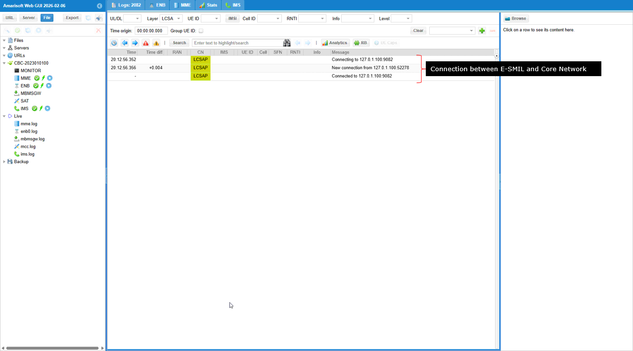
This log is shown before you trigger any LPP measurement, and it only confirms that the e-SMLC side is connected to the Core Network over LCSAP. In the LCSAP layer you see the connection setup toward the Core Network address, and then the Connected status, so it tells you the transport path for location services signaling is ready. At this stage there is no LPP transaction yet, no requestCapabilities, and no RequestLocationInformation, so you should treat this as a prerequisite connectivity check between the e-SMLC function and the MME/Core Network.
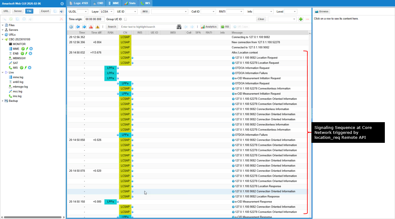
If you trigger LPP measurement by the remote API ./ws.js mme '{"message": "location_req","imsi": "001010123456789","imei": "01234567000001","session_id": 1,"plmn": "00101","cell_id": 0x1A2D001,"type": "geographic"}'. You will get a long sequence of transactions as shown below.
First, the Core Network allocates the location context and creates the LCSAP session toward the e-SMLC. Then the e-SMLC starts LPP capability exchange to learn whether the UE supports A-GNSS, OTDOA, and E-CID. The LPP payloads are tunneled through the MME and delivered to the UE via NAS generic NAS transport with the generic message container type=1. Based on the capability results and available assistance data, the network may attempt OTDOA, and if it fails or is not usable it proceeds with E-CID measurement initiation. The UE then reports measurements such as RSRP/RSRQ and Rx-Tx time difference, and the positioning side computes the estimate. Finally, you see the Location Response on LCSAP, which carries the completed coordinate estimate back to the requester, and the related transactions are acknowledged and closed.
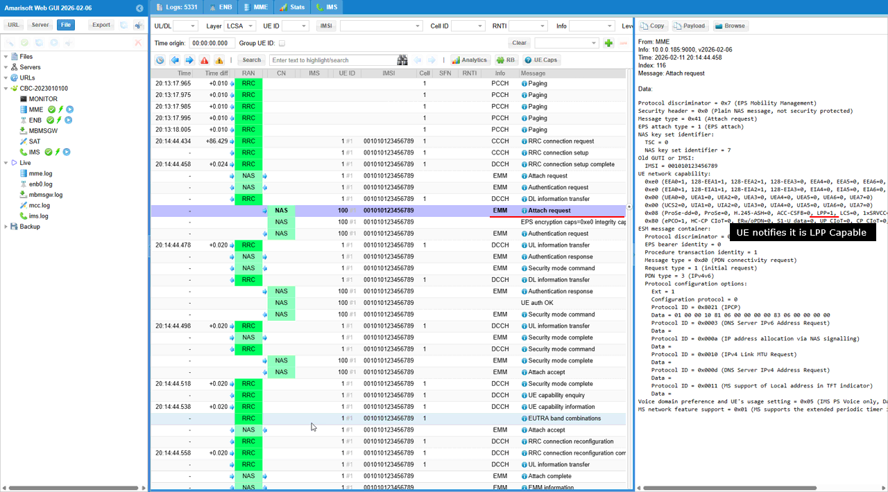
In this Attach request, the UE is advertising its positioning support through the UE network capability IE. In the hex-decoded capability line you can see LPP=1, which means the UE declares it supports LTE Positioning Protocol (LPP). This is an early I am LPP-capable indication to the MME, so the core network knows it is allowed to deliver LPP payloads later using Generic NAS transport with Generic message container type=1. This is not the detailed capability handshake yet. The detailed method-level profile (A-GNSS/OTDOA/E-CID modes, bands, coordinate types) is still learned later through the actual LPP requestCapabilities / provideCapabilities exchange.
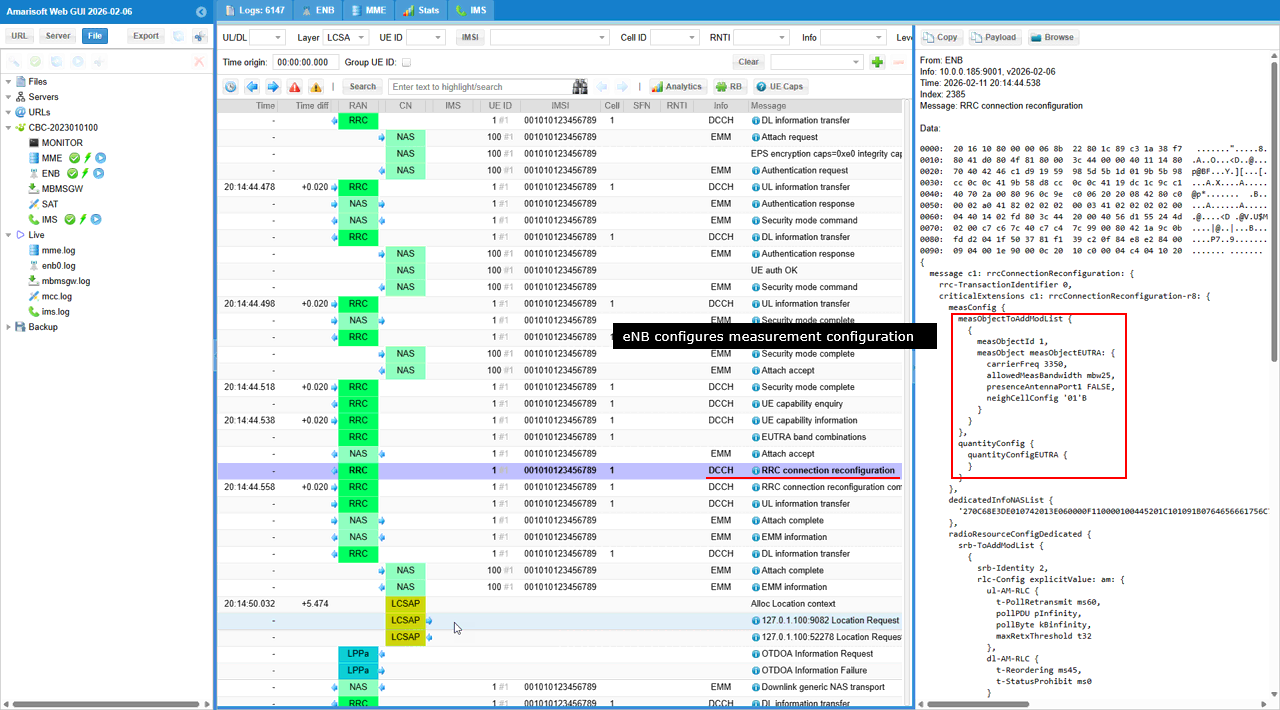
This RRCConnectionReconfiguration is where the eNB pushes the measurement configuration (measConfig) down to the UE, so the UE knows what to measure and how to report it. In the highlighted part you can see a measObject being created for E-UTRA with an ARFCN (earfcn 3350) and a neighbor-cell configuration, which tells the UE what carrier/cell context the measurements belong to. You also see a quantityConfig / quantityConfigEUTRA, which defines what measurement quantities are relevant for that object, so the UE can later produce results like RSRP/RSRQ (and, when enabled, timing-related items such as Rx-Tx time difference) in its MeasurementReport. The key point is that this message is the setup step that enables all the measurement reporting used later by the positioning flow, including the E-CID snapshot that gets copied into LPP provideLocationInformation.
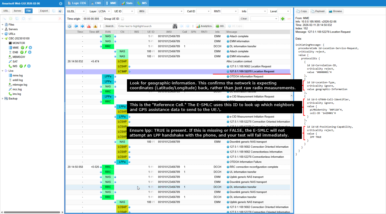
The message underlined in red is the LCS-AP Location Request. This is the "Command" message sent from the MME to the E-SMLC (Location Server) to initiate the positioning process for a specific UE. This message tells the E-SMLC why the location is needed and what kind of accuracy is required. It acts as the master trigger for all the LPPa and LPP sub-messages you see following it in the trace.
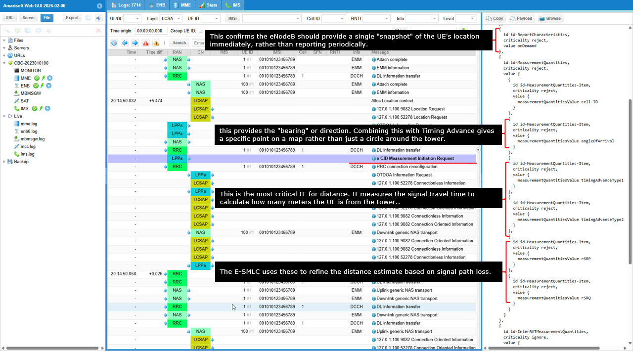
The message is the LPPa: e-CID Measurement Initiation Request. The e-CID (Enhanced Cell-ID) method is the network's secondary positioning strategy. While OTDOA (which failed earlier in your trace) relies on the UE measuring multiple base stations, e-CID asks the serving base station to report specific radio parameters it already knows about the UE. It is faster and more reliable in poor signal conditions, though generally less accurate than GPS or OTDOA.
timingAdvanceType1/timingAdvanceType2 gives the UE-to-eNodeB range estimate because it reflects the propagation delay. angleOfArrival (AoA) gives the bearing when the antenna supports it, so combining AoA with Timing Advance turns a distance circle into a more specific position. rSRP and rSRQ provide received power and quality, so E-SMLC uses them to refine the distance estimate using path-loss consistency. id-ReportCharacteristics=onDemand means the eNodeB should return a single immediate location snapshot, not periodic updates.
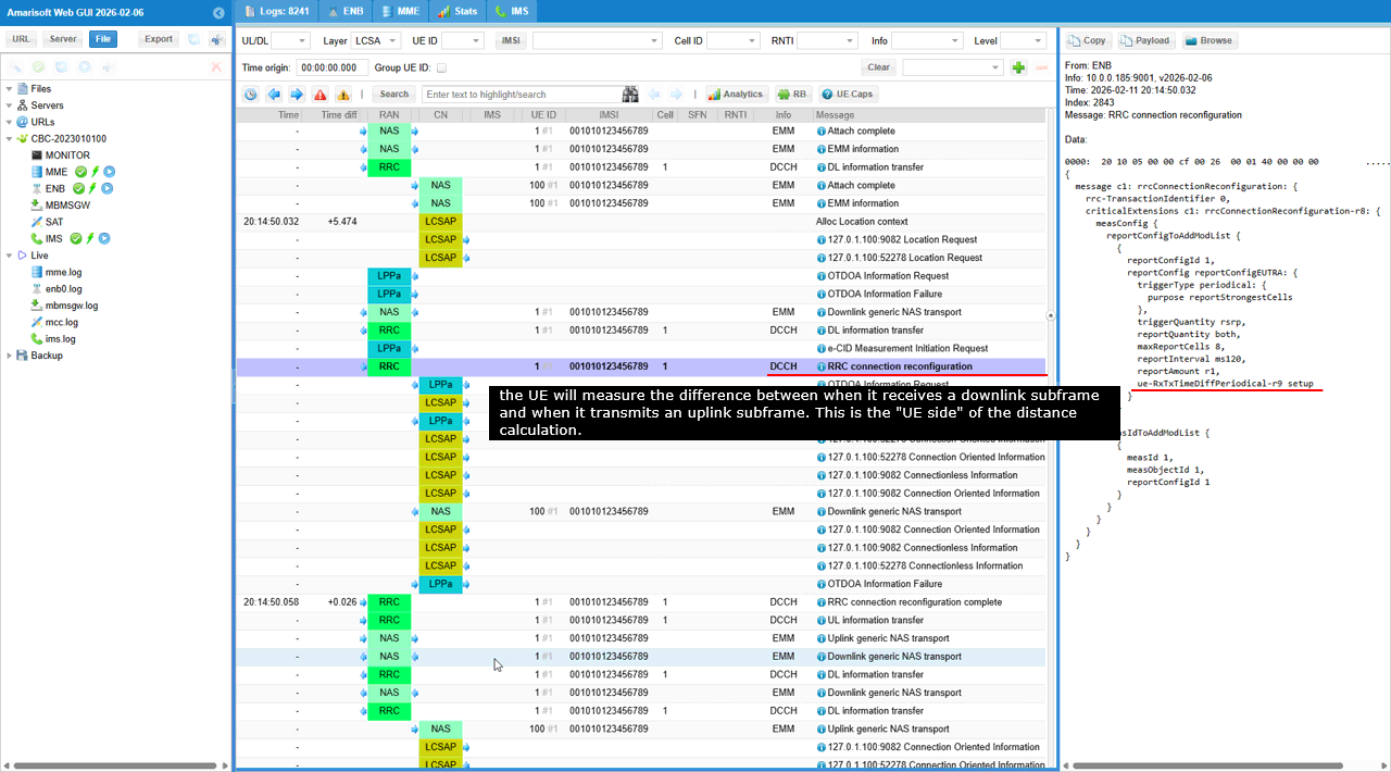
Now the procedure moved from the core network request to the actual RRC (Radio Resource Control) layer configuration. The message underlined in red is the RRC connection reconfiguration. The eNodeB's command to the UE to start the physical measurements required for positioning. While the previous LPPa messages were internal network "talk," this is the specific instruction sent over the air to the phone. In an LPP test context, this reconfiguration is often used to set up Measurement Gaps or specific reporting criteria so the UE can measure neighbor cells without dropping its current data connection.
In the measConfig structure, reportConfigId ties this measurement setup to a specific reporting rule set, and the triggerType=periodical means the UE will keep sending reports using the interval defined by that rule. reportInterval=ms120 is an aggressive rate, so the E-SMLC can receive very fresh snapshots of radio conditions during positioning. triggerQuantity=rsrp tells the UE to rank/select cells to report mainly based on received signal strength. ue-RxTxTimeDiffPeriodical-r9 is the key e-CID enabler because it turns on the UE's Rx-Tx time-difference measurement, where the UE compares its downlink reception timing to its uplink transmission timing, providing the UE-side timing input that supports the network's distance (Timing Advance-related) calculation.
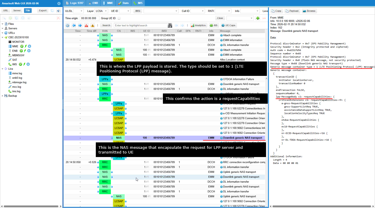
This message represents the transition from network-side preparation to active communication with the device. The E-SMLC (Location Server) uses this message to "tunnel" LPP instructions through the MME and eNodeB to reach the UE. The network is now asking the phone: "What positioning methods are you actually capable of performing?"
This LPP message is a requestCapabilities handshake, so the location server is asking what positioning methods the UE can support (A-GNSS, OTDOA, E-CID, etc.). a-gnss-RequestCapabilities=TRUE means the network is explicitly checking whether the UE can do satellite-based positioning with assistance. otdoa-RequestCapabilities=TRUE means the network still wants the UE's OTDOA capability status for possible later use, even if an OTDOA attempt failed earlier on the network side. ecid-RequestCapabilities=TRUE matches the e-CID workflow you saw before, so the server is confirming the UE can provide the related measurements. transactionID shows the initiator is locationServer, and the UE must reply with ProvideCapabilities using the same transactionID to keep the session aligned. id-Correlation-ID=00000001H is the glue that ties this LPP session back to the original location request, so you can use it to trace the full end-to-end procedure across logs.
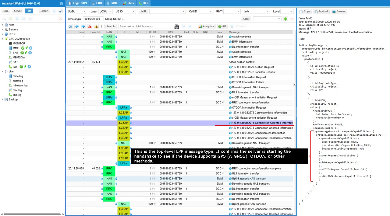
The Downlink generic NAS transport is a NAS-layer message that tunnels the actual positioning instructions. In this specific trace, it is being used to send the LPP RequestCapabilities. This is the handshake phase where the network (specifically the E-SMLC) asks the mobile device, "What hardware sensors and positioning methods do you support?"
The generic message container carries the actual LPP payload, and type=1 tells you this container is an LTE Positioning Protocol (LPP) message. lpp-MessageBody confirms the specific operation is requestCapabilities, meaning the locationServer is starting the capability handshake. a-gnss-RequestCapabilities=TRUE shows the network is checking Assisted-GNSS support, while otdoa-RequestCapabilities={} and ecid-RequestCapabilities={} indicate the server is also probing whether the UE can support OTDOA and Enhanced Cell-ID reporting. transactionID is the session key here: initiator=locationServer and transactionNumber=0, so the UE's next ProvideCapabilities should echo this exact transactionID to keep the LPP exchange correctly matched in your trace.
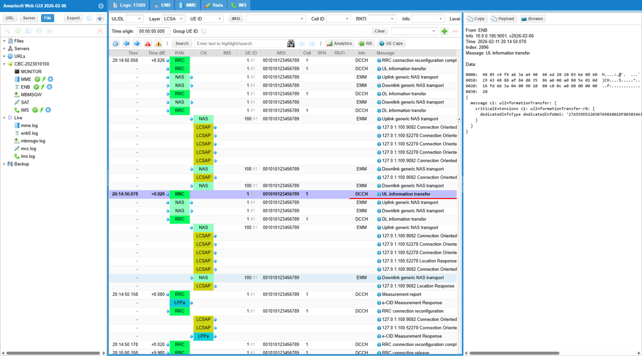
The UL (Uplink) information transfer is an RRC (Radio Resource Control) layer message used by the UE to send non-access stratum (NAS) information to the network. In the context of an LTE LPP test, this specific message acts as a transport container for the UE's response to the network's previous positioning requests. It confirms that the UE has successfully processed the network's instructions and is now sending the required data (such as its positioning capabilities) back to the MME.
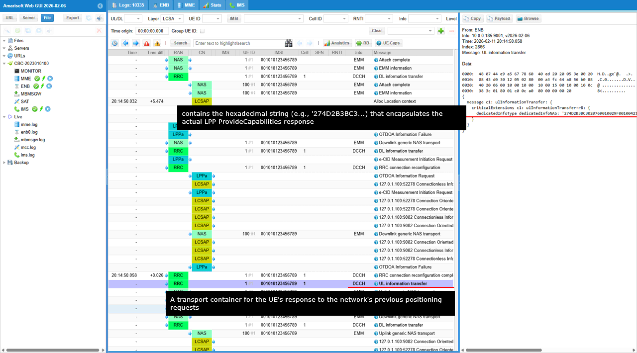
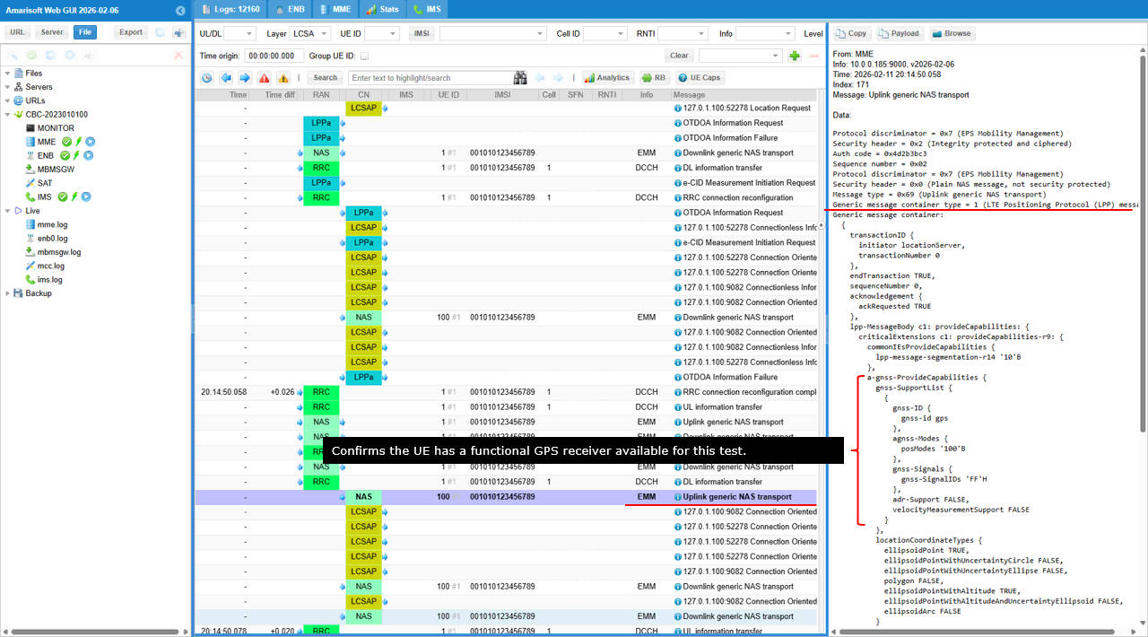
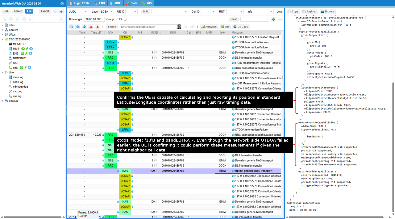
The message is the Uplink generic NAS transport. This is the response to the network's earlier request for capabilities. At this stage, the UE is essentially "auditioning" its sensors, telling the E-SMLC (Location Server) exactly which positioning methods it can perform (GPS, OTDOA, etc.) so the server can decide which one to use for the final location fix.
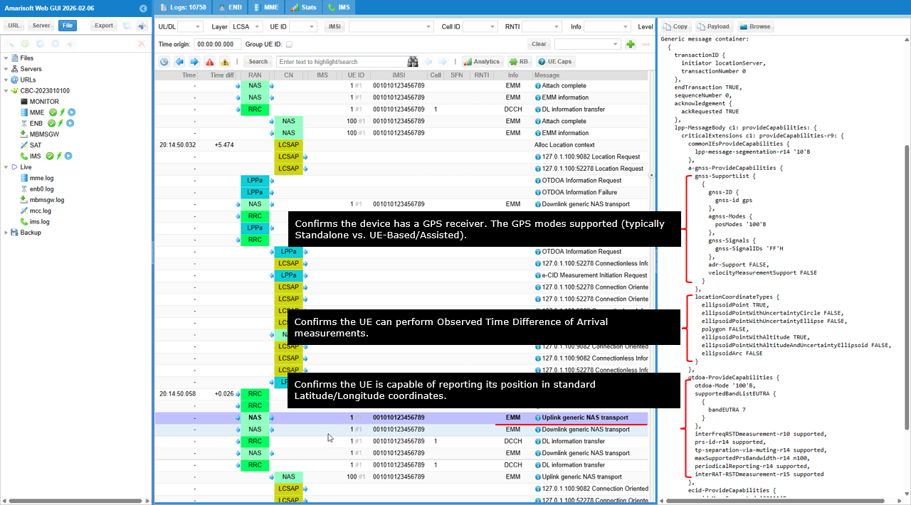
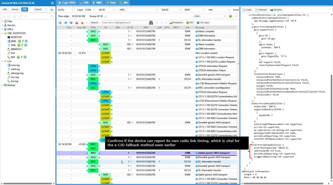
Confirm that lpp-MessageBody: provideCapabilities is present, and first confirm transactionID.transactionNumber=0 to prove this is the UE's direct response to the server's earlier request. In a-gnss-ProvideCapabilities, check gnss-id=gps to confirm a GPS receiver is supported, and then read posModes='10'B to see which GNSS positioning modes the UE claims (standalone vs assisted/UE-based capabilities). In otdoa-ProvideCapabilities, otdoa-Mode='10'B confirms the UE can perform OTDOA measurements, and supportedBandListEUTRA tells you which LTE bands it can use for those timing measurements (for example bandEUTRA 7). ecid-ProvideCapabilities at the bottom is the key confirmation for the fallback path, because it indicates the UE can report the radio timing/related measurements needed for E-CID. Finally, under locationCoordinateTypes, make sure ellipsoidPoint=TRUE, which confirms the UE can report position using standard latitude/longitude coordinates.
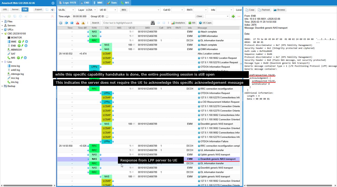
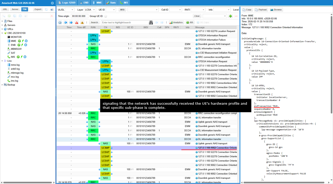
This message is sent by the E-SMLC (Location Server) to the UE to officially acknowledge receipt of the ProvideCapabilities message seen in the previous step. In the LPP state machine, this "closes the loop" on the capability exchange. It tells the UE that the network now has all the hardware information it needs (GPS support, band info, etc.) and is ready to proceed to the next phase, such as providing assistance data or requesting the actual location fix.
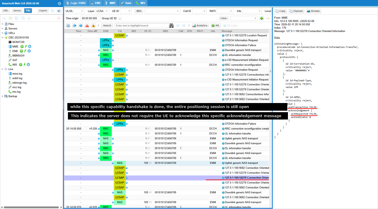
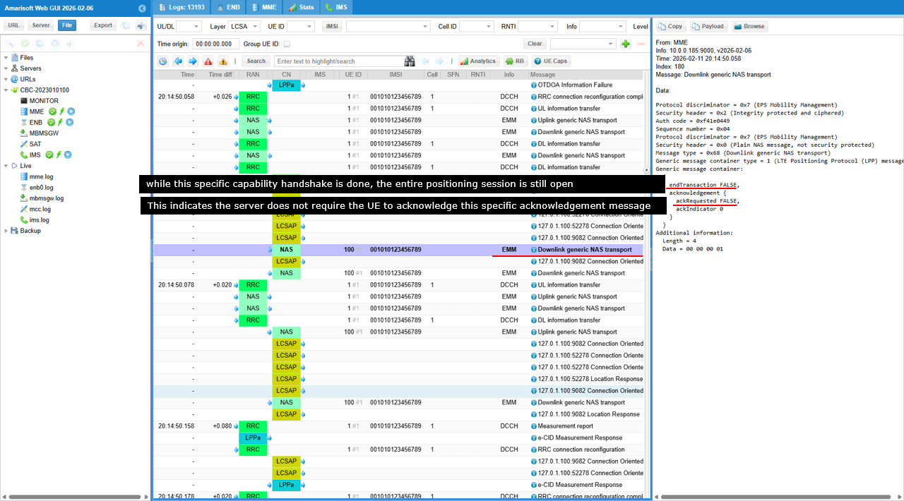
In the Generic message container, acknowledgement shows the location server is explicitly acknowledging the UE's previous LPP transmission. ackRequested=FALSE means the server is not asking the UE to acknowledge this acknowledgement, so the exchange stops cleanly and does not create an ack-of-ack loop. ackIndicator=0 is the key linkage because it points to the transactionID.transactionNumber=0 of the UE message being acknowledged, so you can confirm it matches the capability transaction you are tracking. endTransaction=FALSE is critical for a successful test case because it means only the capability handshake step is complete, while the overall positioning session remains open and the network can send the next LPP instructions (OTDOA, E-CID, A-GNSS assistance, etc.). Finally, Generic message container type=1 confirms the NAS message is still carrying an LPP payload, so the layering and routing are correct.
This message serves as the radio-layer carrier for a response from the Location Server (E-SMLC). Because the actual positioning protocol (LPP) and core network signaling (NAS) cannot be read directly by the physical radio, they are wrapped in this RRC "envelope" to be delivered over the air to the phone.
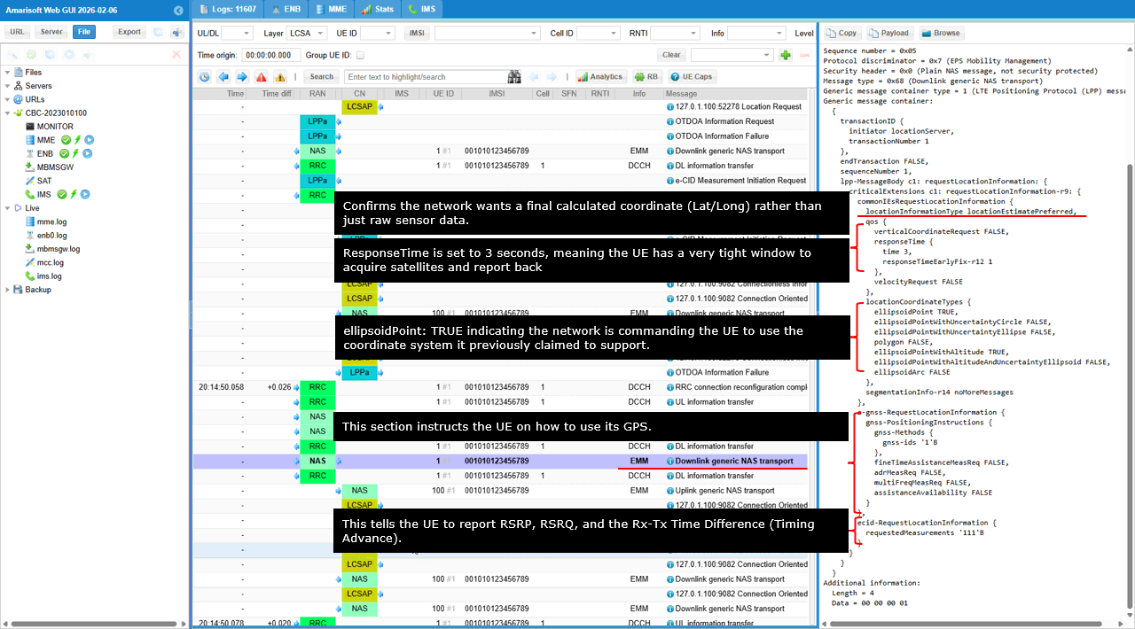
This message represents the "Final Order" in the LPP sequence. The E-SMLC has analyzed the UE's capabilities (like the GPS support confirmed in previous logs) and is now telling the UE: "Perform these specific measurements using your GPS and cell tower sensors, and give me the result."
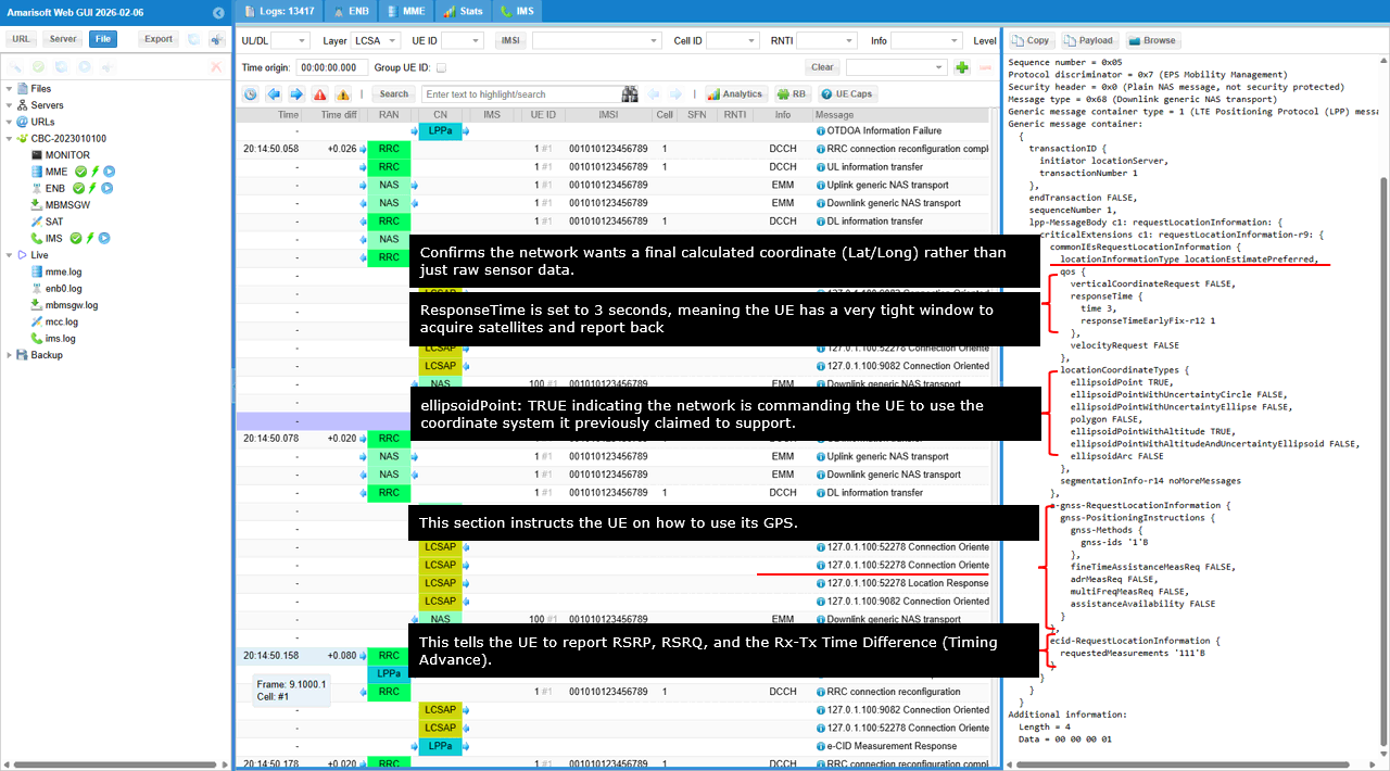
In this LPP request, locationInformationType=locationEstimatePreferred tells you the network wants a final computed position (latitude/longitude), not just raw measurements. The qos.responseTime=3 s is the key stress point of the test, because it gives the UE only a short window to get a GNSS fix before the session times out or falls back. Under locationCoordinateTypes, ellipsoidPoint=TRUE means the network is requesting the UE to report coordinates in the standard lat/long format the UE already advertised. For the actual measurement plan, a-gnss-RequestLocationInformation activates GNSS behavior, and gnss-Methods='1'B specifically triggers the GPS receiver. In parallel, ecid-RequestLocationInformation.requestedMeasurements='111'B is a combined request for RSRP, RSRQ, and UE Rx-Tx time difference (Timing Advance-related), so the network can still produce an E-CID position estimate if GNSS cannot complete within the 3-second QoS window.
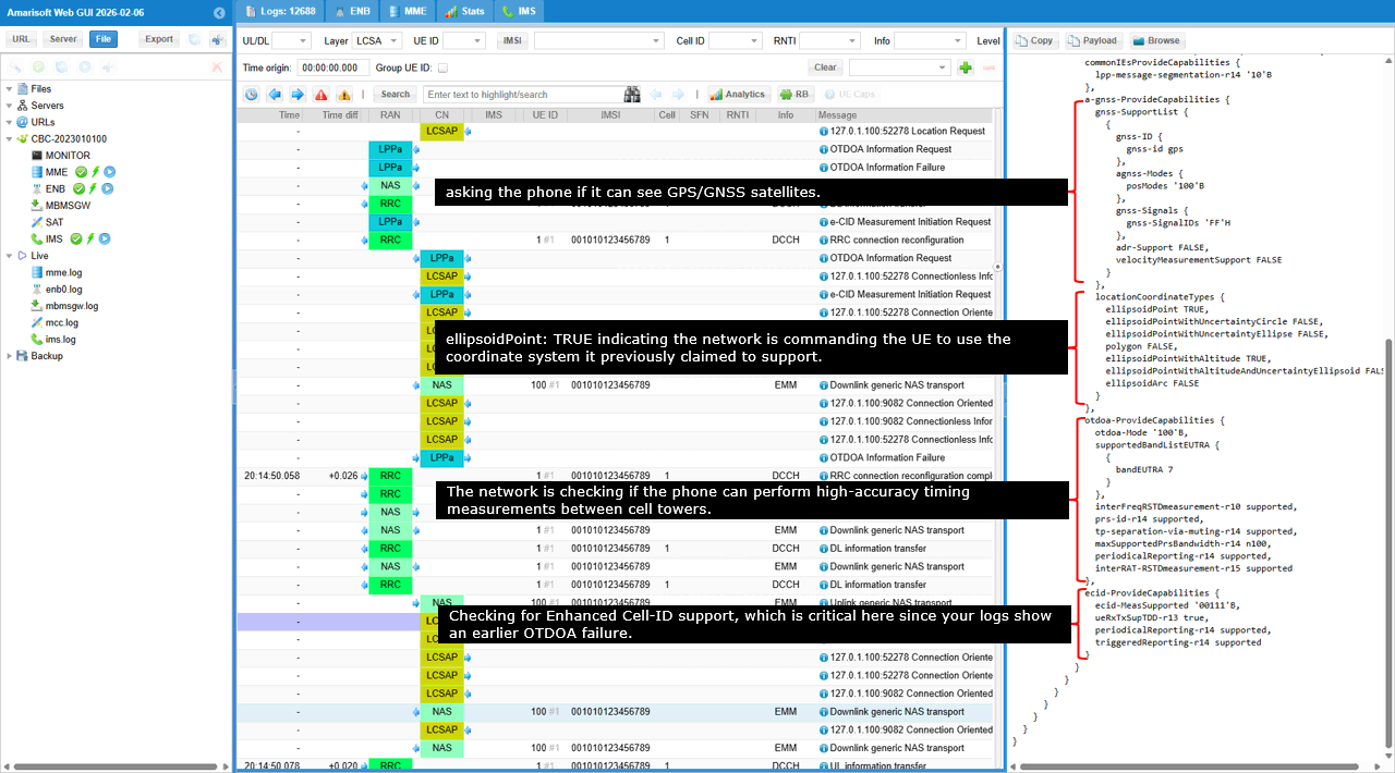
This message is the UE's response to the network's previous request for capabilities. It is the moment the mobile device "introduces" its hardware to the location server. By using Generic NAS Transport, the device can tunnel specialized LPP information through the standard LTE signaling stack without the base station needing to understand the location data itself.
Generic message container type=1 confirms the NAS message is carrying an LPP payload, so the MME treats it as positioning-related signaling rather than general user traffic. Inside the Generic message container, the lpp-MessageBody=provideCapabilities shows this is the UE's capability response. Under a-gnss-ProvideCapabilities, gnss-id=gps confirms the UE has GPS available for this session. Under otdoa-ProvideCapabilities, otdoa-Mode='10'B together with supportedBandListEUTRA (bandEUTRA 7) confirms the UE can perform OTDOA measurements on that LTE band if the network provides valid neighbor/cell assistance data, even if OTDOA failed earlier on the network side. In locationCoordinateTypes, ellipsoidPoint=TRUE confirms the UE can report a calculated position in standard latitude/longitude coordinates. Finally, transactionID.transactionNumber=0 must match the server's original request, proving this provideCapabilities is correctly linked to the same LPP session.
This message is an LCS-AP (Location Services Application Program) protocol unit. It acts as a "container" that tunnels LPP payloads through the MME. In these specific traces, it is used to manage the LPP Capability Exchange�the phase where the network and the mobile device introduce their positioning hardware to one another.
The fields that matter most are id-Correlation-ID (e.g., 00000001H) to tie the whole exchange back to the original location request, id-Payload-Type=lpp to confirm the payload is LPP, and transactionID.transactionNumber (e.g., 0) to keep the request/response paired. endTransaction tells you whether this specific LPP transaction phase is being kept open for follow-on steps (FALSE) or closed/finished (TRUE), and in the requestCapabilities phase you should see a-gnss/otdoa/ecid RequestCapabilities flags set to indicate the network is probing which positioning methods the UE can support (with E-CID typically important as a fallback when OTDOA is problematic).
This message is an LCS-AP protocol container sent from the E-SMLC (Location Server) to the UE. Its primary purpose in this specific log is to acknowledge that the server has successfully received and parsed the UE's previously sent hardware capabilities (such as the GPS and OTDOA support confirmed in the prior uplink message).
This is the DL NAS message that encapsulate the LCSAP message shown above.
This message represents the "Final Order" in the LPP sequence. The E-SMLC has analyzed the UE's capabilities (like the GPS support confirmed in previous logs) and is now telling the UE: "Perform these specific measurements using your GPS and cell tower sensors, and give me the result."
In this LPP request, locationInformationType=locationEstimatePreferred tells you the network wants a final computed position (latitude/longitude), not just raw measurements. The qos.responseTime=3 s is the key stress point of the test, because it gives the UE only a short window to get a GNSS fix before the session times out or falls back. Under locationCoordinateTypes, ellipsoidPoint=TRUE means the network is requesting the UE to report coordinates in the standard lat/long format the UE already advertised. For the actual measurement plan, a-gnss-RequestLocationInformation activates GNSS behavior, and gnss-Methods='1'B specifically triggers the GPS receiver. In parallel, ecid-RequestLocationInformation.requestedMeasurements='111'B is a combined request for RSRP, RSRQ, and UE Rx-Tx time difference (Timing Advance-related), so the network can still produce an E-CID position estimate if GNSS cannot complete within the 3-second QoS window.
This is the RRC package that encapsulate the NAS message from UE.
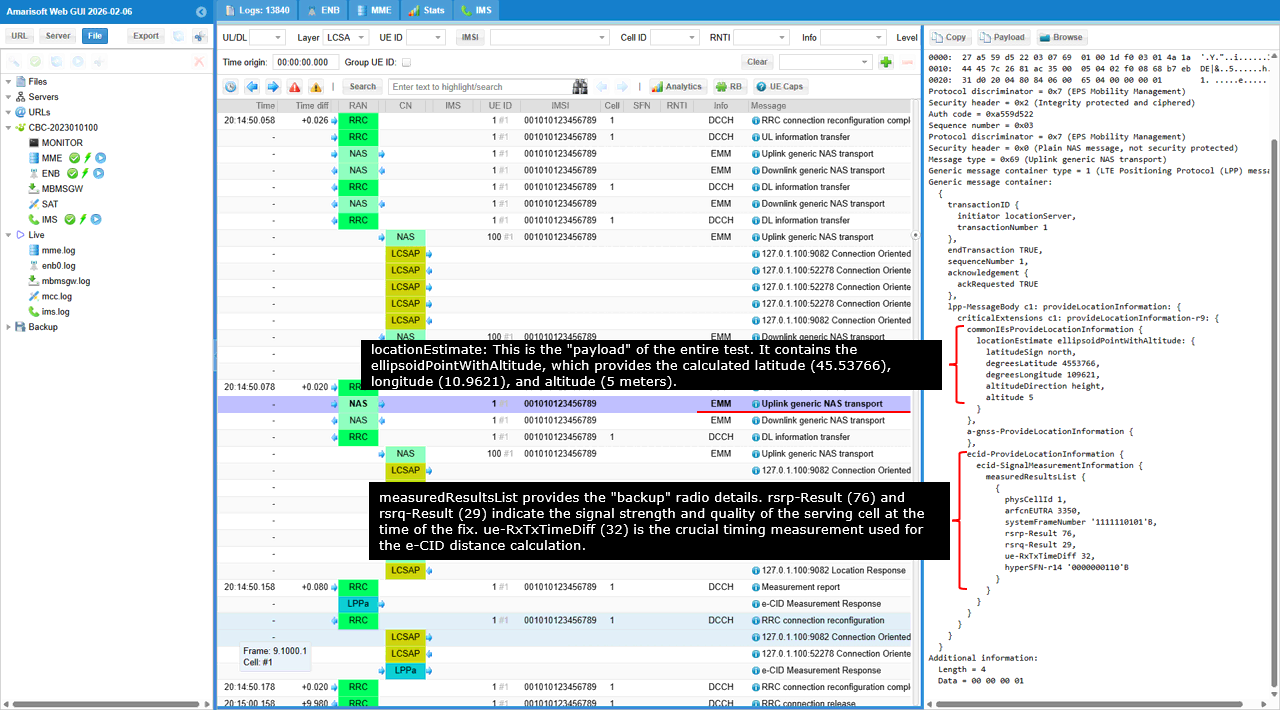
This Uplink generic NAS transport message contains the LPP ProvideLocationInformation payload. This is the most critical message in the test, as it delivers the end results�the physical coordinates and supporting radio measurements�that were requested by the server.
commonIEsProvideLocationInformation.locationEstimate is the main outcome. It should contain ellipsoidPointWithAltitude, showing the final coordinates and height, i.e. latitude 45.53766, longitude 10.9621, and altitude 5 m. a-gnss-ProvideLocationInformation is where GNSS-specific details would appear if the fix was driven primarily by satellite measurements. In this trace, the key point is that the UE produced a valid locationEstimate, consistent with the earlier capability exchange and the request parameters. ecid-ProvideLocationInformation.measuredResultsList provides the radio supporting measurements at the time of the fix: rsrp-Result=76 and rsrq-Result=29 describe serving-cell signal strength and quality, and ue-RxTxTimeDiff=32 is the timing measurement that feeds the E-CID distance component (and acts as the fallback anchor if GNSS is constrained). transactionID.transactionNumber=1 must match the RequestLocationInformation transaction, confirming this result belongs to that exact request. endTransaction=TRUE indicates the network is closing the LPP session for this specific location request, which is what you want to see at the end of a clean, completed test.
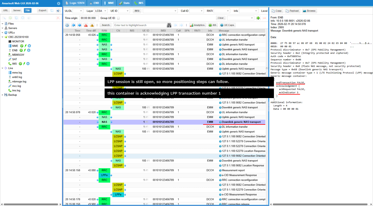
eNB sends Downlink generic NAS transport to carry an LPP payload to the UE. Generic message container type=1 confirms the NAS message is tunneling LTE Positioning Protocol (LPP) data. Inside the generic message container, endTransaction=FALSE means this LPP session is still open, so more positioning steps can follow. ackIndicator=1 means this message is acknowledging the LPP transaction whose transactionID.transactionNumber is 1. In other words, the sender is confirming it received the earlier LPP message that belonged to transaction 1
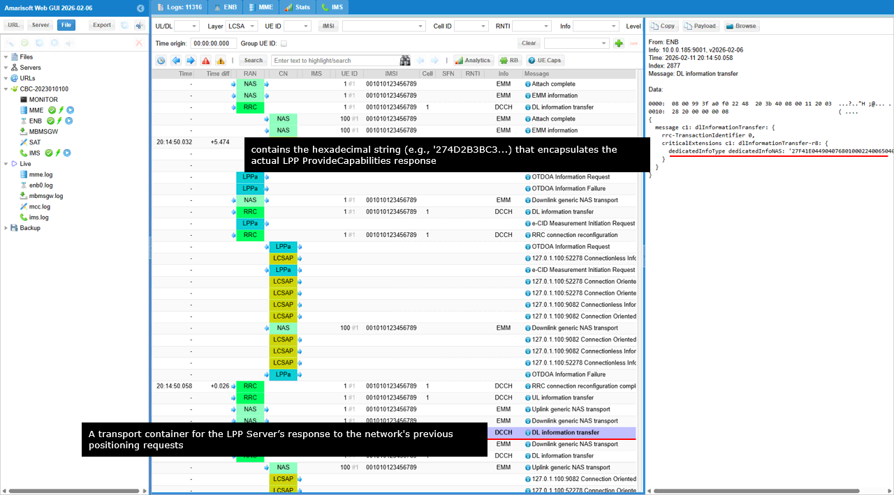
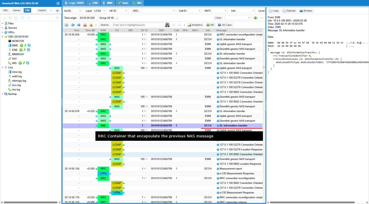
This RRC DL information transfer is to carry a NAS PDU inside an RRC container on the air interface. you can see message c1: dlInformationTransfer-r8, and inside it the dedicatedInfoType: dedicatedInfoNAS field holds the raw NAS bytes
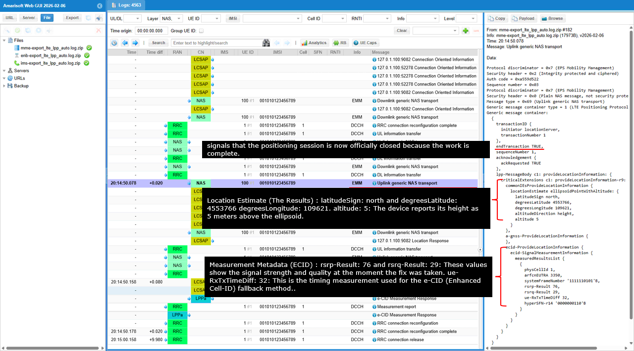
This message acts as a secure container used by the UE to deliver the final LPP Provide Location Information payload back to the network. It contains the physical coordinates (latitude, longitude, and altitude) that were the ultimate goal of the location request.
In the provideLocationInformation result, the key outcome is the location estimate itself: latitudeSign is north and degreesLatitude 4553766 , degreesLongitude 109621 and altitude 5 means the UE reports roughly 5 meters above the ellipsoid. The session linkage is confirmed by transactionID having transactionNumber 1, which must match the earlier RequestLocationInformation so you know this estimate is the response to that command, and endTransaction TRUE indicates the positioning procedure for this request is formally closed. For ECID metadata, rsrp-Result 76 and rsrq-Result 29 capture the serving-cell signal strength and quality at the time of the fix, and ue-RxTxTimeDiff 32 is the UE timing measurement that supports the Enhanced Cell-ID fallback distance component.
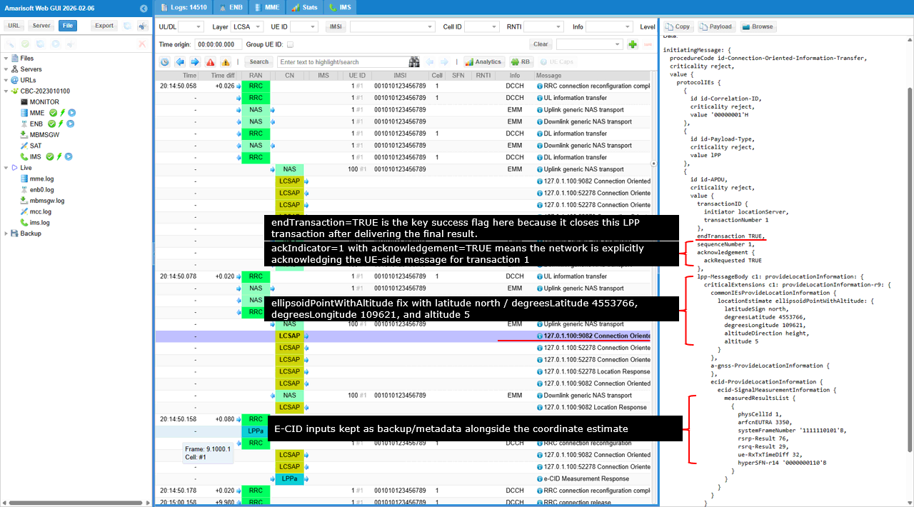
This message is LCSAP Connection-Oriented-Information-Transfer carrying an LPP provideLocationInformation-r9 payload from the locationServer. The id-Correlation-ID=00000001H ties it to the same overall positioning request chain, and id-Payload-Type=lpp confirms the embedded payload is LPP. The transactionID.transactionNumber=1 shows this result belongs to the requestLocationInformation transaction, and ackIndicator=1 with acknowledgement=TRUE means the network is explicitly acknowledging the UE-side message for transaction 1. endTransaction=TRUE is the key success flag here because it closes this LPP transaction after delivering the final result.
Inside commonIEsProvideLocationInformation.locationEstimate, the UE reports an ellipsoidPointWithAltitude fix with latitude north / degreesLatitude 4553766, degreesLongitude 109621, and altitude 5, so the session produced a concrete coordinate output. In ecid-ProvideLocationInformation.measuredResultsList, you also see the supporting radio snapshot for the same instant, including rsrp-Result=76, rsrq-Result=29, and ue-RxTxTimeDiff=32, which are the E-CID inputs kept as backup/metadata alongside the coordinate estimate.
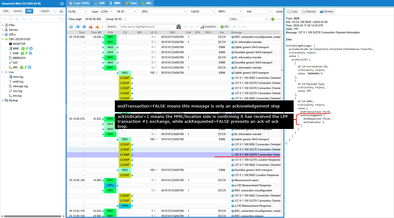
This message is LCSAP Connection Oriented Information sent from the MME, and it is carrying an LPP-related control container identified by id-Payload-Type=lpp with id-Correlation-ID=00000001H, so it belongs to the same positioning session you have been tracing. ackIndicator=1, which means the MME/location side is confirming it has received the LPP transaction #1 exchange, while ackRequested=FALSE prevents an ack-of-ack loop. endTransaction=FALSE means this message is only an acknowledgement step and the overall positioning session is still considered open at the LCSAP transport level, so follow-on LCS/LPP messages can still occur under the same correlation ID.
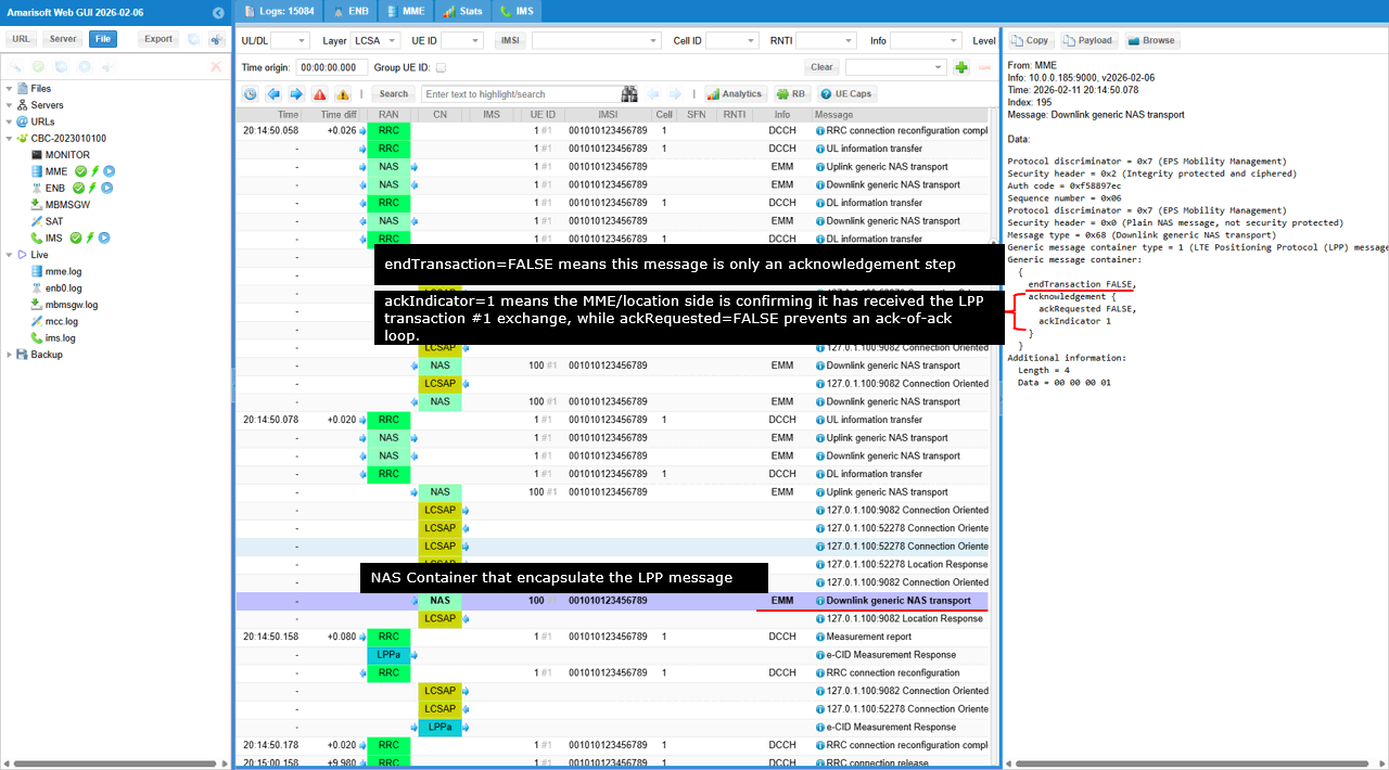
This is the Downlink generic NAS transport which encapsulate the LPP message sent by the server. The Generic message container type=1 means it is carrying an LPP payload. Inside that container, ackIndicator=1 points to LPP transactionNumber 1, so the network side is confirming it received the transaction #1 message. ackRequested=FALSE means it does not ask the UE to acknowledge this acknowledgement, so you do not get an ack-of-ack loop. endTransaction=FALSE means this particular container does not close the overall positioning procedure by itself; it is just an acknowledgement delivery step while the higher-level session context can remain open under the same correlation ID.
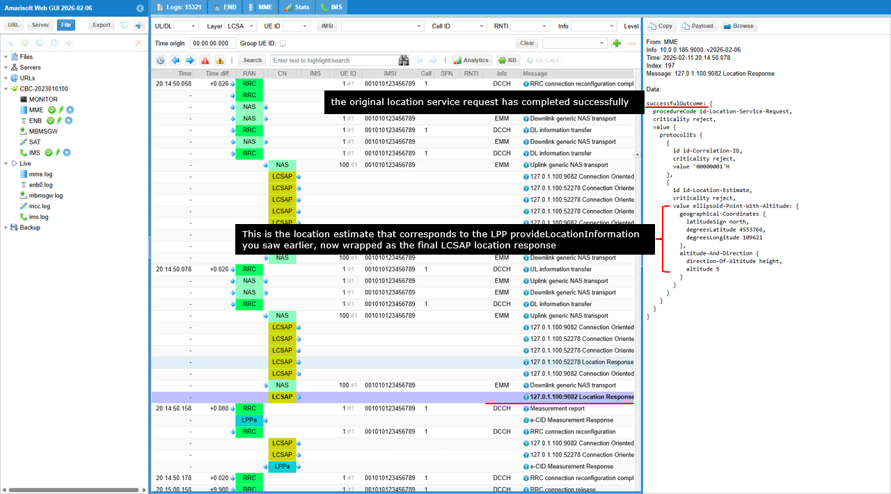
This entry is the LCSAP Location Response coming from the MME toward the E-SMLC/location server side. It is no longer LPP tunneling; it is the final LCSAP response that delivers the computed position back to the requester. In the right pane you can see successfulOutcome with procedureCode = id-Location-Service-Request, which means the original location service request has completed successfully. The id-Correlation-ID = 00000001H confirms it belongs to the same end-to-end session you have been tracking. The actual answer is carried in id-Location-Estimate. It contains ellipsoidPoint-With-Altitude (shown as geographicalCoordinates + altitude), with latitudeSign = north, degreesLatitude = 4553766, degreesLongitude = 109621, and altitude = 5. This is the location estimate that corresponds to the LPP provideLocationInformation you saw earlier, now wrapped as the final LCSAP location response.
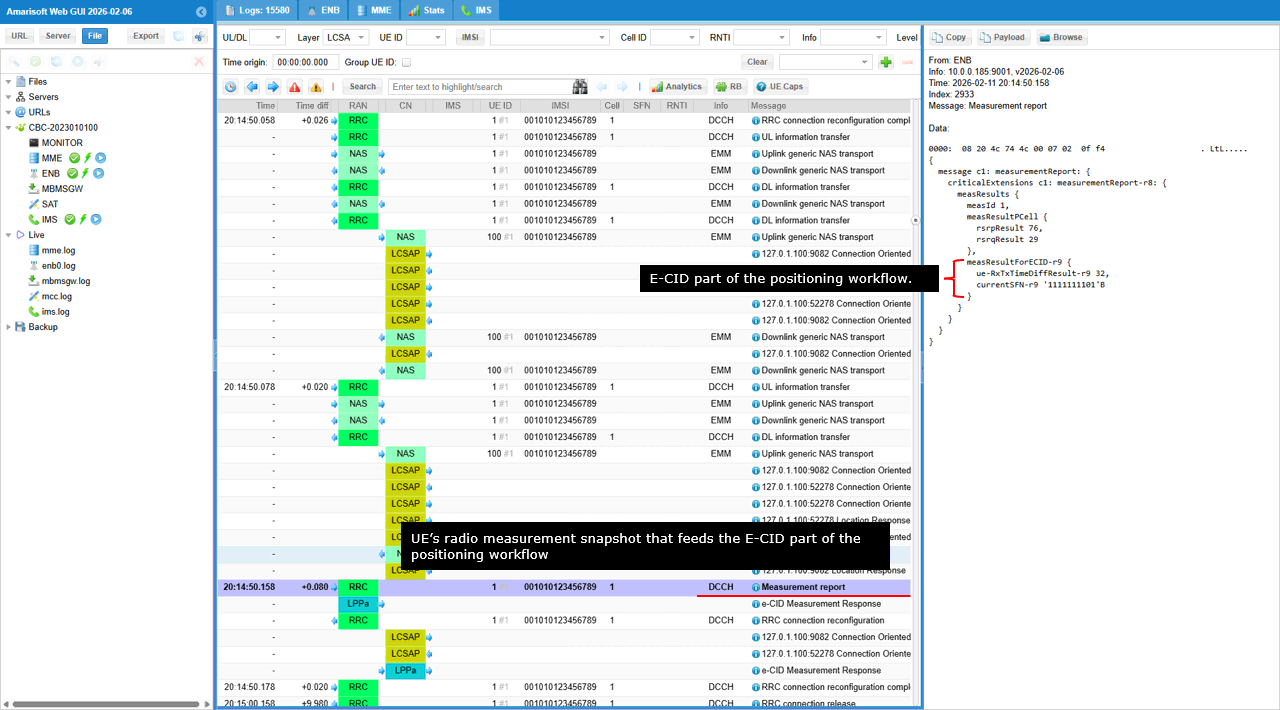
This RRC MeasurementReport is the UE's radio measurement snapshot that feeds the E-CID part of the positioning workflow. In the right pane you can see measurementReport-r8 with measResults, where rsrpResult=76 and rsrqResult=29 report the serving-cell signal strength and quality at that moment. The presence of ue-RxTxTimeDiffResult-r9=32 is the critical e-CID timing input, because it is the UE-reported Rx-Tx time difference that corresponds to the Timing-Advance-related distance component used by the network. The currentSFN value is just the UE's frame timing context for when the measurement was taken, and the key point is that this MeasurementReport is the RRC-level source of the same ECID measurements you later see echoed inside the LPP provideLocationInformation and the final LCS location response.
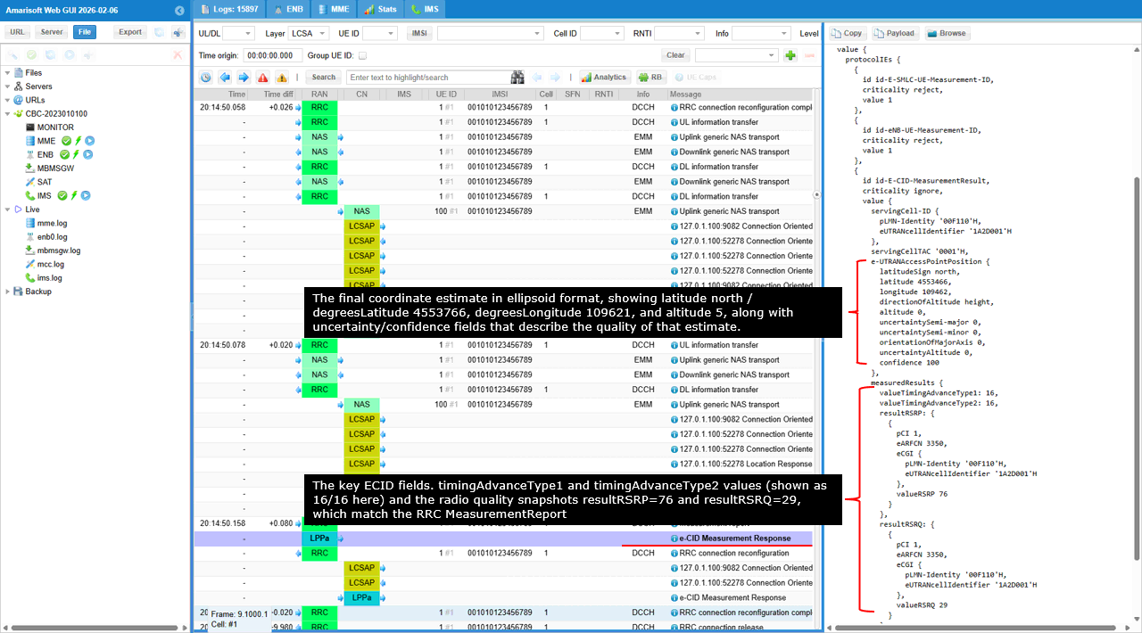
This is the e-CID Measurement Response coming from the positioning side, and it is where the E-SMLC consolidates the UE's radio measurements into a single e-CID result set. In the right pane you can see identifiers like eNB-UE-Measurement-ID and then e-CID-MeasurementResult, which carries both the serving-cell identity context and the outputs that were used to compute the fix.
The servingCell-ID / PLMN-Identity / EUTRANCellIdentifier fields anchor the measurement to the exact LTE cell that acted as the reference. The e-UTRANAccessPointPosition block is the final coordinate estimate in ellipsoid format, showing latitude north / degreesLatitude 4553766, degreesLongitude 109621, and altitude 5, along with uncertainty/confidence fields that describe the quality of that estimate. Under measuredResults, the key e-CID inputs are listed: timingAdvanceType1 and timingAdvanceType2 values (shown as 16/16 here) and the radio quality snapshots resultRSRP=76 and resultRSRQ=29, which match the RRC MeasurementReport you saw earlier and confirm the e-CID path was populated correctly.
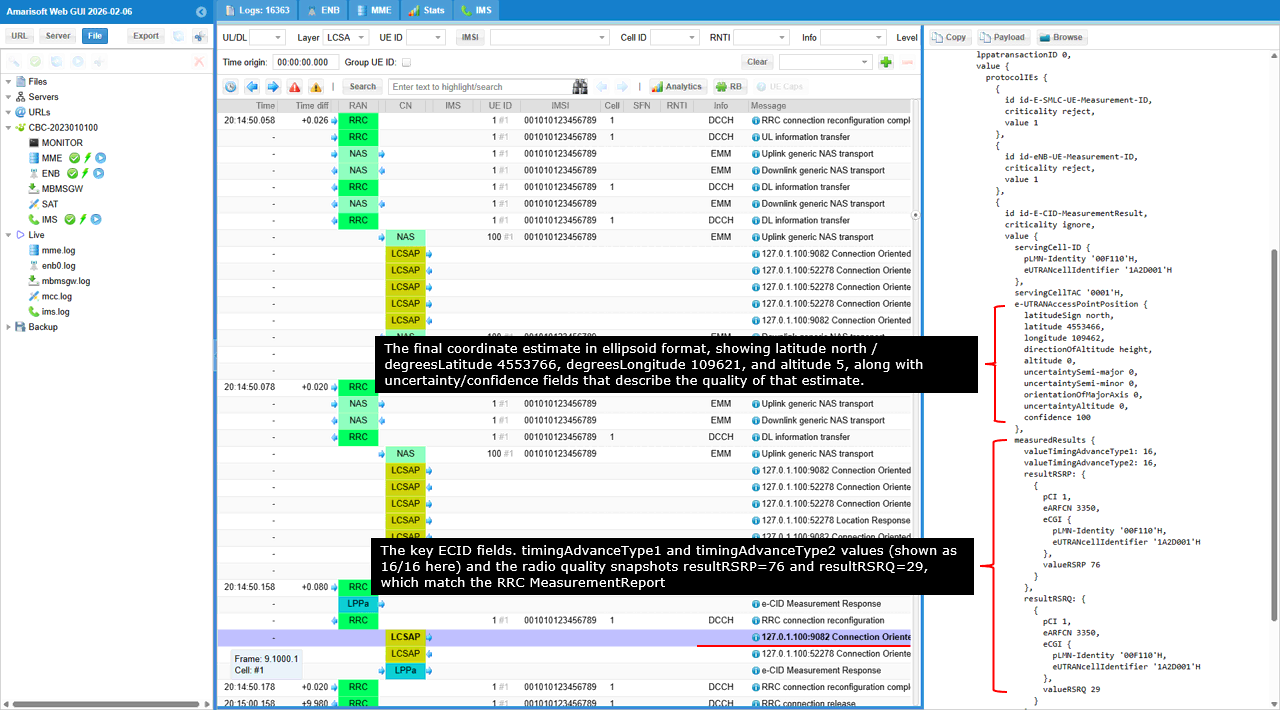
This screen is the MME-side Connection Oriented Information that carries the e-CID measurement result back through LCSAP. The payload starts with lppatransactionID 0 and then lists LCS/e-CID objects such as id-E-SMLC-UE-Measurement-ID, id-eNB-UE-Measurement-ID, and id-E-CID-MeasurementResult.
The servingCell-ID block anchors the result to the serving LTE cell, and the e-UTRANAccessPointPosition block is the coordinate estimate that the positioning function is reporting, showing latitude north with values around 45.54�, longitude around 10.96�, and the altitude field. The measuredResults section carries the radio evidence used for the e-CID computation, including timingAdvanceType1 and timingAdvanceType2 values, and the per-cell resultRSRP=76 and resultRSRQ=29 entries tied to the same ECGI/ARFCN context. The presence of these fields together means the e-CID path is complete: the network has both a position estimate and the measurement snapshot that supports how it was derived.
RRC / NAS Signaling
Downlink generic NAS transport /(LTE Positioning Protocol (LPP) message)
Message: Downlink generic NAS transport
Data:
0000: 27 39 64 3e b7 03 07 68 01 00 0c 90 02 00 fa 02 '9d>...h........
0010: 05 02 c0 e0 14 06 40 65 04 00 00 00 01 ......@e.....
Protocol discriminator = 0x7 (EPS Mobility Management)
Security header = 0x2 (Integrity protected and ciphered)
Auth code = 0x39643eb7
Sequence number = 0x03
Protocol discriminator = 0x7 (EPS Mobility Management)
Security header = 0x0 (Plain NAS message, not security protected)
Message type = 0x68 (Downlink generic NAS transport)
Generic message container type = 1 (LTE Positioning Protocol (LPP) message)
Generic message container:
{
transactionID {
initiator locationServer,
transactionNumber 1
},
endTransaction FALSE,
lpp-MessageBody c1: requestCapabilities: {
criticalExtensions c1: requestCapabilities-r9: {
commonIEsRequestCapabilities {
lpp-message-segmentation-req-r14 '11'B
},
a-gnss-RequestCapabilities {
gnss-SupportListReq TRUE,
assistanceDataSupportListReq TRUE,
locationVelocityTypesReq TRUE
},
otdoa-RequestCapabilities {
},
ecid-RequestCapabilities {
},
nr-ECID-RequestCapabilities-r16 {
},
nr-DL-TDOA-RequestCapabilities-r16 {
}
}
}
}
Additional information:
Length = 4
Data = 00 00 00 01
Uplink generic NAS transport /(LTE Positioning Protocol (LPP) message)
Message: Uplink generic NAS transport
Data:
0000: 27 37 b2 a9 1c 03 07 69 01 00 29 f0 03 00 42 1e '7.....i..)...B.
0010: 80 81 60 28 28 00 0a 3f c4 4a 85 2b 08 84 04 00 ..`((..?.J.+....
0020: c0 02 00 02 00 02 00 02 a0 02 00 02 01 87 05 80 ................
0030: 60 00 70 00 65 04 00 00 00 01 `.p.e.....
Protocol discriminator = 0x7 (EPS Mobility Management)
Security header = 0x2 (Integrity protected and ciphered)
Auth code = 0x37b2a91c
Sequence number = 0x03
Protocol discriminator = 0x7 (EPS Mobility Management)
Security header = 0x0 (Plain NAS message, not security protected)
Message type = 0x69 (Uplink generic NAS transport)
Generic message container type = 1 (LTE Positioning Protocol (LPP) message)
Generic message container:
{
transactionID {
initiator locationServer,
transactionNumber 1
},
endTransaction TRUE,
sequenceNumber 0,
acknowledgement {
ackRequested TRUE
},
lpp-MessageBody c1: provideCapabilities: {
criticalExtensions c1: provideCapabilities-r9: {
commonIEsProvideCapabilities {
segmentationInfo-r14 noMoreMessages,
lpp-message-segmentation-r14 '10'B
},
a-gnss-ProvideCapabilities {
gnss-SupportList {
{
gnss-ID {
gnss-id gps
},
agnss-Modes {
posModes '100'B
},
gnss-Signals {
gnss-SignalIDs 'FF'H
},
adr-Support FALSE,
velocityMeasurementSupport FALSE
}
},
locationCoordinateTypes {
ellipsoidPoint TRUE,
ellipsoidPointWithUncertaintyCircle FALSE,
ellipsoidPointWithUncertaintyEllipse FALSE,
polygon FALSE,
ellipsoidPointWithAltitude TRUE,
ellipsoidPointWithAltitudeAndUncertaintyEllipsoid FALSE,
ellipsoidArc FALSE
}
},
otdoa-ProvideCapabilities {
otdoa-Mode '100'B,
supportedBandListEUTRA {
{
bandEUTRA 7
}
},
interFreqRSTDmeasurement-r10 supported,
prs-id-r14 supported,
tp-separation-via-muting-r14 supported,
maxSupportedPrsBandwidth-r14 n100,
periodicalReporting-r14 supported,
interRAT-RSTDmeasurement-r15 supported
},
ecid-ProvideCapabilities {
ecid-MeasSupported '00111'B,
ueRxTxSupTDD-r13 true,
periodicalReporting-r14 supported,
triggeredReporting-r14 supported
}
}
}
}
Additional information:
Length = 4
Data = 00 00 00 01