LTE - Aperiodic CSI
The purpose of this tutorial is to show you how to configure Aperiodic CQI report in LTE for single carrier and multi carrier environment. When mutiple carriers are being used (especially the number of component carrier is large), to perform the measurement and report for every cell at every reporting occasion can be a big overhead. Aperiodic trigger is a mechanism by which you can select a specific cells to make the report. eNB can define a table with multiple rows in which a specific combination of component carriers for the report are defined in the form of a bitmap. Each of the rows in the table is called 'trigger' in RRC message. Once this trigger is configured, eNB can select a specific trigger when it sends DCI to request aperiodic report.
Overall procedure / mechanism for Aperiodic CSI report can be summarized as follows :
Step 1 : eNB configures the requirement (e.g, type of report item (CQI, PMI, RI) and the list of cells to report)for the report in RRC message
Step 2 : eNB triggers the report using DCI 0 when it wants the report (in DCI, eNB configurethe field 'csi_request' to tell UE to perform the report as specified in RRC message)
Step 3 : UE perform the measurement and send the report via PUSCH
Table of Contents
- LTE - Aperiodic CSI
- Introduction
- Summary of the Tutorial
- Test Setup
- Key Configuration Parameters
- Test 1 : 1 CC
- Test 2: 2CC CA - with Aperiodic CQI
- Configuration
- Perform the Test
- Log Analysis
- Sub Test 1 : 2 Trigger - Same
- Sub Test 2: 2 Trigger - Different
- Test 3: 6CC CA - with Aperiodic CQI
- Configuration
- Perform the Test
- Log Analysis
- Sub Test 1 : 6Trigger - 2 CCs per Trigger
- Sub Test 2: 6Trigger - ArbitraryCCs per Trigger
- RRC / NAS Signaling
- FAQ
Introduction
Aperiodic Channel Quality Indicator (CQI) reporting is a critical feature within the Long Term Evolution (LTE) radio access network, designed to optimize the efficiency and accuracy of link adaptation in both single carrier and carrier aggregation (multi-carrier) environments. In LTE, CQI reports enable the evolved NodeB (eNB) to obtain real-time feedback on the downlink channel conditions from the User Equipment (UE), facilitating dynamic selection of modulation and coding schemes. While periodic CQI reporting provides regular channel state information, aperiodic CQI reporting is initiated by the eNB only when necessary, allowing targeted and flexible measurements that significantly reduce signaling overhead, especially when multiple component carriers are employed. In scenarios involving extensive carrier aggregation, the overhead of simultaneous reporting across all cells can be substantial. To address this, the aperiodic trigger mechanism allows the eNB to configure and select specific subsets of component carriers for reporting, utilizing bitmap-defined trigger tables within the Radio Resource Control (RRC) signaling. Each row in this table, referred to as a 'trigger,' specifies a unique combination of carriers for which the UE should report CQI, Precoding Matrix Indicator (PMI), and Rank Indicator (RI). The eNB, through Downlink Control Information (DCI), signals the UE to generate an aperiodic report based on a selected trigger, thereby achieving granular control over measurement and reporting activities. This mechanism not only streamlines resource utilization but also enhances throughput and reliability in complex carrier aggregation scenarios, playing a pivotal role in the LTE ecosystem's support for high-capacity, high-throughput communication.
-
Context of Aperiodic CQI Reporting in LTE
- Technology Overview: LTE employs link adaptation techniques based on real-time channel feedback, with CQI reporting being key for optimal downlink scheduling.
- Single vs. Multi-Carrier Environments: With carrier aggregation, multiple component carriers are managed simultaneously, increasing complexity in channel state reporting.
- Aperiodic Reporting: Unlike periodic reporting, aperiodic CQI reporting is triggered by the eNB as needed, reducing unnecessary signaling and allowing focused measurements.
-
Relevance and Importance of the Tutorial
- Significance in Network Optimization: Proper configuration of aperiodic CQI reporting is essential for efficient spectrum utilization and maintaining high data throughput, particularly in environments with extensive carrier aggregation.
- Resource Efficiency: The aperiodic trigger mechanism minimizes reporting overhead, preserving uplink resources, and enabling scalable performance as the number of component carriers grows.
- Critical for Advanced LTE Deployments: Mastery of aperiodic CQI configuration supports advanced features in LTE-Advanced and is foundational for transitioning to 5G NR.
-
Learning Outcomes
- Understand the architectural flow of aperiodic CQI reporting in LTE, including interactions between eNB and UE.
- Gain hands-on experience configuring aperiodic CQI triggers for both single and multi-carrier scenarios using RRC signaling.
- Learn how to interpret and apply DCI messages to selectively trigger aperiodic CQI reports.
- Acquire troubleshooting skills for common issues in CQI reporting configuration and operation.
-
Prerequisite Knowledge and Skills
- Familiarity with LTE architecture, including the roles of eNB and UE.
- Understanding of LTE physical layer concepts such as CQI, PMI, RI, and carrier aggregation.
- Basic knowledge of RRC signaling and DCI formats in LTE specifications.
- Experience with radio network configuration and analysis tools is beneficial but not mandatory.
Summary of the Tutorial
This tutorial outlines procedures for testing LTE Carrier Aggregation (CA) and Aperiodic Channel Quality Indicator (CQI) reporting using Amarisoft eNB and multiple SDR cards. The document describes several test scenarios with varying configurations of component carriers (CC), focusing on enabling and verifying aperiodic CQI reports across different CA setups.
-
Test 1: 1 CC – Aperiodic CQI Reporting
- Configure the system with a single LTE cell, using the enb_1cc_ap_cqi.cfg without modifications and mme-ims.cfg as is.
- Set up only one SDR card with an antenna.
- Periodic CSI report is disabled (set cqi_period and m_ri to 0); enable aperiodic CSI report via ap_cqi_period and ap_cqi_rm.
- Verify cell configuration using 'cell phy' and 'cell' commands.
- Check logs for proper CQI report settings in the RRC Connection Reconfiguration message.
- Identify DCI 0 with csi_request set to a non-zero value, ensuring UE sends PUSCH with aperiodic CQI report as configured.
-
Test 2: 2CC CA – Aperiodic CQI with Multiple Triggers
- Configure two LTE FDD cells for carrier aggregation, using enb-2cc-ap-cqi-trigger.cfg (modified from enb-2cc.cfg).
- Each cell’s scell_list includes the other as an SCC.
- Enable aperiodic CSI reporting; periodic CSI is disabled by omitting cqi_period and m_ri.
- Verify cell setup with 'cell phy' and 'cell' commands.
- Analyze logs for aperiodic trigger configuration in RRC, including trigger interpretation from aperiodicCSI-Trigger IE.
- Check establishment of carrier aggregation and that PUSCH transmissions contain requested CSI reports per DCI 0 triggers.
-
Sub Test 1: 2 Triggers – Same Configuration
- Configure two triggers with identical settings using ap_cqi_trigger_list.
- Confirm correct trigger application through log analysis, ensuring PUSCH reporting matches trigger requests.
-
Sub Test 2: 2 Triggers – Different Configuration
- Set two triggers with different configurations in ap_cqi_trigger_list.
- Verify through logs that each DCI 0 uses the appropriate trigger and that UE responds with correct CSI reports.
-
Test 3: 6CC CA – Aperiodic CQI with Advanced Triggering
- Configure six LTE FDD cells using enb-6cc-ap-cqi.cfg (derived from gnb-nsa.cfg), ensuring all six SDR cards are connected and configured.
- Each cell’s scell_list includes all other cells for full CA.
- Enable aperiodic CSI reporting by setting ap_cqi_period and ap_cqi_rm, leaving ap_cqi_trigger_list at defaults unless otherwise specified.
- Verify all six cells are correctly configured using 'cell phy' and 'cell' commands.
- Analyze logs for correct aperiodic trigger settings in RRC, and observe round-robin trigger use in DCI 0 scheduling (only triggers with non-all-zero values are used).
-
Sub Test 1: 6 Triggers – 2 CCs per Trigger
- Use enb-6cc-ap-cqi_trigger_2perTrigger.cfg to configure six triggers, each activating two component carriers.
- Confirm via logs that triggers are utilized in round-robin fashion and that the UE sends CSI reports as required by each DCI 0 trigger.
-
Sub Test 2: 6 Triggers – Arbitrary CCs per Trigger
- Use enb-6cc-ap-cqi_trigger_arbTrigger.cfg to define six triggers, each with a different number of enabled component carriers.
- Verify correct mapping and utilization of triggers in DCI 0 and monitor that the CSI reporting by UE aligns with each trigger configuration.
General Log Analysis and Verification Steps:
- Convert trigger values in aperiodicCSI-Trigger IE from hex to binary to determine exact trigger settings for each component carrier.
- Ensure correct establishment of carrier aggregation by inspecting sCellToAddModList in RRC messages.
- Match DCI 0 csi_request values with the expected triggers and verify that PUSCH transmissions from the UE contain the requested CQI/RI reports.
- Interpret ap_cqi_trigger_list configuration and its RRC mapping as described in the tutorial FAQ.
Summary: The tutorial provides clear methodologies for configuring and verifying aperiodic CQI reporting in single and multi-carrier LTE deployments, with step-by-step procedures for system setup, configuration, test execution, and log analysis. Special attention is paid to the translation of configuration parameters to RRC signaling and the correct operation of multiple triggers in carrier aggregation scenarios.
Test Setup
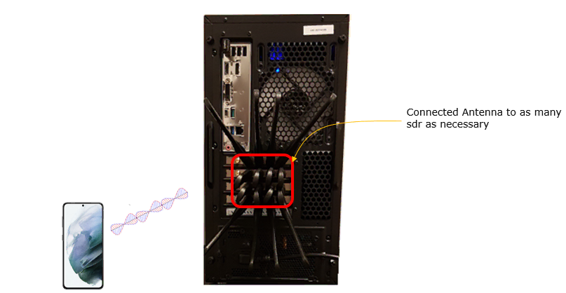
Test setup for this tutorial is as shown below. In this setup, it shows 4 SDR cards are connected with Antenna but not all the test in this tuturial requires the 4 sdr cards. You only have to connect antenna to the number of sdr cards that you need for each test.
Key Configuration Parameters
Followings are important configuration parameters for this tutorial. You may click on the items for the descriptions from Amarisoft documents.
- scell_list: In this link, you will get the descriptions for all the items listed below.
- cell_id
- cross_carrier_scheduling
- scheduling_cell_id
- ul_allowed
- rrc_configuration
- individual_offset
- ap_cqi_period
- ap_cqi_trigger_list
- ap_cqi_rm
- ap_cqi_rm_opt
Test 1 : 1 CC
This test configures 1 LTE Cell with the configuration of Aperiodic CQI Report
Configuration
In this test, I used enb_1cc_ap_cqi.cfg without modification.

I used the mme-ims.cfg config as it is.

The configuration in enb_1cc_ap_cqi.cfg is as shown below.
In this test, only one cell is configured in cell_list and you don't need any specific configuration here. Just set whatever frequency and band that your DUT supports.
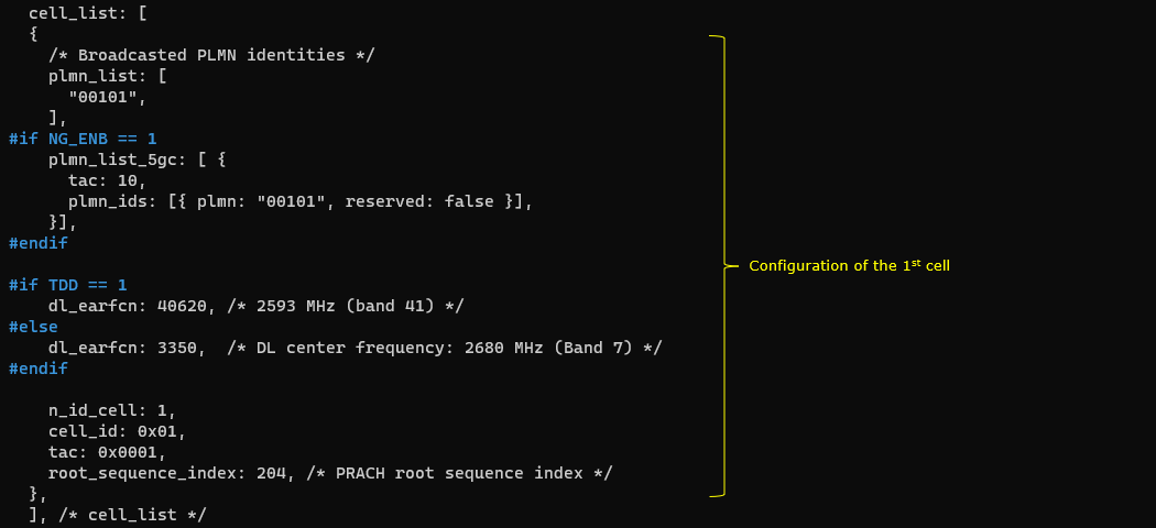
In cell default configuration, periodic CSI report is disabled by setting cqi_period and m_ri to 0. And Aperiodic CSI report is enabled by configuring ap_cqi_period and ap_cqi_rm.

Perform the Test
Check out cell configuration with 'cell phy' and 'cell' command and make it sure that all the cells are configured as intended.

NOTE : you may not always see the print for CC=1 because the print shown here is a sampled / averaged. You may take it as success as long as you see the print for CC = 2.

Log Analysis
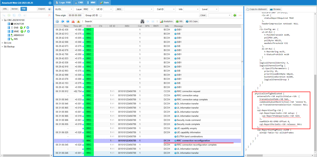
Check out the cqi report is enabled or disabled as intended by checking out physicalConfigDedicated in RRC connection Reconfiguration message.
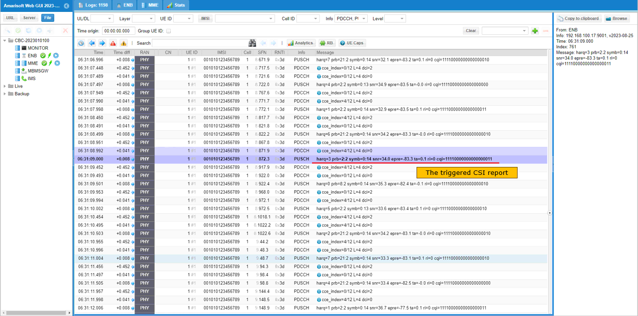
Find a DCI 0 with csi_request set to Non-zero value. This triggers UE to send PUSCH with Aperiodic CQI report. Here it request CSI report configured by Serving cell. (Check out this noteto figure out how csi_request value is translated to trigger number)
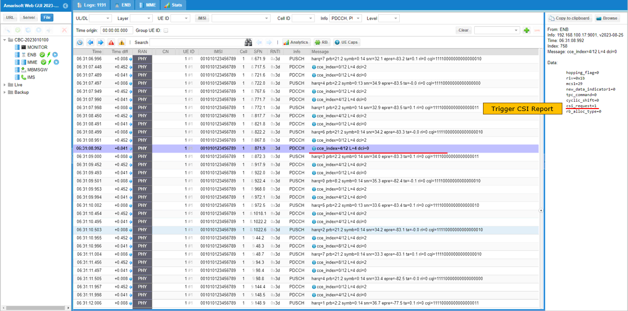
Check out the triggered Apperiodic report by checking PUSCH with csi rpoert(ri, cqi).
Test 2: 2CC CA - with Aperiodic CQI
This test configures 2cells as follows.
- 2 LTE FDD Cells
It performs following procedure
Step 1 : Initial Attach to LTE
Step 2: Establish 2CC CA in LTE with Aperiodic CQI
Configuration
In this testI used the enb-2cc-ap-cqi-trigger.cfg which is copied and modified from enb-2cc.cfg


Followings are the configurations in enb-2cc-ap-cqi-trigger.cfg
Set CQI_CONFIG 1 to enable Aperiodic CSI Report.

In this test, only twocell areconfigured in cell_list for carrier aggregation. So each of the cell has scell_list in the configuration that specifies all the other cells as SCC(Secondary Component Carrier).
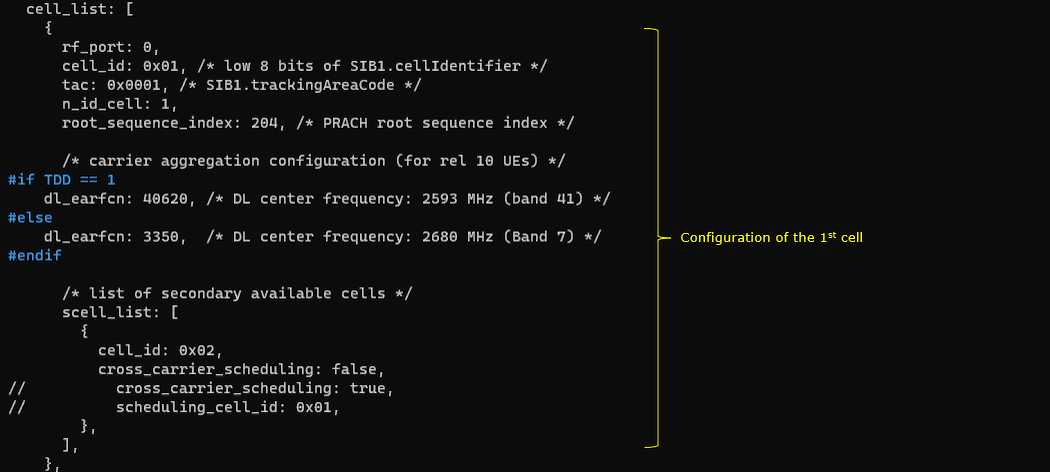
This is the configuration for the first cell (cell_id 1), so the 2nd cell(cell_id 2) is registered in scell_list
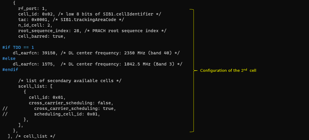
This is the configuration for the 2ndcell (cell_id 2), so the 1st cell(cell_id 1) is registered in scell_list
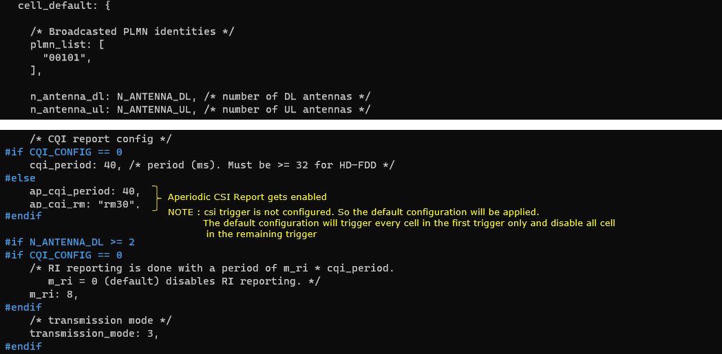
In cell default configuration, periodic CSI report is disabled by skippingcqi_period and m_ri setting. And Aperiodic CSI report is enabled by configuring ap_cqi_period and ap_cqi_rm. In this test, csi trigger is not configured indicating that the default trigger setting will be applied.
Perform the Test
Check out cell configuration with 'cell phy' and 'cell' command and make it sure that all the cells are configured as intended.

NOTE : you may not always see the print for CC=1 because the print shown here is a sampled / averaged. You may take it as success as long as you see the print for CC = 2.

Log Analysis
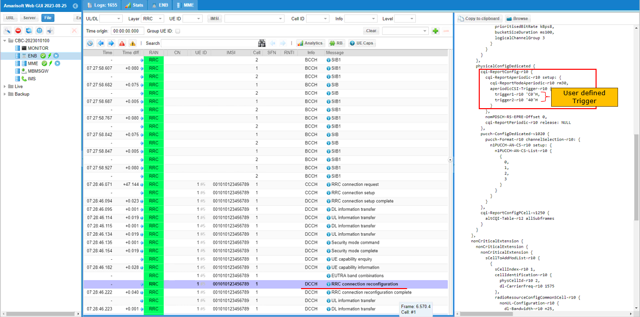
Check out Aperiodic Trigger setting in RRC Connection Reconfiguration. Convert the Hex number of each trigger in aperiodicCSI-Trigger IE into binary and you would figure out the trigger settings for each CC (Component Carrier).
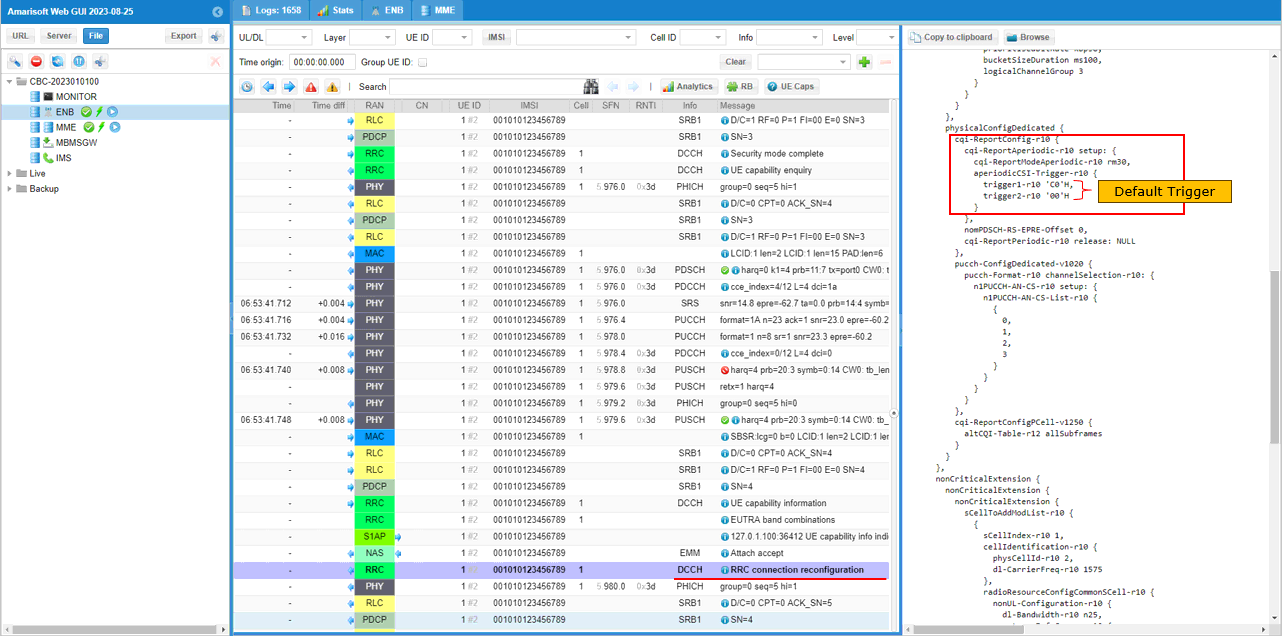
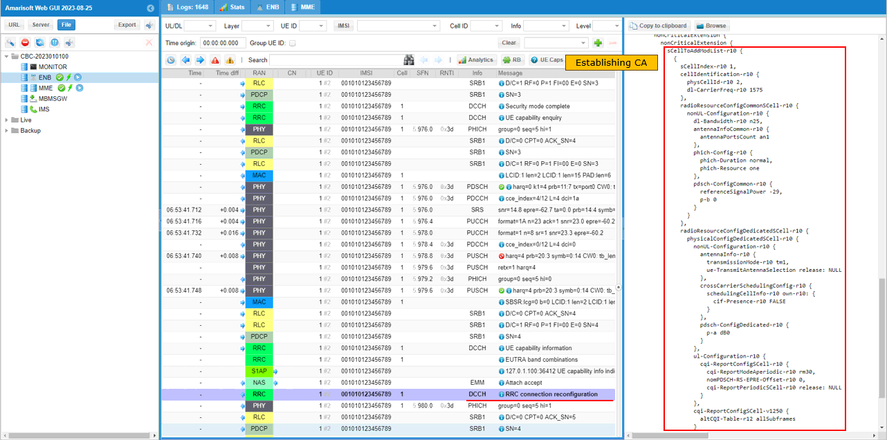
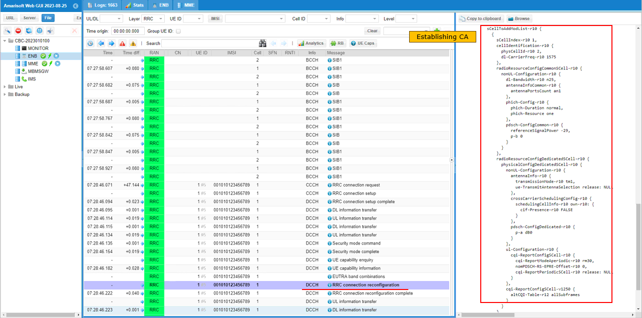
Check if Carrier Aggregation is established as intended by checking out sCellToAddModList in Rrc Connection Reconfiguration message.
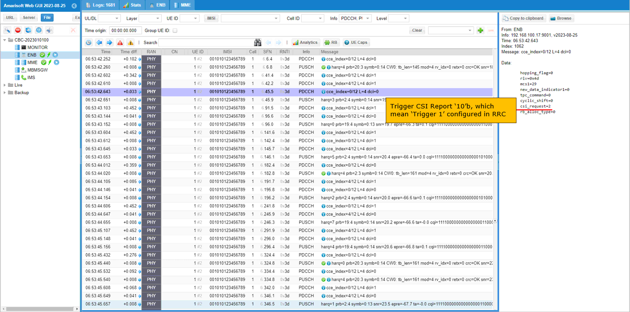
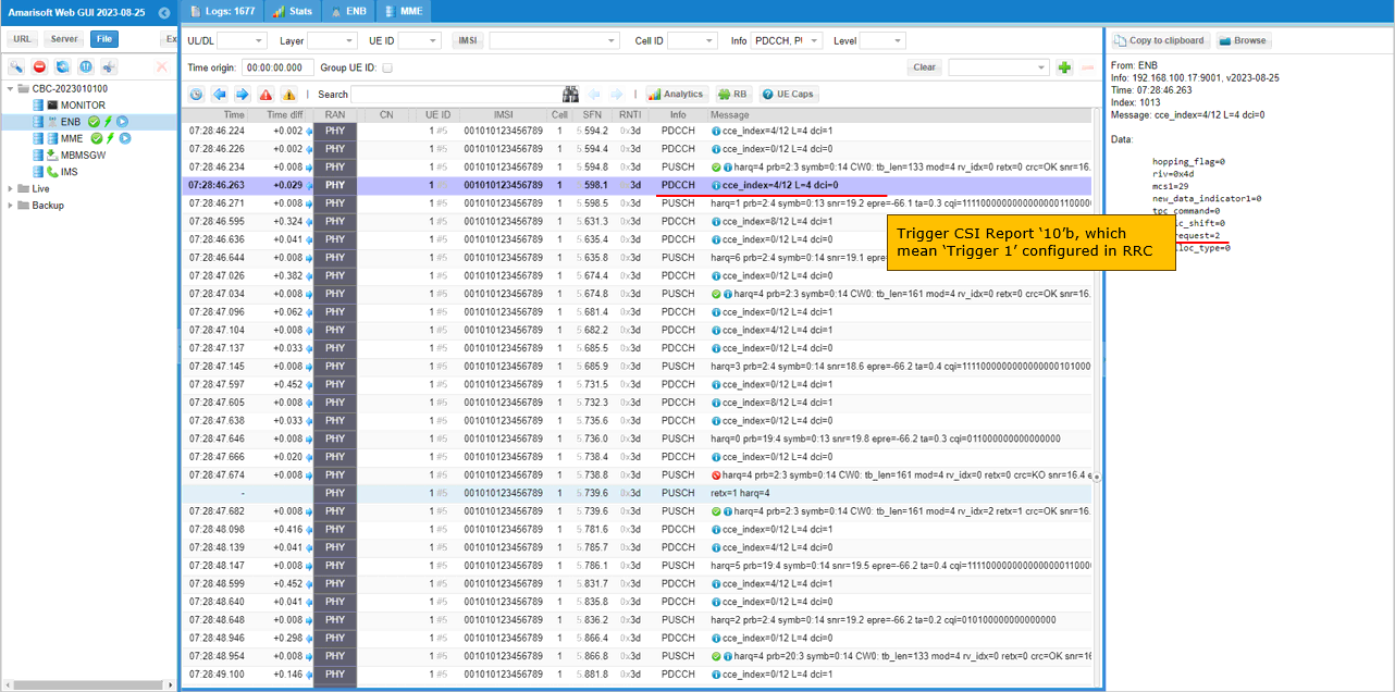
Find a DCI 0 with csi_request set to Non-zero value. This triggers UE to send PUSCH with Aperiodic CQI report. Here it request CSI report configured by Trigger 1. (Check out this noteto figure out how csi_request value is translated to trigger number)
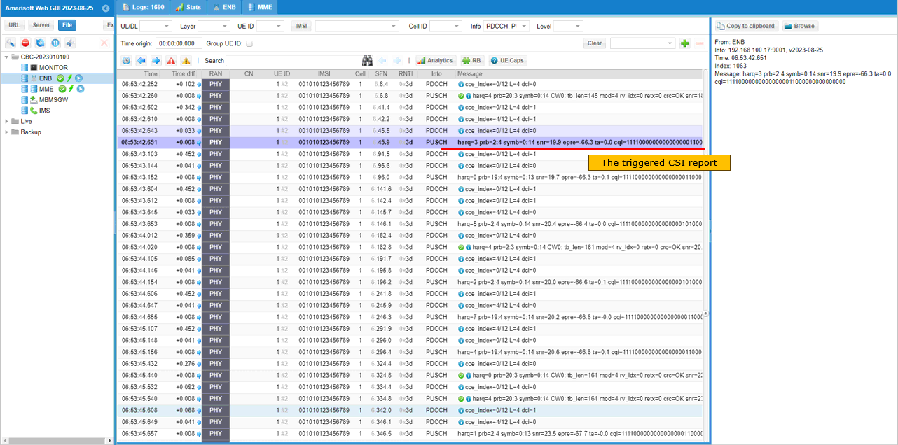
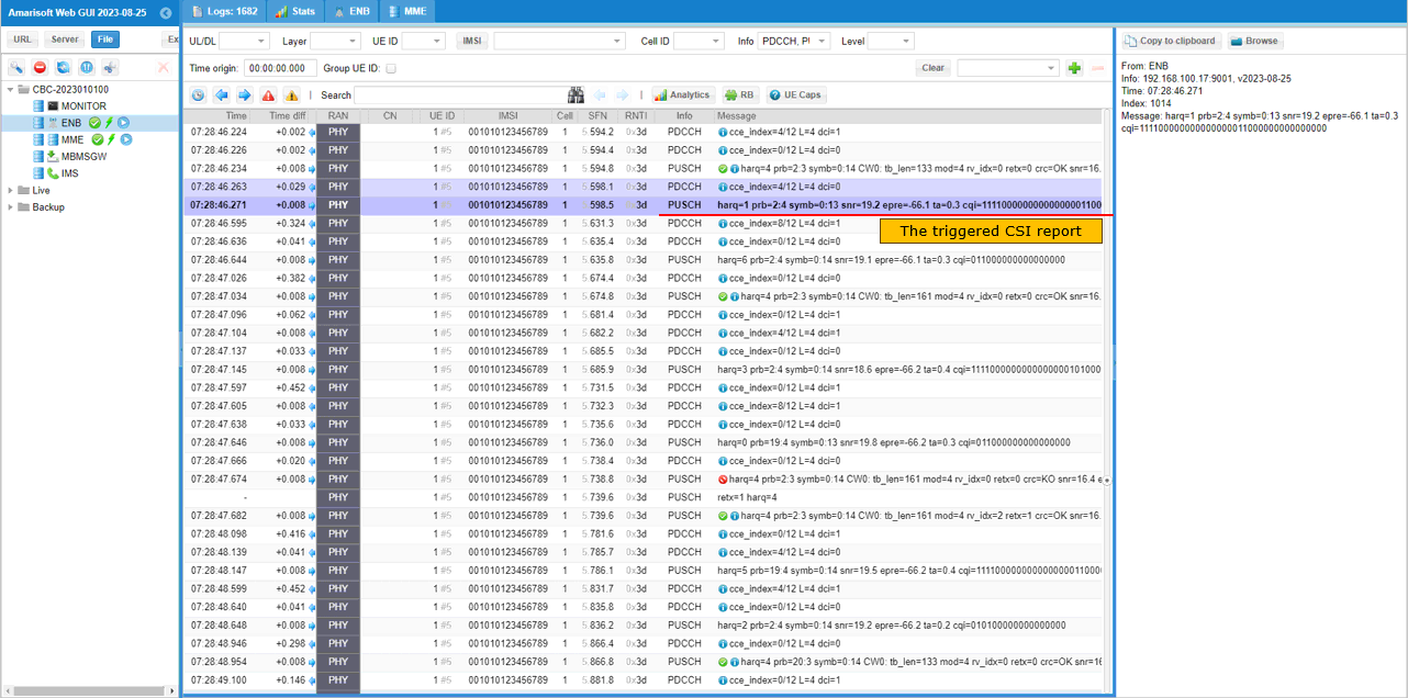
Find the PUSCH that carries CSI report (ri, cqi) that are requestedby the DCI.
Sub Test 1 : 2 Trigger - Same
In this sub test, I will show you an example of setting two triggers of same configuration.
In cell default configuration, periodic CSI report is disabled by skippingcqi_period and m_ri setting. And Aperiodic CSI report is enabled by configuring ap_cqi_period and ap_cqi_rm. In this test, ap cqi trigger is configured by setting ap_cqi_trigger_list.
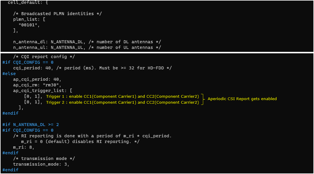
Check out Aperiodic Trigger setting in RRC Connection Reconfiguration. Convert the Hex number of each trigger in aperiodicCSI-Trigger IE into binary and you would figure out the trigger settings for each CC (Component Carrier).
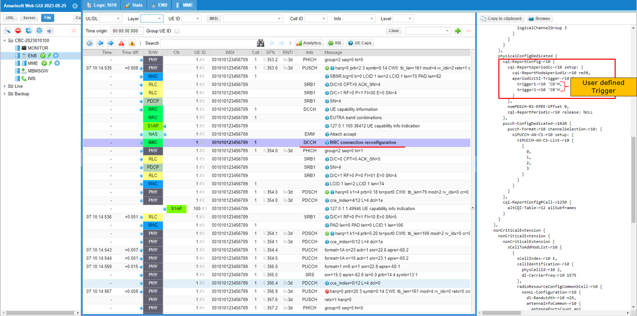
Check if the carrier aggregation is configured as intended by checking out sCellToAddModList IE in RRC Connection Reconfiguration message.
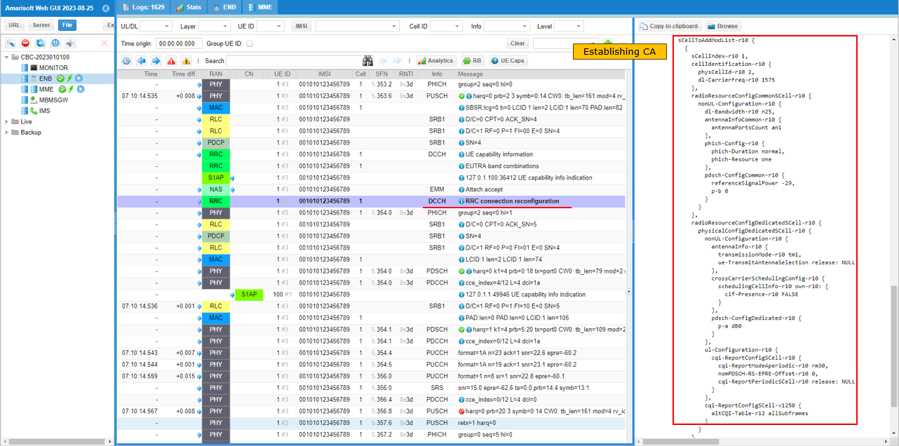
Find a DCI 0 with csi_request set to Non-zero value. This triggers UE to send PUSCH with Aperiodic CQI report. Here it request CSI report configured by Trigger 1. (Check out this noteto figure out how csi_request value is translated to trigger number)
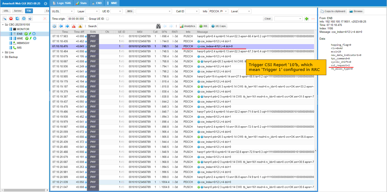
Find the PUSCH that carries CSI report (ri, cqi) that are requestedby the DCI.
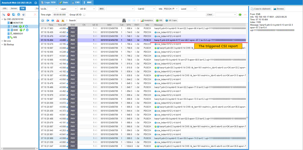
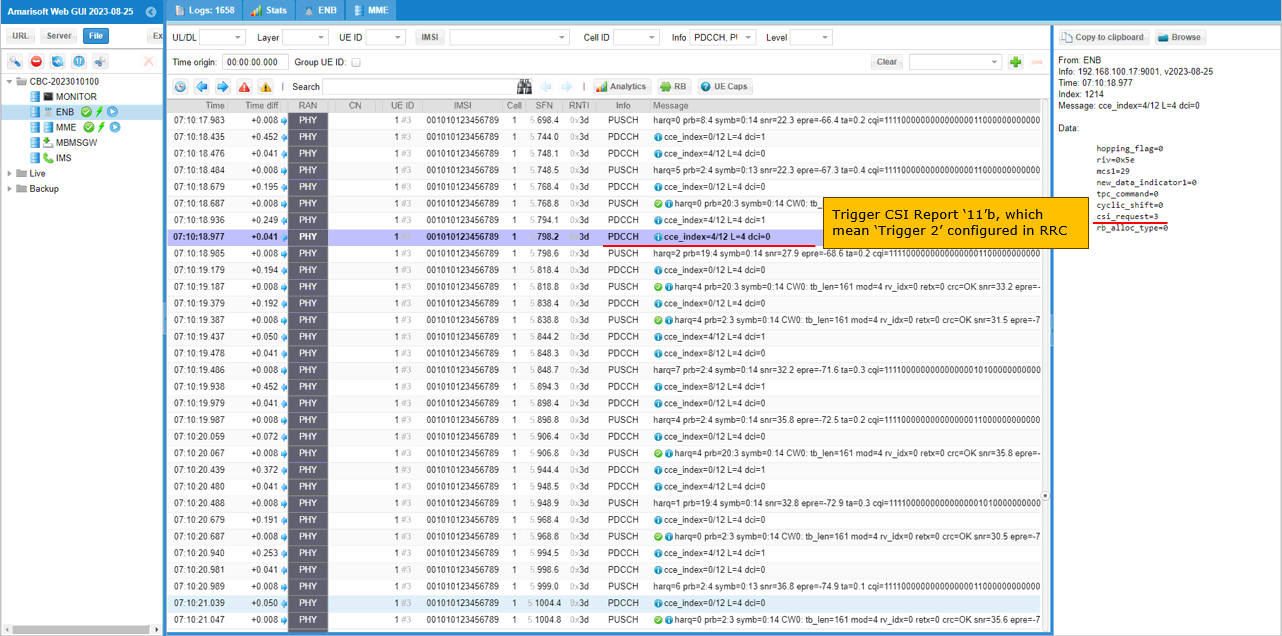
Find a DCI 0 with csi_request set to Non-zero value. This triggers UE to send PUSCH with Aperiodic CQI report. The value in binary indicates the trigger number configured in RRC. This triggers UE to send PUSCH with Aperiodic CQI report. Here it request CSI report configured by Trigger 2. (Check out this noteto figure out how csi_request value is translated to trigger number)
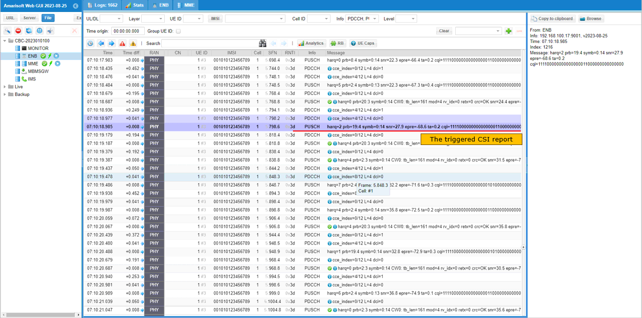
Find the PUSCH that carries CSI report (ri, cqi) that are requestedby the DCI.
Sub Test 2: 2 Trigger - Different
In this sub test, I will show you an example of setting two triggers with different configuration for each trigger.
In cell default configuration, periodic CSI report is disabled by skippingcqi_period and m_ri setting. And Aperiodic CSI report is enabled by configuring ap_cqi_period and ap_cqi_rm. In this test, ap cqi trigger is configured by setting ap_cqi_trigger_list.
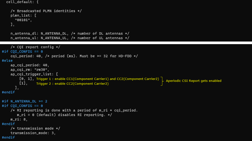
Check out Aperiodic Trigger setting in RRC Connection Reconfiguration. Convert the Hex number of each trigger in aperiodicCSI-Trigger IE into binary and you would figure out the trigger settings for each CC (Component Carrier).
Check if the carrier aggregation is configured as intended by checking out sCellToAddModList IE in RRC Connection Reconfiguration message.
Find a DCI 0 with csi_request set to Non-zero value. This triggers UE to send PUSCH with Aperiodic CQI report. Here it request CSI report configured by Trigger 1. (Check out this noteto figure out how csi_request value is translated to trigger number)
Find the PUSCH that carries CSI report (ri, cqi) that are requestedby the DCI.
Find a DCI 0 with csi_request set to Non-zero value. This triggers UE to send PUSCH with Aperiodic CQI report. Here it request CSI report configured by Trigger 2. (Check out this noteto figure out how csi_request value is translated to trigger number)
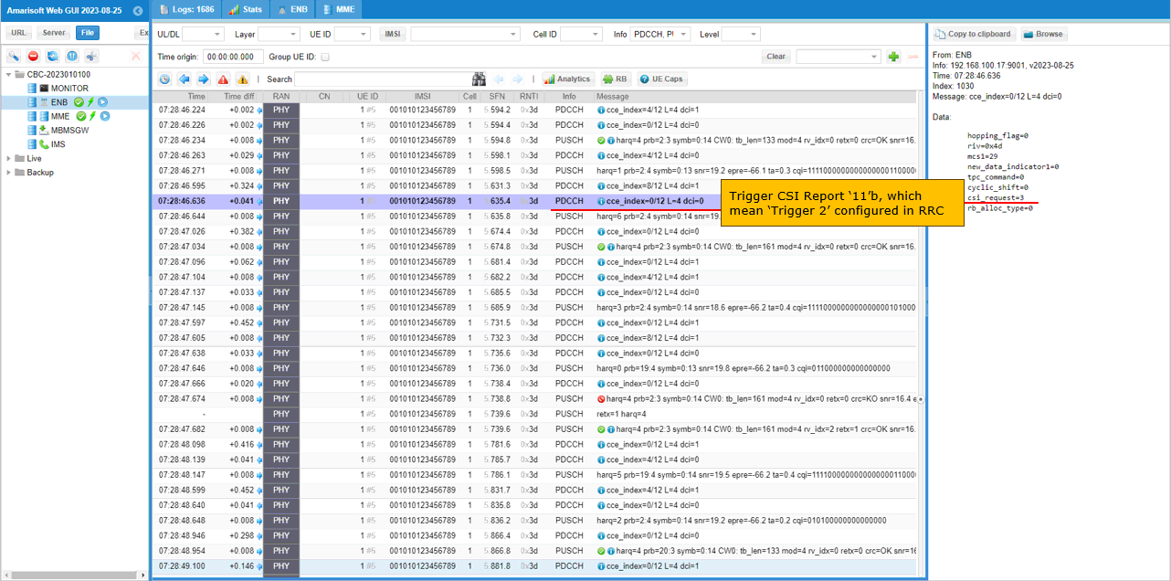
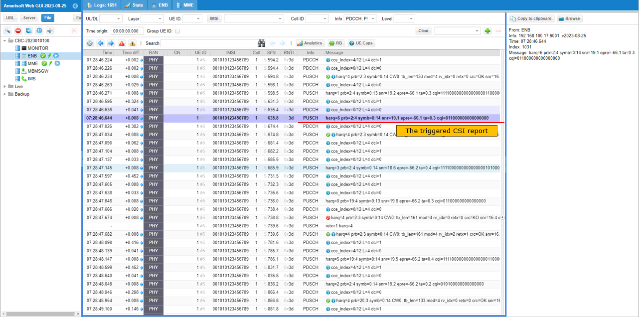
Find the PUSCH that carries CSI report (ri, cqi) that are requestedby the DCI.
Test 3: 6CC CA - with Aperiodic CQI
This test configures 6cells as follows.
- 6 LTE FDD Cells
It performs following procedure
Step 1 : Initial Attach to LTE
Step 2: Establish 6CC CA in LTE with Aperiodic CQI
Configuration
In this testI used the enb-6cc-ap-cqi.cfg which is copied and modified from gnb-nsa.cfg


Followings are the configurations in enb-6cc-ap-cqi.cfg

In this test, 6cells areconfigured in cell_list for carrier aggregation. So each of the cell has scell_list in the configuration that specifies all the other cells as SCC(Secondary Component Carrier).
This is the configuration of the first cell(cell_id 1), so cell_id 2,3,4,5,6 are registered in scell_list
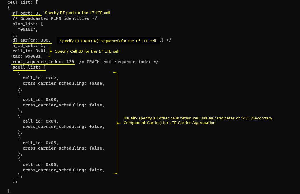
This is the configuration of the seondcell(cell_id 2), so cell_id 1,3,4,5,6 are registered in scell_list
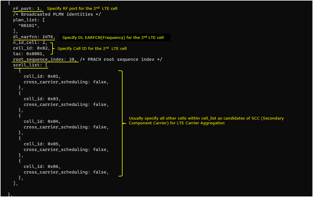
This is the configuration of the 3rdcell(cell_id 3), so cell_id 1,2,4,5,6 are registered in scell_list
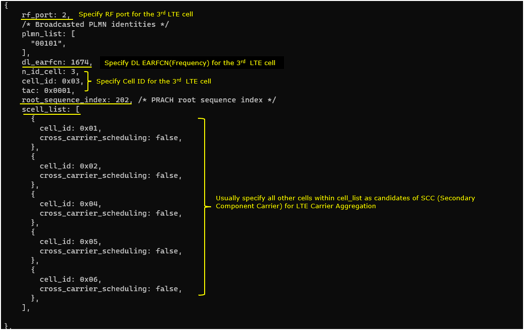
This is the configuration of the 4thcell(cell_id 4), so cell_id 1,2,3,5,6 are registered in scell_list
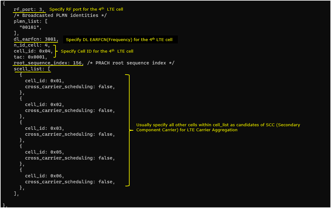
This is the configuration of the 5thcell(cell_id 5), so cell_id 1,2,3,4,6 are registered in scell_list
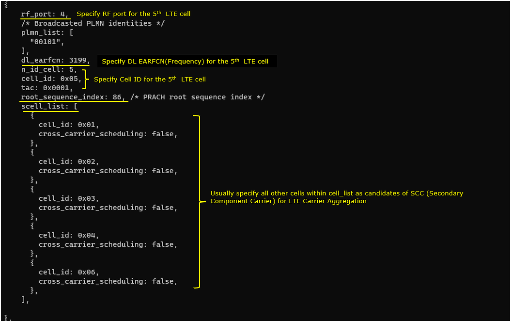
This is the configuration of the 6thcell(cell_id 6), so cell_id 1,2,3,4,5 are registered in scell_list
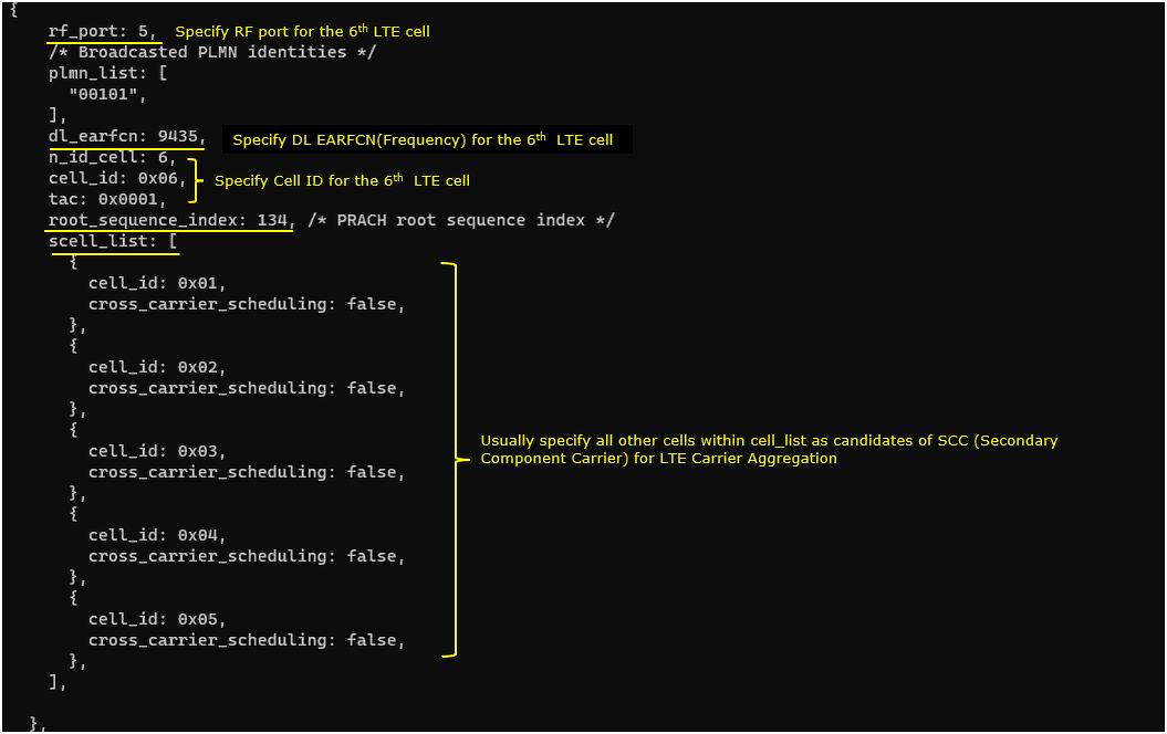
In cell default configuration, periodic CSI report is disabled by skippingcqi_period and m_ri setting. And Aperiodic CSI report is enabled by configuring ap_cqi_period and ap_cqi_rm. In this test, ap cqi trigger is configured by setting ap_cqi_trigger_list. In this test, ap_cqi_trigger_list is not configured which mean that the default configuration will be applied.

Perform the Test
Check out cell configuration with 'cell phy' and 'cell' command and make it sure that all the cells are configured as intended. In this test, makeit sure that all of the 6 cells (carriers) are configured as intended.


NOTE : you may or may notsee the print for C=1 (i.e, the connected state before establising carrier aggregation)because the print shown here is a sampled / averaged. You may take it as success as long as you see the print for C = 6.

Log Analysis
In the log, check out how the aperiodic trigger list are configured in RRC and then how each of the items in the trigger list are used in DCI 0. Convert the Hex number of each trigger in aperiodicCSI-Trigger IE into binary and you would figure out the trigger settings for each CC (Component Carrier).
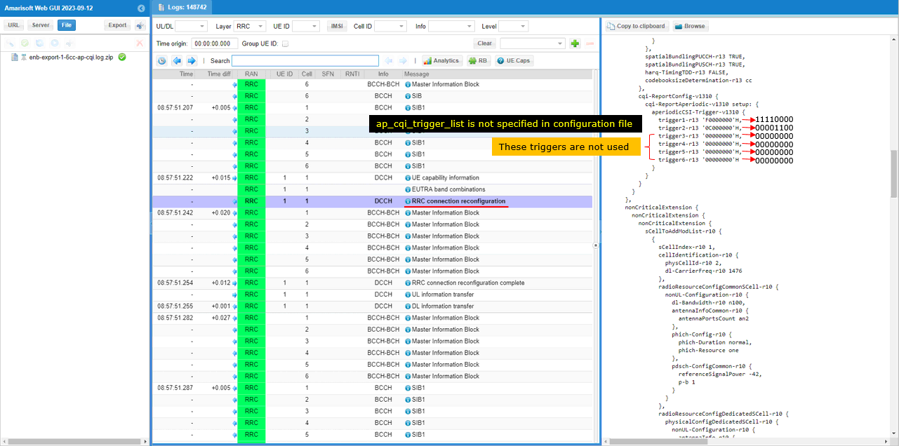
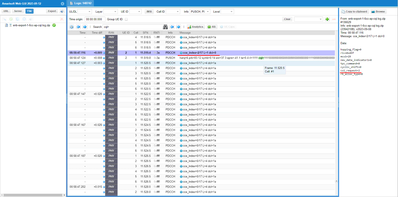
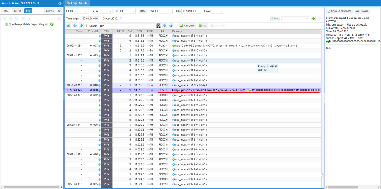
Following logs shows how DCI 0 utilize the configured trigger list. In Amarisoft eNB, it uses each triggers in round-robin manner. (
Find a DCI 0 with csi_request set to Non-zero value. This triggers UE to send PUSCH with Aperiodic CQI report. Here it request CSI report configured by Trigger 1. (Check out FAQto figure out how csi_request value is translated to trigger number)
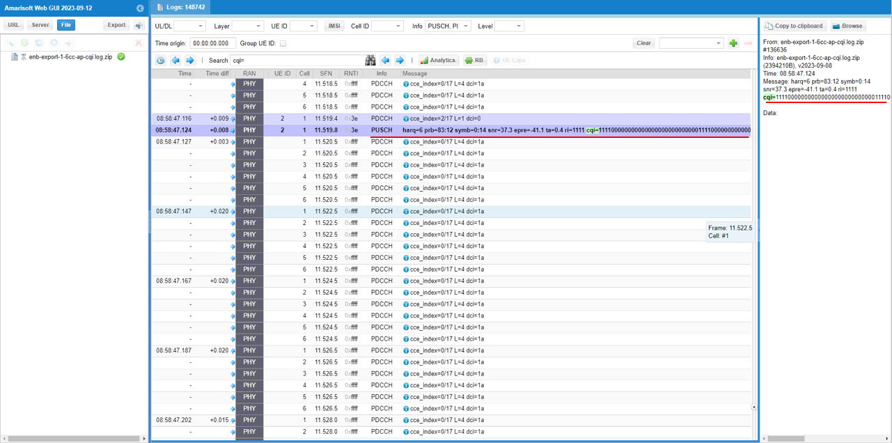
Find the PUSCH that carries CSI report (ri, cqi) that are requestedby the DCI.
Find a DCI 0 with csi_request set to Non-zero value. This triggers UE to send PUSCH with Aperiodic CQI report. Here it request CSI report configured by Trigger 2. (Check out FAQto figure out how csi_request value is translated to trigger number)
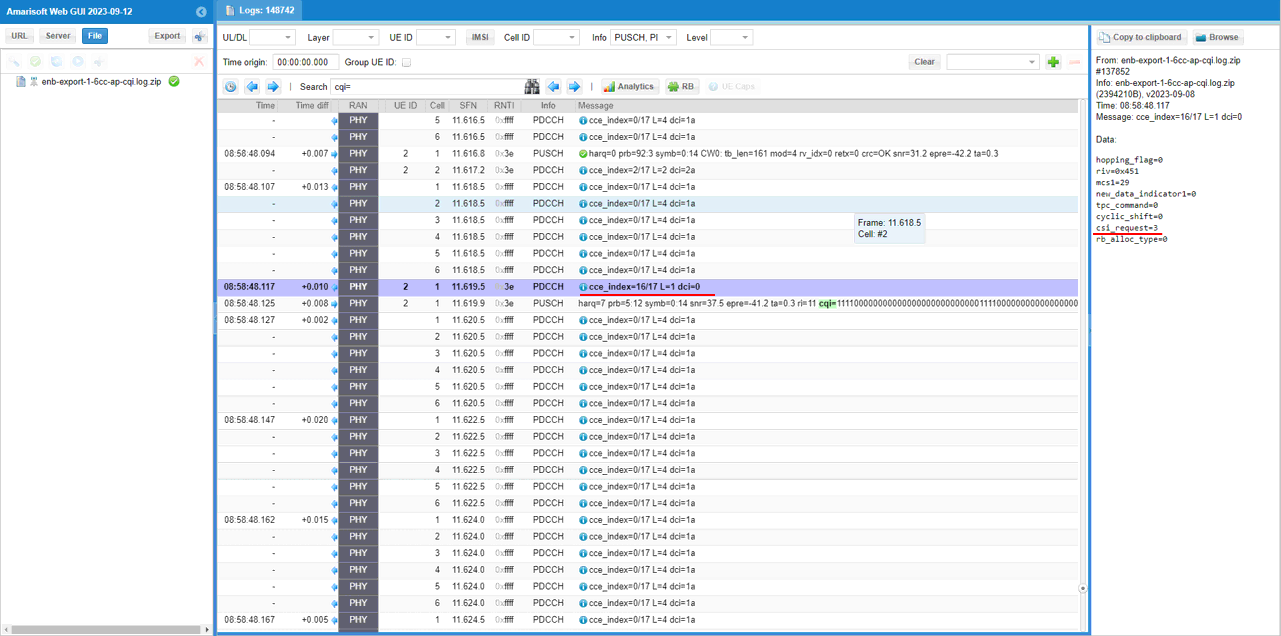
Find the PUSCH that carries CSI report (ri, cqi) that are requestedby the DCI.
Sub Test 1 : 6Trigger - 2 CCs per Trigger
In this sub test, I will show you an example of setting 6 triggers with different configuration for each cells and each triggers has two component carriers enabled.
In this testI used the enb-6cc-ap-cqi_trigger_2perTrigger.cfg which is copied and modified from gnb-nsa.cfg

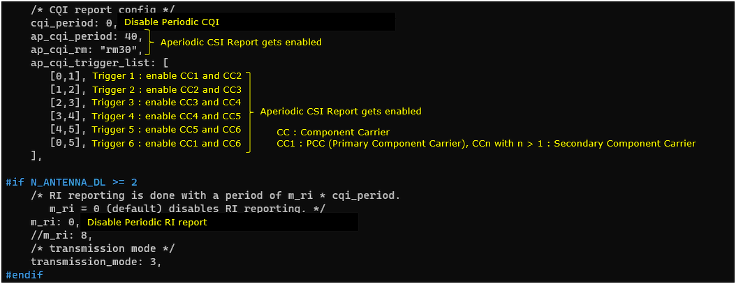
In enb-6cc-ap-cqi_trigger_2perTrigger.cfg, aperiodic triggers are configured as follows.
In cell default configuration, Aperiodic CSI report is enabled by configuring ap_cqi_period and ap_cqi_rm. In this test, ap cqi trigger is configured by setting ap_cqi_trigger_list. Here you see 6 triggers are configured and each of the trigger has two component carries enabled.
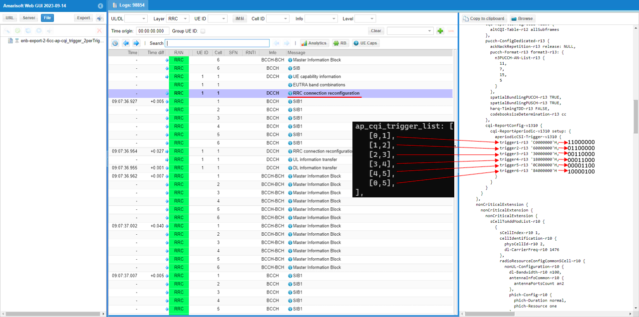
In the log, check out how the aperiodic trigger list are configured in RRC and then how each of the items in the trigger list are used in DCI 0.
Convert the Hex number of each trigger in aperiodicCSI-Trigger IE into binary and you would figure out the trigger settings for each CC (Component Carrier).
Following logs shows how DCI 0 utilize the configured trigger list. In Amarisoft eNB, it uses each triggers in round-robin manner. (
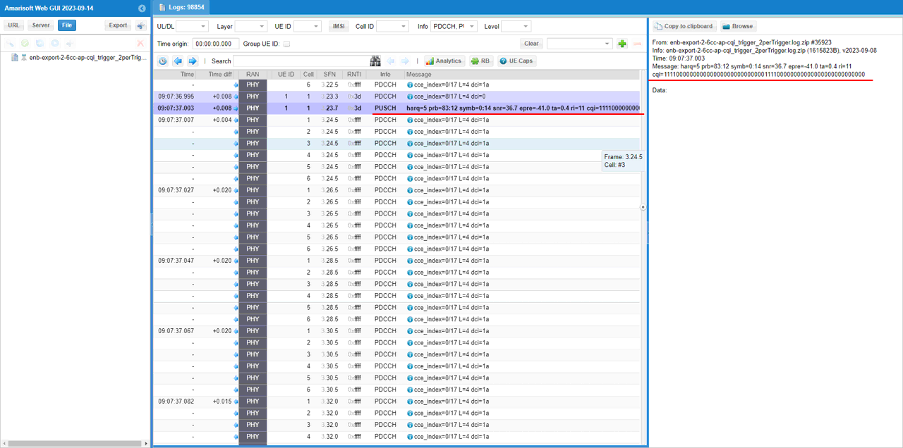
Find a DCI 0 with csi_request set to Non-zero value. This triggers UE to send PUSCH with Aperiodic CQI report. Here it request CSI report configured by Trigger 1. (Check out FAQ to figure out how csi_request value is translated to trigger number)
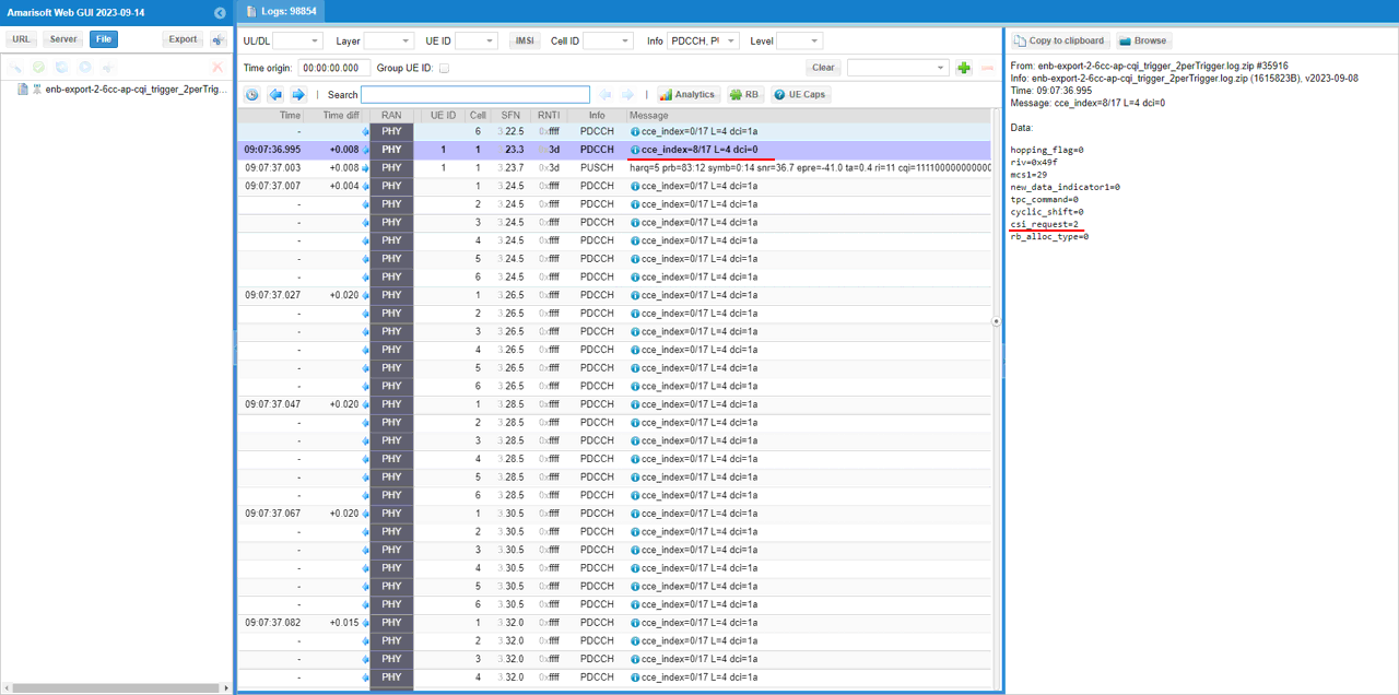
Find the PUSCH that carries CSI report (ri, cqi) that are requestedby the DCI.
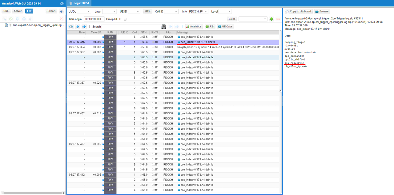
Find a DCI 0 with csi_request set to Non-zero value. This triggers UE to send PUSCH with Aperiodic CQI report. Here it request CSI report configured by Trigger 2. (Check out FAQ to figure out how csi_request value is translated to trigger number)
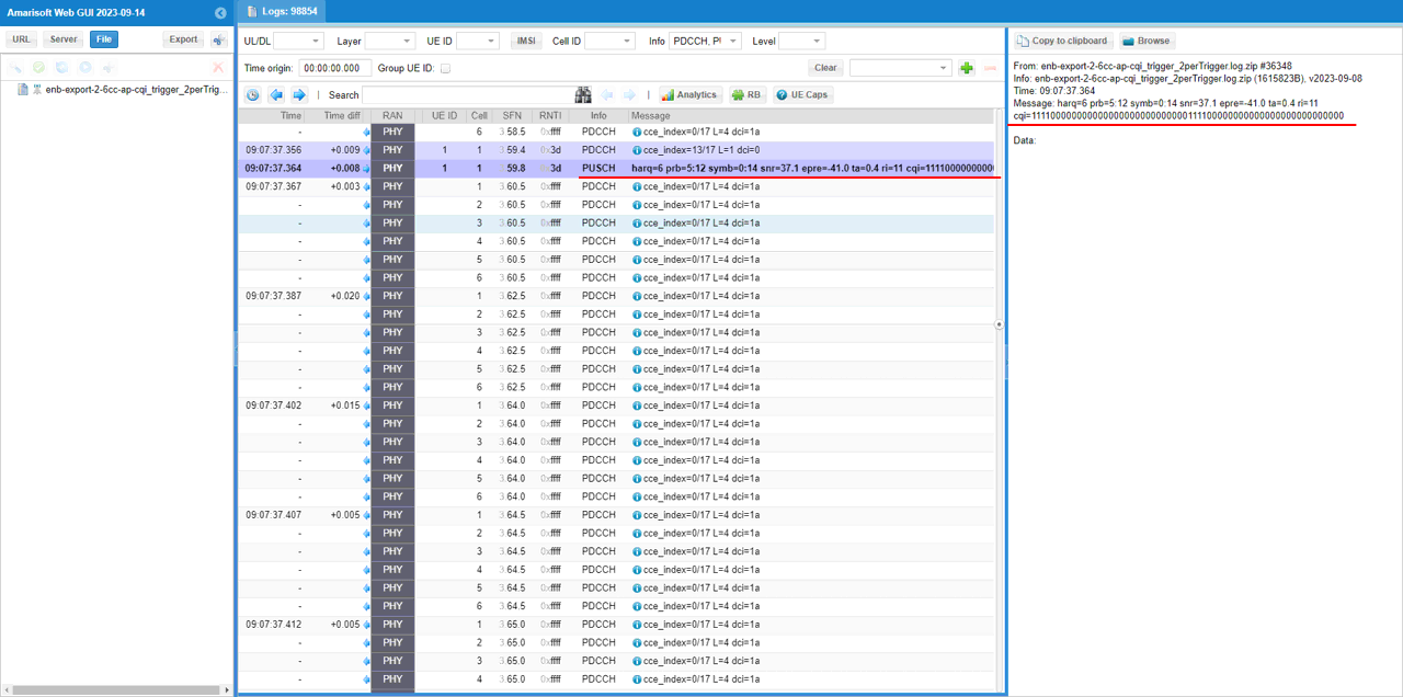
Find the PUSCH that carries CSI report (ri, cqi) that are requestedby the DCI.
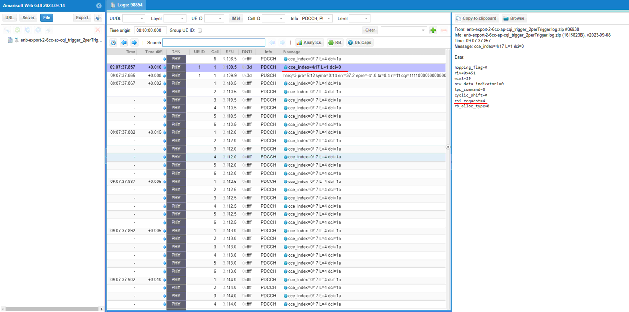
Find a DCI 0 with csi_request set to Non-zero value. This triggers UE to send PUSCH with Aperiodic CQI report. Here it request CSI report configured by Trigger 3. (Check out FAQ to figure out how csi_request value is translated to trigger number)
Find the PUSCH that carries CSI report (ri, cqi) that are requestedby the DCI.
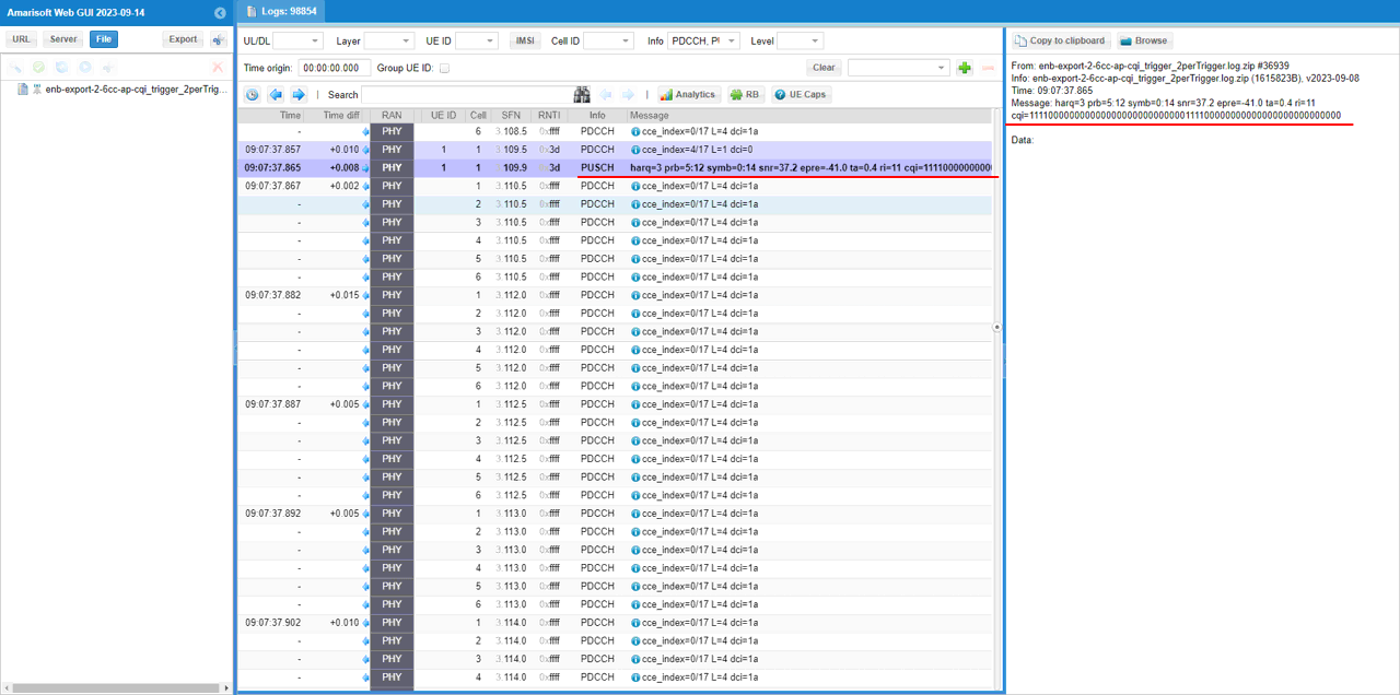
Find a DCI 0 with csi_request set to Non-zero value. This triggers UE to send PUSCH with Aperiodic CQI report. Here it request CSI report configured by Trigger 4. (Check out FAQ to figure out how csi_request value is translated to trigger number)
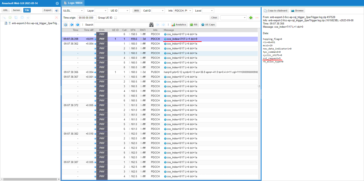
Find the PUSCH that carries CSI report (ri, cqi) that are requestedby the DCI.
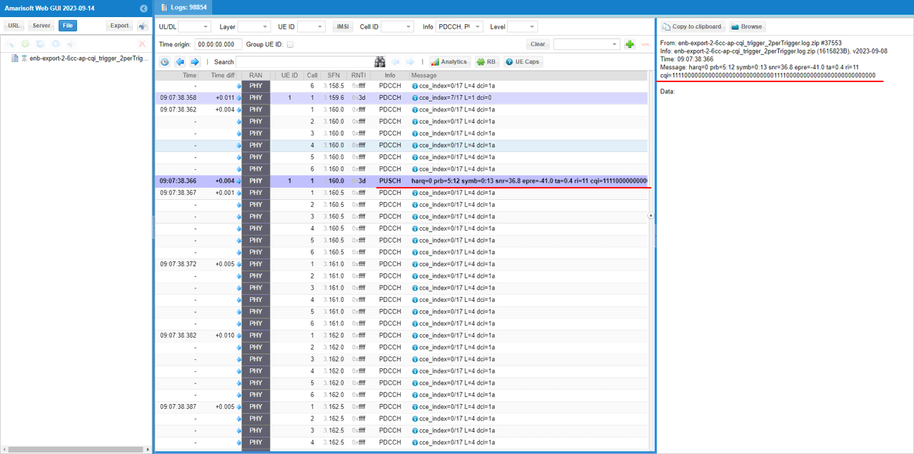
Find a DCI 0 with csi_request set to Non-zero value. This triggers UE to send PUSCH with Aperiodic CQI report. Here it request CSI report configured by Trigger 5. (Check out FAQ to figure out how csi_request value is translated to trigger number)
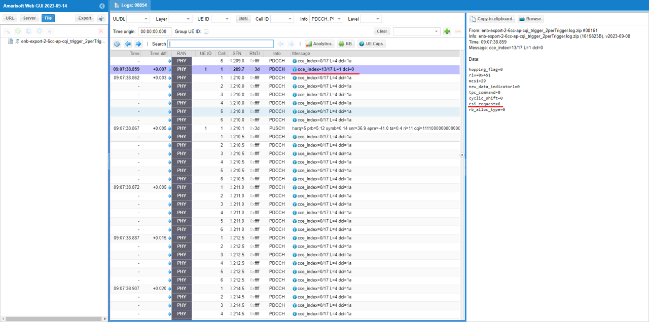
Find the PUSCH that carries CSI report (ri, cqi) that are requestedby the DCI.
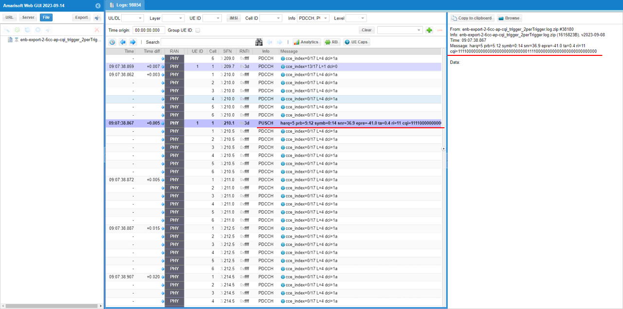
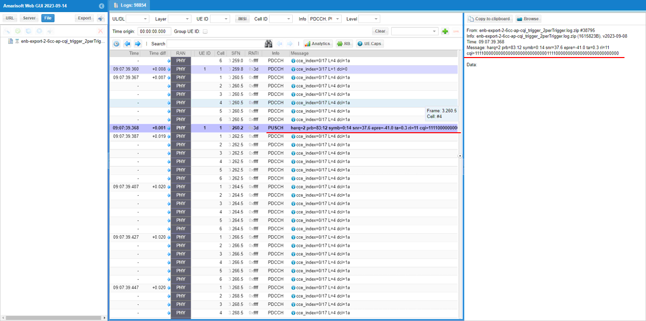
Find a DCI 0 with csi_request set to Non-zero value. This triggers UE to send PUSCH with Aperiodic CQI report. Here it request CSI report configured by Trigger 6. (Check out FAQ to figure out how csi_request value is translated to trigger number)
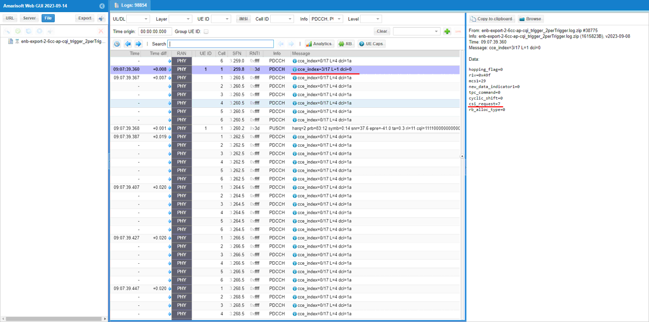
Find the PUSCH that carries CSI report (ri, cqi) that are requestedby the DCI.
Sub Test 2: 6Trigger - ArbitraryCCs per Trigger
In this sub test, I will show you an example of setting 6 triggers with different configuration for each cells and each triggers has different number ofcomponent carriers enabled.
In this testI used the enb-6cc-ap-cqi_trigger_arbTrigger.cfg.cfg which is copied and modified from gnb-nsa.cfg

In enb-6cc-ap-cqi_trigger_arbTrigger.cfg.cfg , aperiodic cqi is configured as follows.
In cell default configuration, Aperiodic CSI report is enabled by configuring ap_cqi_period and ap_cqi_rm. In this test, ap cqi trigger is configured by setting ap_cqi_trigger_list. Here you see 6 triggers are configured and each of the trigger has different number ofcomponent carries enabled.
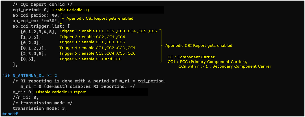
In the log, check out how the aperiodic trigger list are configured in RRC and then how each of the items in the trigger list are used in DCI 0.
Convert the Hex number of each trigger in aperiodicCSI-Trigger IE into binary and you would figure out the trigger settings for each CC (Component Carrier).
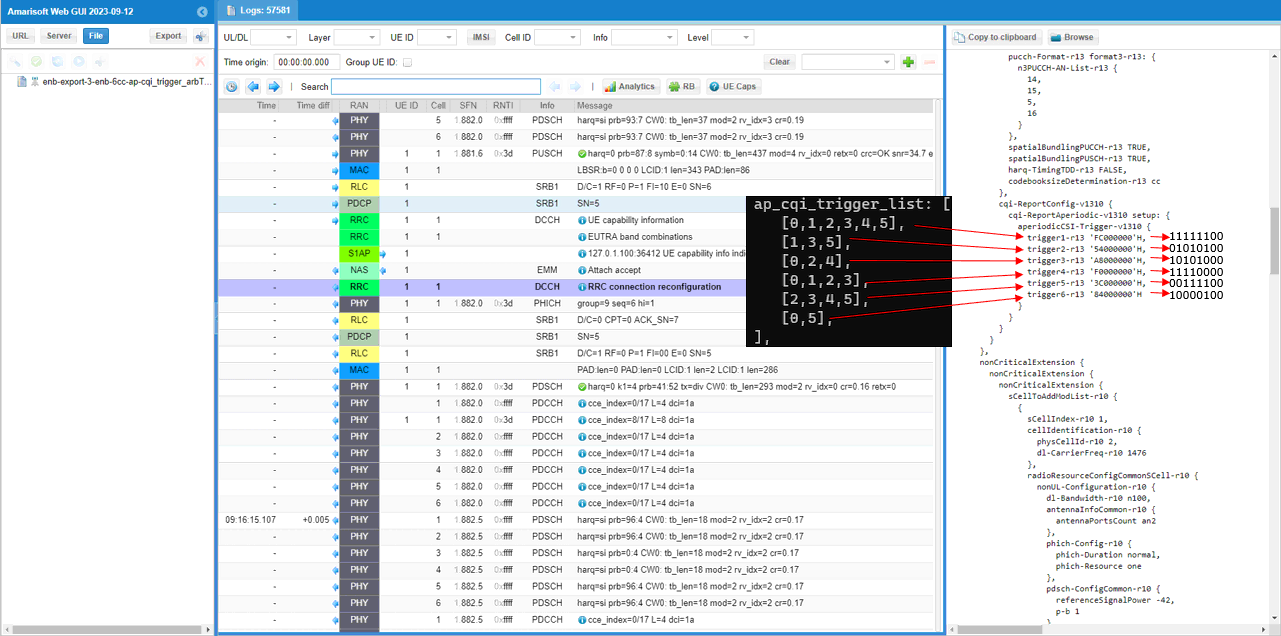
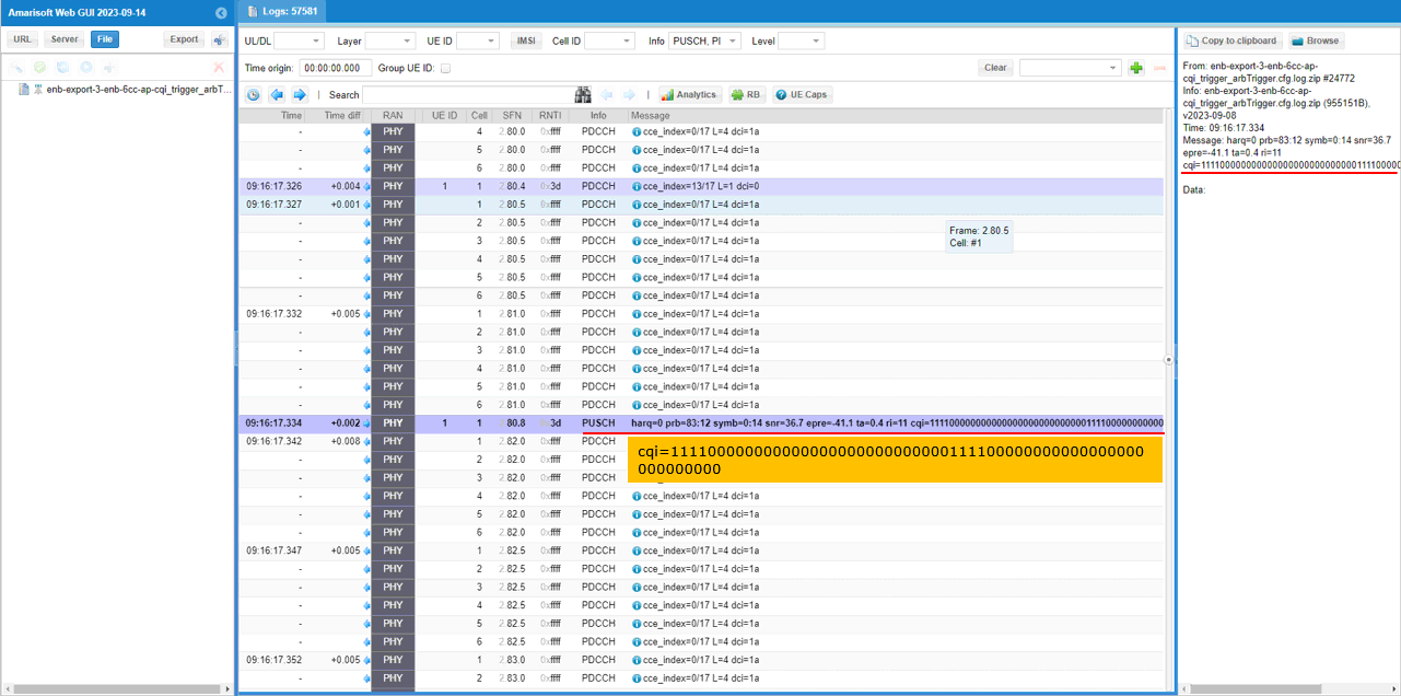
Following logs shows how DCI 0 utilize the configured trigger list. In Amarisoft eNB, it uses each triggers in round-robin manner. (
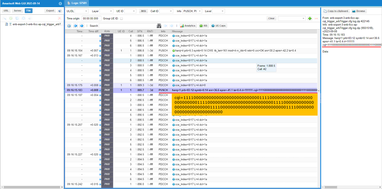
This triggers UE to send PUSCH with Aperiodic CQI report. Here it request CSI report configured by Trigger 1. (Check out FAQ to figure out how csi_request value is translated to trigger number)
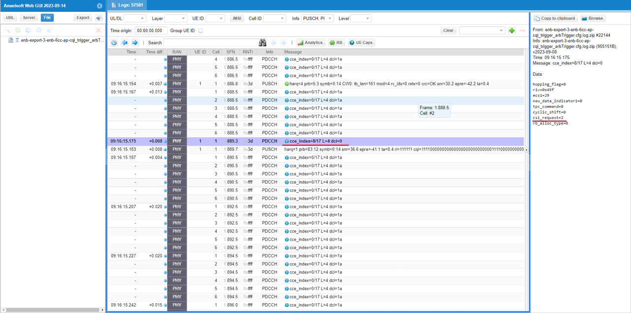
Find the PUSCH that carries CSI report (ri, cqi) that are requestedby the DCI.
Find a DCI 0 with csi_request set to Non-zero value. This triggers UE to send PUSCH with Aperiodic CQI report. Here it request CSI report configured by Trigger 2. (Check out FAQ to figure out how csi_request value is translated to trigger number)
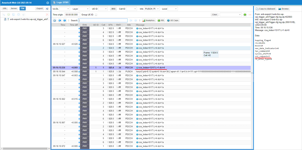
Find the PUSCH that carries CSI report (ri, cqi) that are requestedby the DCI.
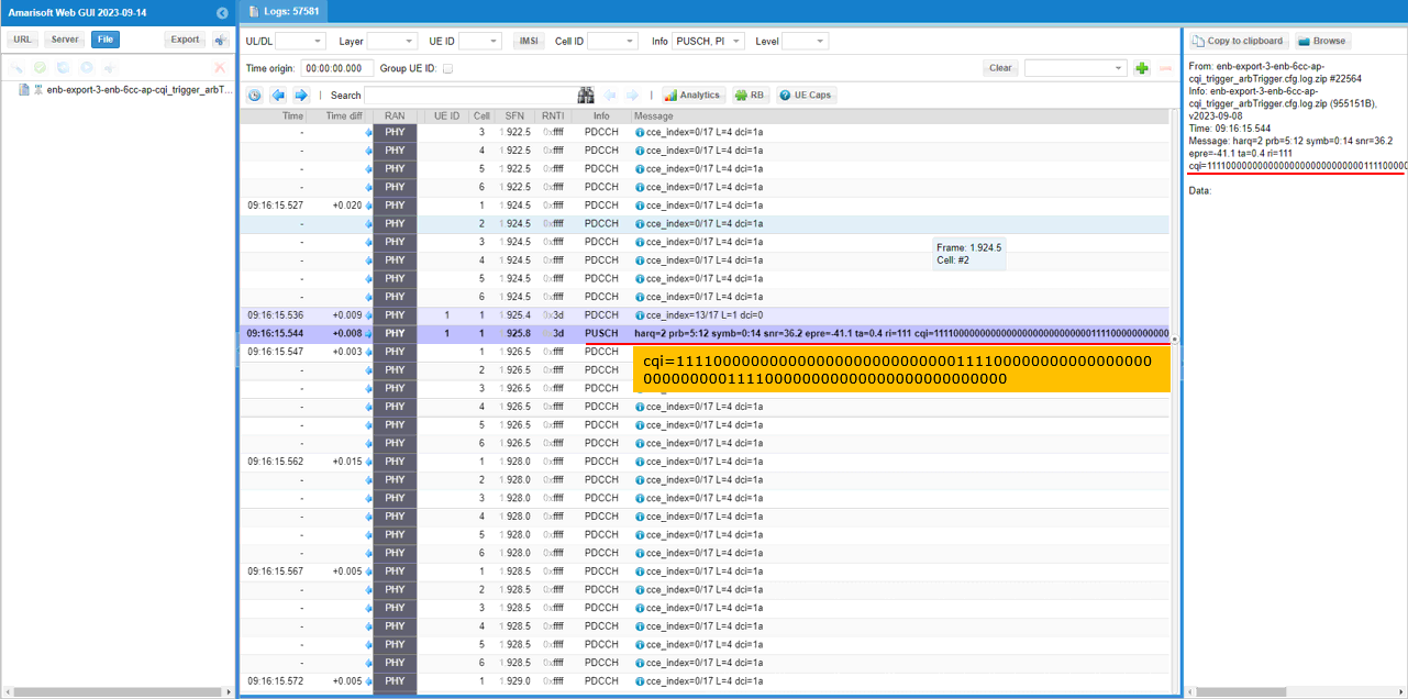
Find a DCI 0 with csi_request set to Non-zero value. This triggers UE to send PUSCH with Aperiodic CQI report. Here it request CSI report configured by Trigger 3. (Check out FAQ to figure out how csi_request value is translated to trigger number)
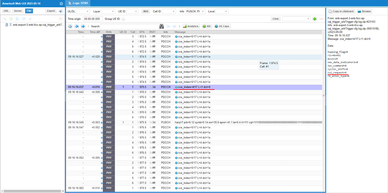
Find the PUSCH that carries CSI report (ri, cqi) that are requestedby the DCI.
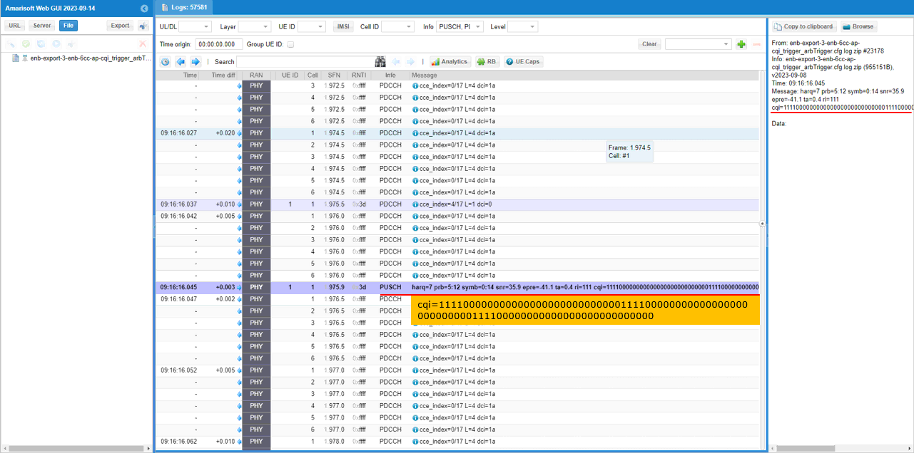
Find a DCI 0 with csi_request set to Non-zero value. This triggers UE to send PUSCH with Aperiodic CQI report. Here it request CSI report configured by Trigger 4. (Check out FAQ to figure out how csi_request value is translated to trigger number)
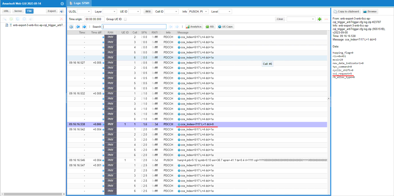
Find the PUSCH that carries CSI report (ri, cqi) that are requestedby the DCI.
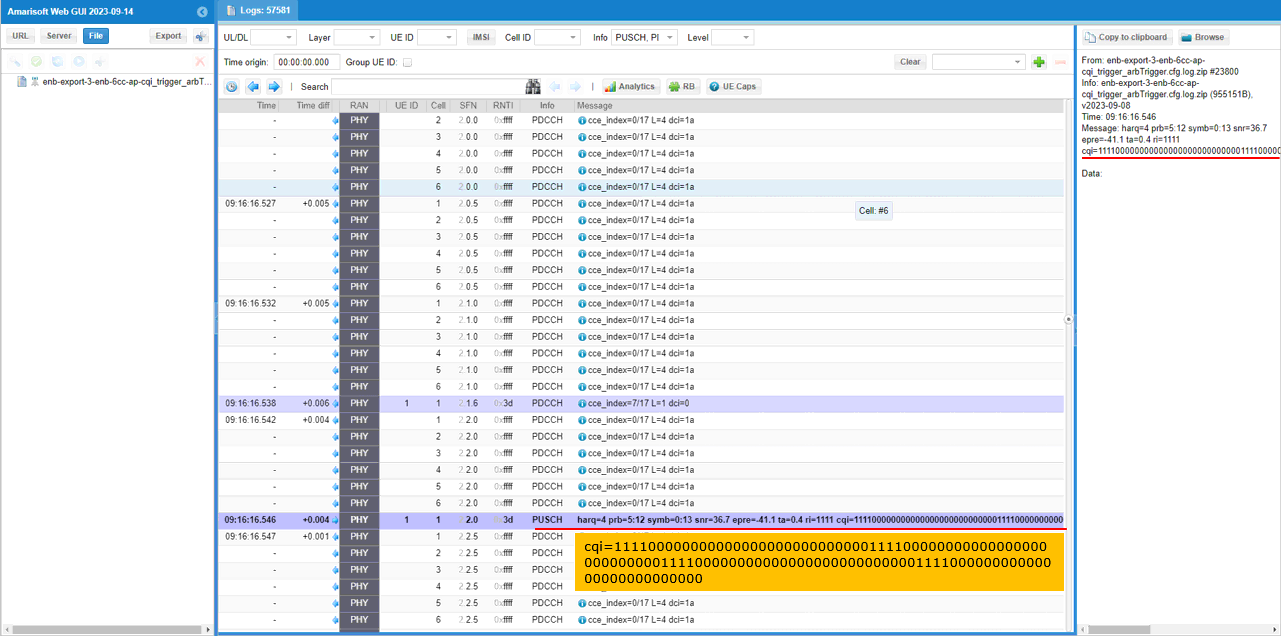
Find a DCI 0 with csi_request set to Non-zero value. This triggers UE to send PUSCH with Aperiodic CQI report. Here it request CSI report configured by Trigger 5. (Check out FAQ to figure out how csi_request value is translated to trigger number)
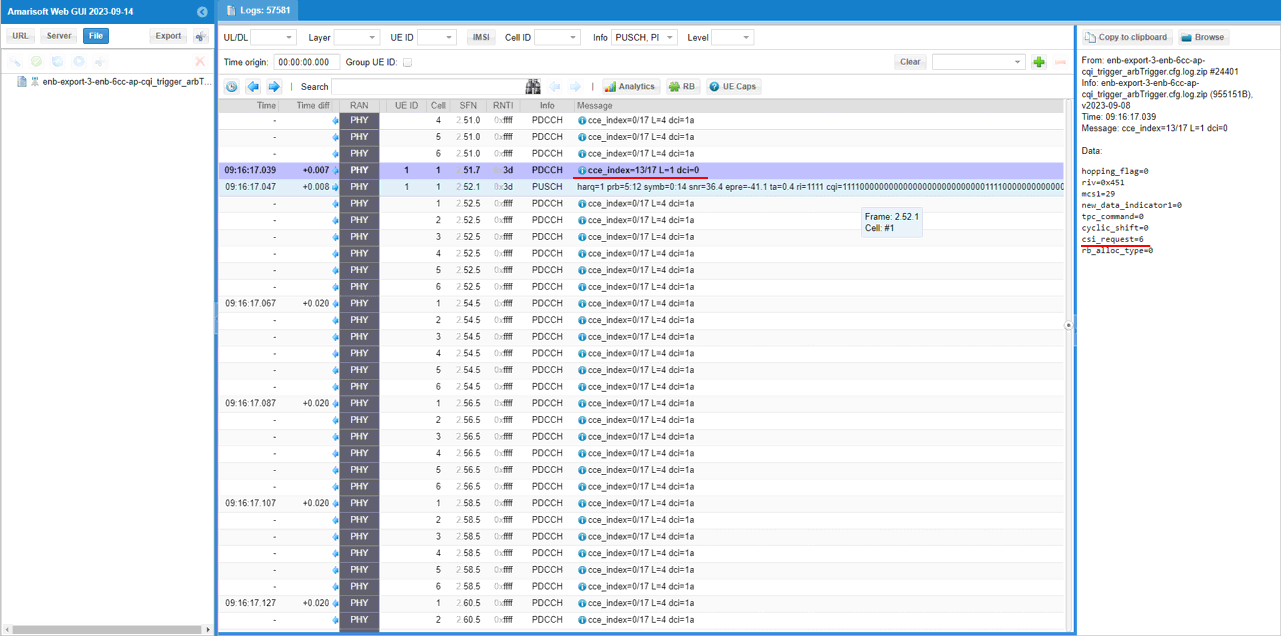
Find the PUSCH that carries CSI report (ri, cqi) that are requestedby the DCI.
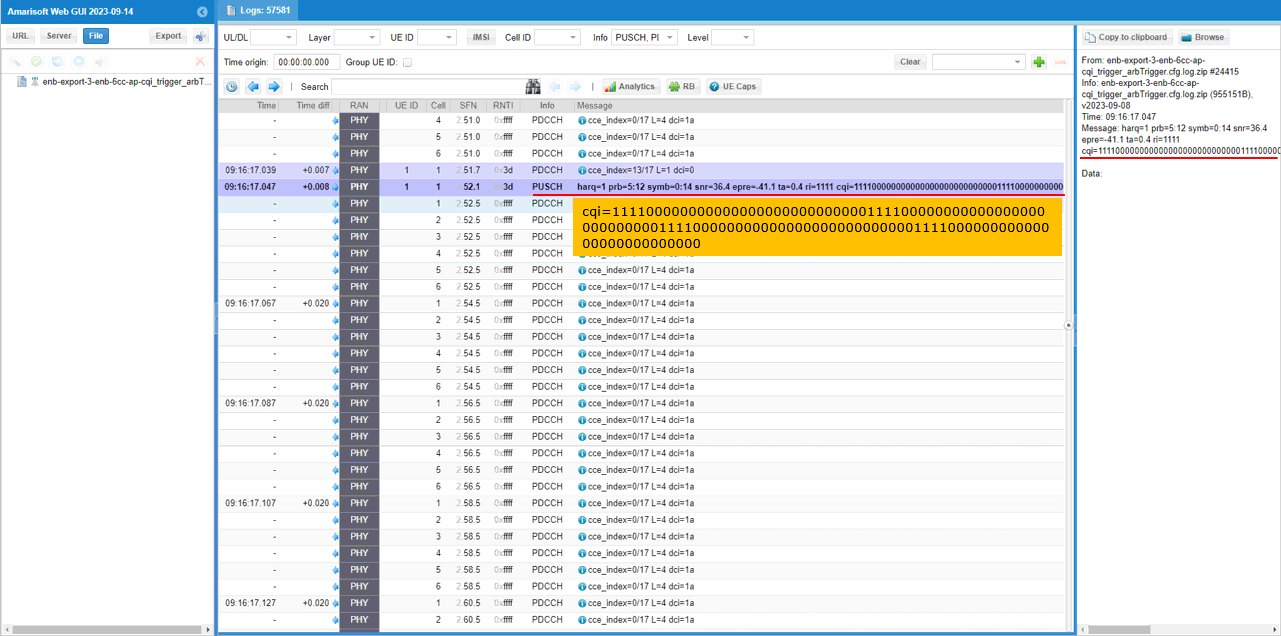
Find a DCI 0 with csi_request set to Non-zero value. This triggers UE to send PUSCH with Aperiodic CQI report. Here it request CSI report configured by Trigger 6. (Check out FAQ to figure out how csi_request value is translated to trigger number)
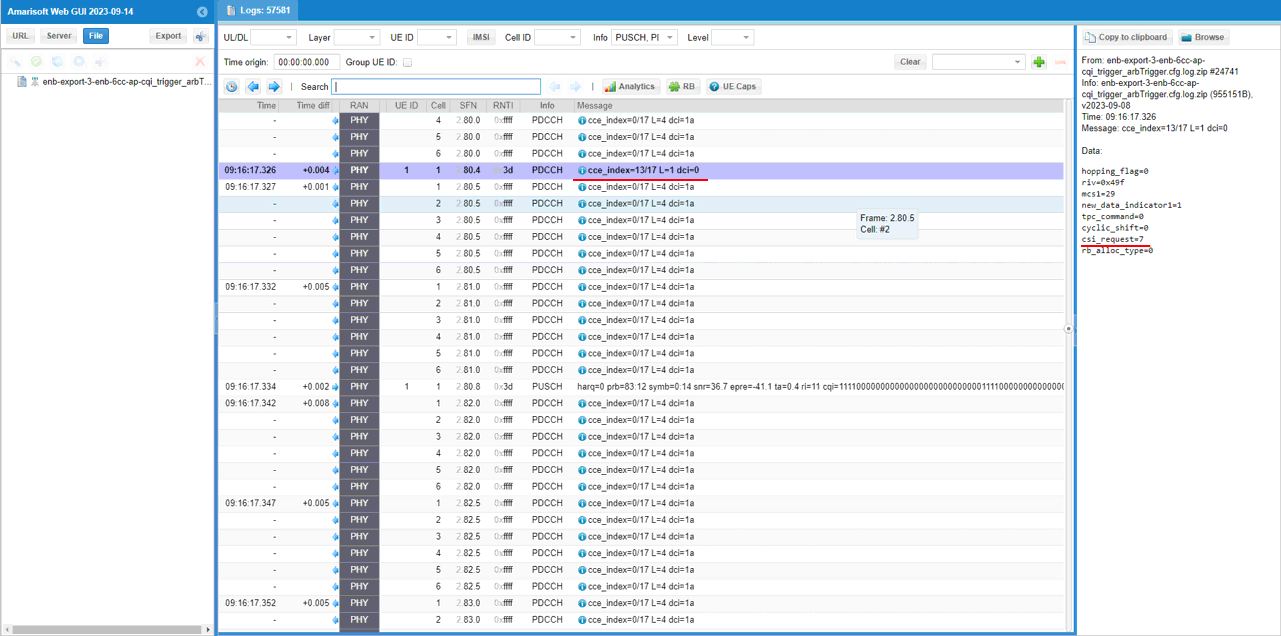
Find the PUSCH that carries CSI report (ri, cqi) that are requestedby the DCI.
RRC / NAS Signaling
RrcConnectionReconfiguration
: This is the RrcConnectionReconfigurationmessage sent by eNB to configure Aperiodic Trigger (
{
message c1: rrcConnectionReconfiguration: {
rrc-TransactionIdentifier 0,
criticalExtensions c1: rrcConnectionReconfiguration-r8: {
dedicatedInfoNASList {
'270FDC9A170107420......08'H
},
radioResourceConfigDedicated {
srb-ToAddModList {
{
srb-Identity 2,
rlc-Config explicitValue: am: {
ul-AM-RLC {
t-PollRetransmit ms60,
pollPDU pInfinity,
pollByte kBinfinity,
maxRetxThreshold t32
},
dl-AM-RLC {
t-Reordering ms45,
t-StatusProhibit ms0
}
},
logicalChannelConfig defaultValue: NULL
}
},
drb-ToAddModList {
{
eps-BearerIdentity 5,
drb-Identity 1,
pdcp-Config {
discardTimer infinity,
rlc-AM {
statusReportRequired TRUE
},
headerCompression notUsed: NULL
},
rlc-Config am: {
ul-AM-RLC {
t-PollRetransmit ms80,
pollPDU p64,
pollByte kB125,
maxRetxThreshold t32
},
dl-AM-RLC {
t-Reordering ms35,
t-StatusProhibit ms10
}
},
logicalChannelIdentity 3,
logicalChannelConfig {
ul-SpecificParameters {
priority 15,
prioritisedBitRate kBps8,
bucketSizeDuration ms100,
logicalChannelGroup 3
}
}
}
},
physicalConfigDedicated {
cqi-ReportConfig-r10 {
cqi-ReportAperiodic-r10 setup: {
cqi-ReportModeAperiodic-r10 rm30,
aperiodicCSI-Trigger-r10 {
trigger1-r10 'C0'H,
trigger2-r10 '40'H
}
},
nomPDSCH-RS-EPRE-Offset 0,
cqi-ReportPeriodic-r10 release: NULL
},
pucch-ConfigDedicated-v1020 {
pucch-Format-r10 channelSelection-r10: {
n1PUCCH-AN-CS-r10 setup: {
n1PUCCH-AN-CS-List-r10 {
{
0,
1,
2,
3
}
}
}
}
},
cqi-ReportConfigPCell-v1250 {
altCQI-Table-r12 allSubframes
}
}
},
nonCriticalExtension {
nonCriticalExtension {
nonCriticalExtension {
sCellToAddModList-r10 {
{
sCellIndex-r10 1,
cellIdentification-r10 {
physCellId-r10 2,
dl-CarrierFreq-r10 1575
},
radioResourceConfigCommonSCell-r10 {
nonUL-Configuration-r10 {
dl-Bandwidth-r10 n25,
antennaInfoCommon-r10 {
antennaPortsCount an1
},
phich-Config-r10 {
phich-Duration normal,
phich-Resource one
},
pdsch-ConfigCommon-r10 {
referenceSignalPower -29,
p-b 0
}
}
},
radioResourceConfigDedicatedSCell-r10 {
physicalConfigDedicatedSCell-r10 {
nonUL-Configuration-r10 {
antennaInfo-r10 {
transmissionMode-r10 tm1,
ue-TransmitAntennaSelection release: NULL
},
crossCarrierSchedulingConfig-r10 {
schedulingCellInfo-r10 own-r10: {
cif-Presence-r10 FALSE
}
},
pdsch-ConfigDedicated-r10 {
p-a dB0
}
},
ul-Configuration-r10 {
cqi-ReportConfigSCell-r10 {
cqi-ReportModeAperiodic-r10 rm30,
nomPDSCH-RS-EPRE-Offset-r10 0,
cqi-ReportPeriodicSCell-r10 release: NULL
}
},
cqi-ReportConfigSCell-v1250 {
altCQI-Table-r12 allSubframes
}
}
}
}
}
}
}
}
}
}
}
FAQ
[Q1] How can I interpret the ap_cqi_trigger_list[] in the configuration file and how it gets translated to RRC Configuration ?
[A1] Explained below.
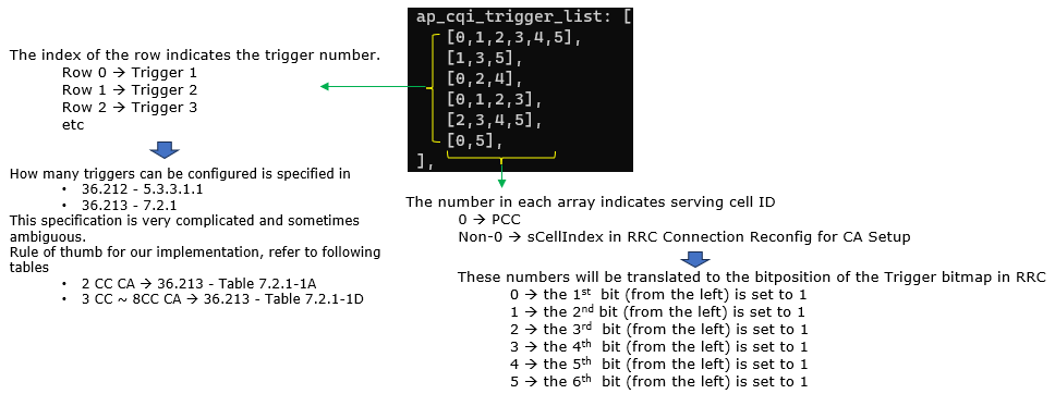
This configuration is translated to RRC configuration as follows.

[Q2] How each of the trigger is selected by each triggering DCI 0 ?
[A2] The trigger is selected in round robin manner among the triggers which are NOT all 0.
hopping_flag=0
riv=0x451
mcs1=29
new_data_indicator1=0
tpc_command=0
cyclic_shift=0
rb_alloc_type=0
In case of 6CC as an example, the maning of csi_request value indicates differently depending on which specific 7.2.1-XX table is applied. The table selection algorithm is described in 36.213-7.2.1 which is very confusing. For the current Amarisoft configuration, you may assume that 7.2.1-1D is used. Given that, you can interpret the value of csi_request as follows :
