Testing Data Throughput version 2026-04-02*This document is based on the latest test release.
Features may not be present in your current installed software. You may check their availability in your release documentation.
If you require an up to date release, ask for it in a ticket.
Features may not be present in your current installed software. You may check their availability in your release documentation.
If you require an up to date release, ask for it in a ticket.
Table of Contents
1 Introduction
This application note explains the procedure for testing data throughput using Amarisoft eNodeB and EPC (Enhanced Packet Core). We will focus on testing DL (downlink), UL (uplink) and bidirectional data transfers. We will also present recommended applications to be used with UDP and TCP as well as optimal TCP settings to achieve maximum throughput. Some configuration changes may apply if you use Amarisoft eNodeB with a third party EPC or if you use Amarisoft EPC with an external eNodeB. The verification steps could also be different depending on the commands available on third party EPC and eNodeB.
Following section gives you a brief background. Next chapter gives you some hints on the configuration and tools to be used as well as a step by step procedure to execute your throughput tests. The last two chapters focus on logging and troubleshooting to ease the debug process.
1.1 Background
LTE is providing a very large increase in data transmission capacity of mobile networks. Advanced technologies such as MIMO (Multi-Input Multiple-Output) and CA (Carrier Aggregation) have yet enabled higher data rates.
The 3GPP TR (Technical Report) 37.901 document specifies application layer UE data throughput performance testing for both HSPA and LTE networks. It is proposed to test with both TCP and UDP as measurements utilizing each transport protocol are relevant.
- TCP
- - TCP is mostly used in applications that need reliable data transfers.
- - TCP throughput is sensitive to the end-to-end delay and packet loss.
- - Bi-directional TCP tests in asymmetric data rate links would cause the downlink speed to be limited by uplink speed. For TCP data transfers in one direction, the TCP ACKs are transmitted in the other direction, therefore delay in receiving TCP ACK in one direction negatively impacts the throughput in the other direction.
- UDP
- - Most multimedia and real-time applications use UDP protocol.
- - The performance of UDP based data transfer, unlike TCP based transfer, is Operating System agnostic and is not sensitive to end-to-end delay.
- - UDP Data Transfer in one direction is not dependent on the other direction, unlike with TCP.
There are several factors that could effectively affect the data throughput:
- UE category,
- Network configuration: cell bandwidth (variable from 1.4 to 20 MHz), transmission mode and CA configuration,
- Number of users in the cell,
- Signal level: channel and fading conditions, link loss, noise from other UEs, interference from other base stations or radio access technologies,
- Application level configuration.
In the following chapter, we will go through all the above items giving recommendation on how to achieve the best throughput.
2 Throughput Tests
2.1 UE Category
First thing to check before starting your throughput tests is the UE category. The UE category indicates the maximum theoretical UL and DL data rates that the UE can achieve. It could be found in the RRC message UE Capability Information.
The following example is an extract of OnePlus3 capability information.
UE Capability Information
{
  message c1: ueCapabilityInformation: {
    rrc-TransactionIdentifier 0,
    criticalExtensions c1: ueCapabilityInformation-r8: {
      ue-CapabilityRAT-ContainerList {
        {
          rat-Type eutra,
          ueCapabilityRAT-Container {
            accessStratumRelease rel11,
            ue-Category 4,
            ...
            },
            nonCriticalExtension {
              ...
                nonCriticalExtension {
                  ue-Category-v1020 6,
                  ...
                  rf-Parameters-v1020 {
                    supportedBandCombination-r10 {
                      ...
                      {
                        {
                          bandEUTRA-r10 7,
                          bandParametersUL-r10 {
                            {
                              ca-BandwidthClassUL-r10 a
                            }
                          },
                          bandParametersDL-r10 {
                            {
                              ca-BandwidthClassDL-r10 a,
                              supportedMIMO-CapabilityDL-r10 twoLayers
                            }
                          }
                        }
                        {
                          bandEUTRA-r10 3,
                          bandParametersDL-r10 {
                           {
                             ca-BandwidthClassDL-r10 a,
                             supportedMIMO-CapabilityDL-r10 twoLayers
                           }
                          }
                        }
                      },
                      ...
                    }
                  },
                  ...
                  nonCriticalExtension {
                    ...
                    nonCriticalExtension {
                      nonCriticalExtension {
                        ...
                        nonCriticalExtension {
                          nonCriticalExtension {
                            ...
                            nonCriticalExtension {
                              nonCriticalExtension {
                                rf-Parameters-v1250 {
                                  supportedBandListEUTRA-v1250 {
                                    ...
                                    {
                                      dl-256QAM-r12 supported,
                                      ul-64QAM-r12 supported
                                    }
                                  }
                                },
                                ue-CategoryDL-r12 13,
                                ue-CategoryUL-r12 5
                              }
                              ...
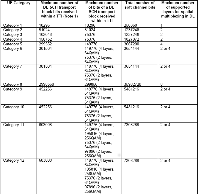
The field ue-Category of the UE Capability Information defines a combined uplink and downlink capability. The parameters set by the UE Category are defined in 3GPP TS 36.306. The following table depicts the DL physical layer parameters set by ue-Category.
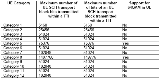
The following table depicts the UL physical layer parameters set by ue-Category.
As can be seen in the above UE Capability Information message, the OnePlus3 phone declares to be a category 4 and category 6 device. LTE category 6 has only been added to the specification in release 10. As such, a category 6 device is required to report category 4 as well to be backward compatible with release 8 networks.
As a category 4 device, OnePlus3 is capable to support 150 Mbps in DL and 51 Mbps in UL at physical layer. DL throughput is achieved by using two layers spatial multiplexing and 64QAM modulation. As a category 6 device, OnePlus 3 device should achieve a max theoretical throughput of 301 Mbps in DL and 51 Mbps in DL.
The above ue-category tables only indicate the maximum theoretical throughput, but do not give any detail about the specific MIMO or CA configuration. As an example, a throughput of 301 Mbps in DL could be achieved either by combining two 20 MHZ carriers with each carrier supporting two layers spacial multiplexing or by using four layers spacial multiplexing in a single cell.
The most common case among commercial devices is to aggregate two carrier components of 20 MHZ each to achieve 301 Mbps in category 6. Looking back at OnePlus3 capabilities, we can see that the device is supporting carrier aggregation with two carrier components as seen in IE (Information Element) supportedBandCombination-r10. Its supported MIMO capability in DL in each carrier is two layers.
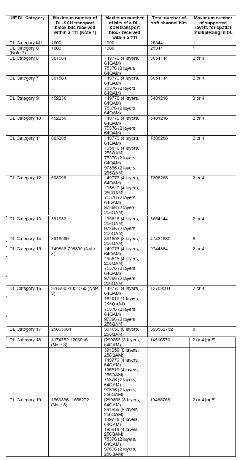
Starting from Release 12, a UE can indicate its DL category and UL category separately. The following table depicts the physical layer parameter values corresponding to ue-CategoryDL.
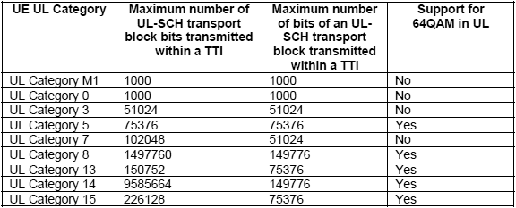
The following table depicts the physical layer parameter values corresponding to ue-CategoryUL.
OnePlus3 device is also declaring to be category 13 in DL with 391 Mbps in DL. This category requires support of 256QAM in DL allowing transport blocks to carry up to 97896 bits. As can be seen in OnePlus3 UE Capability Information message, it declares to support 256QAM modulation on top of CA with two carriers and two layers spacial multiplexing in DL. Combining all these features, the OnePlus3 device is able to receive a maximum of 4 transport blocks with 256QAM modulation in a TTI, ie. two transport blocks per TTI per carrier. This will give a DL rate of 4 x 97896 x 1000 = 391 Mbps.
Oneplus3 device is also declaring to be category 5 in UL with 75 Mbps in UL. This category requires support of 64QAM in UL allowing transport blocks to carry up to 75376 bits.
Once the device maximum supported data rate in UL and DL is figured out, next step would be to configure Amarisoft network. This is discussed in the next section.
It would be worthy to note that these throughput numbers are theoretical. All DL/UL TTIs do not carry only user data, there are also a certain portion of overhead due to control part such as SIBs, Signaling as well as user plane protocol headers. So real throughput you get will be less than the one listed in the above tables.
2.2 Network Configuration
The eNodeB configuration plays an important role to achieve best performance. Once the UE category is deduced, it is important to start eNodeB with the right configuration file. The following parameters are important to achieve maximum throughput.
- Cell bandwidth: The cell bandwidth has a direct impact on the maximum capacity of the cell. The higher the cell bandwidth, the higher will be the maximum throughput. In Amarisoft solution, the cell bandwidth is configured with the
n_rb_dlparameter giving the number of resource blocks. This parameter is available in eNodeB configuration file.- - Use
n_rb_dl = 6, 15, 25, 50, 75, 100for the bandwidths1.4, 3, 5, 10, 15, 20 MHz. - - To ease the bandwidth change, the enb.cfg configuration file has a define at the top named N_RB_DL that can be set to 6, 15, 25, 50, 75, 100.
- - In order to achieve the highest data rate within a cell, the cell bandwidth parameter should be set to 20 MHZ.
- - Use
- Transmission mode: In the downlink, LTE uses technologies such as MIMO to achieve high data rates. In LTE jargon, this is called transmission mode. It is configured with the
transmission_modeandtransmission_mode_optparameters in the eNodeB configuration file.- - For two layers spacial multiplexing,
transmission_modeparameter could be set to 3 or 4. - - Transmission modes 3 and 4 need rank indicator reporting for proper operation.
m_riparameter configures the periodicity of CQI/PMI reports and it should be set to a non-zero value. - - A typical example to enable 2x2 MIMO in DL is the file enb.cfg which is suitable for a cat 4 device. To use it in 2x2 DL MIMO 20MHz configuration, edit the file and change N_RB_DL to 100 and N_ANTENNA_DL to 2.
- - For two layers spacial multiplexing,
- Carrier aggregation: there are a lot of parameters to set in this case. A typical example is provided in file enb-2cc.cfg for a category 6 device. This file enables two cells with 5 MHZ bandwidth and in bands 3 and 7. To use it in 2x2 DL MIMO 20MHz configuration, edit the file and change N_RB_DL to 100 and N_ANTENNA_DL to 2.
- Number of resource blocks allocated to control: Indeed, not all the resource blocks within a cell could be allocated to user data:
- - In DL, typically some resource blocks should be dedicated to SIBs, PDCCH, etc. Amarisoft eNodeB allows you to specify the number of OFDM symbols for PDCCH. This is controlled with the
n_symb_cchparameter in eNodeB configuration file. A value of 0 means that eNodeB will automatically adjust the number of OFDM symbols. A value of 1 is the minimum that you can set for this parameter. The more UEs you have in your cell, the more OFDM symbols are required for PDCCH. So a value of 1 is useful for capacity testing to increase the number of resources blocks used for user data but in real life, this value should be set to 0 or > 1. - - in UL, some resource blocks are allocated to CQI reporting and PUCCH. This is controlled by
nRB-CQIandn1PUCCH-ANparameters in SIB2. Example below is taken from the default SIB2 and SIB3 configuration file sib2_3.asn used for a 20 MHZ cell in Amarisoft eNodeB. We can see that there are 20 resource blocks allocated for control in UL.pucch-ConfigCommon { deltaPUCCH-Shift ds2, nRB-CQI 8, nCS-AN 0, n1PUCCH-AN 12 },nRB-CQIandn1PUCCH-ANparameters could be decreased to 1 to gain a better UL throughput by editing the eNB configuration file and setting the parameterscqi_pucch_n_rbandn1_pucch_sr_countto 1. The more UEs you have in your cell, the more resources are required for PUCCH and CQI. So a value of 1 fornRB-CQIandn1PUCCH-ANis useful for capacity testing but in real life, this value should be set to > 1. You can as well check that the UL MCS is not limited by parameterpusch_max_mcsof eNodeB config file. If this is the case, you can comment the line.
- - In DL, typically some resource blocks should be dedicated to SIBs, PDCCH, etc. Amarisoft eNodeB allows you to specify the number of OFDM symbols for PDCCH. This is controlled with the
- Support of 256QAM in DL: It is configured with
dl_256qamparameter in eNodeB configuration file. If set to true, it allows 256QAM DL support for the release 12 UEs supporting this feature. - Support of 64QAM in UL: It is configured with
ul_64qamparameter in eNodeB configuration file. If set to true, it allows 64QAM UL support for the release 12 UEs supporting this feature.Please note that
- - if uplink 64QAM is not activated in the cell or the UE does not support it, eNodeB could allocate up to MCS 24 (even if MCS 21 to 24 are hardly usable on real network deployments as the coding rate starts to be quite high because you use the number of bits of a 64QAM MCS with a 16QAM modulation; the real last 16QAM MCS being MCS 20).
- - if both cell and UE support uplink 64QAM, MCS could go up to MCS 28.
2.3 Number of users in the cell
An LTE cell has a certain capacity based on its configuration. As an example a 20 MHZ cell, could provide a theoretical maximum rate of 151 Mbps. If there is one single UE in the cell, then potentially the eNodeB could allocate all the cell resources to this single UE. If there are more than 1 UE in the cell, then the resources are shared among them and based on the scheduling algorithm used by the eNodeB, they can get a share of the cell capacity.
2.4 Signal Level
A perfect radio channel is required to achieve high throughput. If you are using antennas and there are some interference in the LTE band that you are testing or if you are not in Line of Sight, then you can not achieve high rates.
We recommend the following setups in order to minimize the impact of interference in your testing
- If you are using antennas for transmission and reception, you can use a shielded box to isolate your device from outside interference.
- You can RF cables to connect your UE to the eNodeB. In this case, please make sure to use attenuators and to tune the transmission gain at both sides in order not to saturate the signal. The parameters
tx_gainandrx_gainare configurable in eNodeB configuration file.
2.5 Application Level Configuration
iPerf tool is a commonly used network testing tool that can create TCP and UDP data streams and measure the end to end throughput. iPerf has a client and server functionality, and can measure the throughput between the two ends, either unidirectionally or bidirectionally. We recommend using iPerf for throughput tests as it is simple to use and install on a handset device.
In the following, we focus on throughput testing using iPerf.
2.5.1 iPerf Install on Network side
First, you need to install iPerf on the PC where your core network is running. This is the PC where you have installed LTEMME component.
Assuming you are using a Fedora distribution, you can use the following command:
sudo dnf install iperf
For Ubuntu, the following command can be used:
sudo apt-get install iperf
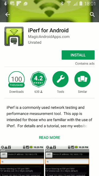
2.5.2 iPerf Install on UE side
You also need to install iPerf on your device under test. iPerf is available in Google Play for Android as shown below.
2.6 UDP/TCP configuration
UDP does not require any particular configuration neither on the operating system side nor on iPerf side.
For TCP, in order to achieve maximum throughput, the TCP advertised receiver window size must be equal to or greater than the BDP (Bandwidth Delay Product), which can be expressed as follows:
BDP = TCP Bandwidth * RTT
Where
TCP bandwidth is the portion of the radio bearer used to send TCP data. This is the data rate that you would like to achieve based on your UE category and cell configuration. RTT is the Round Trip Time between TCP end-points as seen by the TCP sender. In order to have an idea of the RTT of your link, you can ping your UE from the core network PC.
Please note that some operating systems have limitations on max TCP window size. You can of course tweak your phone if you are root. If you have an Android device, you can check the following parameters with root privilege:
- -
/proc/sys/net/ipv4/tcp_rmem: memory reserved for TCP receive buffers - -
/proc/sys/net/ipv4/tcp_wmem: memory reserved for TCP send buffers - -
/proc/sys/net/core/rmem_max: maximum receive window - -
/proc/sys/net/core/wmem_max: maximum send window
Parallel TCP connections could certainly help improve the TCP throughput if you can not change the above parameters in your device. With iPerf, you can use the -P <n> option to start n parallel TCP connections.
2.7 Step by Step Throughput Testing
This section provides step by step instructions to test throughput using iPerf.
2.7.1 DL throughput test
To do a simple downlink test in MIMO CAT 4 at 150 Mbps in UDP, you can proceed as follows:
- Edit the configuration file enb.cfg and change N_RB_DL to 100 and N_ANTENNA_DL to 2
- Start your eNodeB using the configuration file enb.cfg
- run iPerf in server mode at the UE side
iperf -s -u -i 1
- Run iPerf in client mode on your core network PC
iperf -c <UE IP address> -u -b 150M -i 1 -t 100
You can obtain the UE IP address, by typing
uecommand on MME monitor.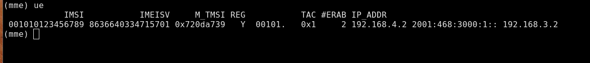
- Run the
tcommand in eNodeB screen to activate UE statistics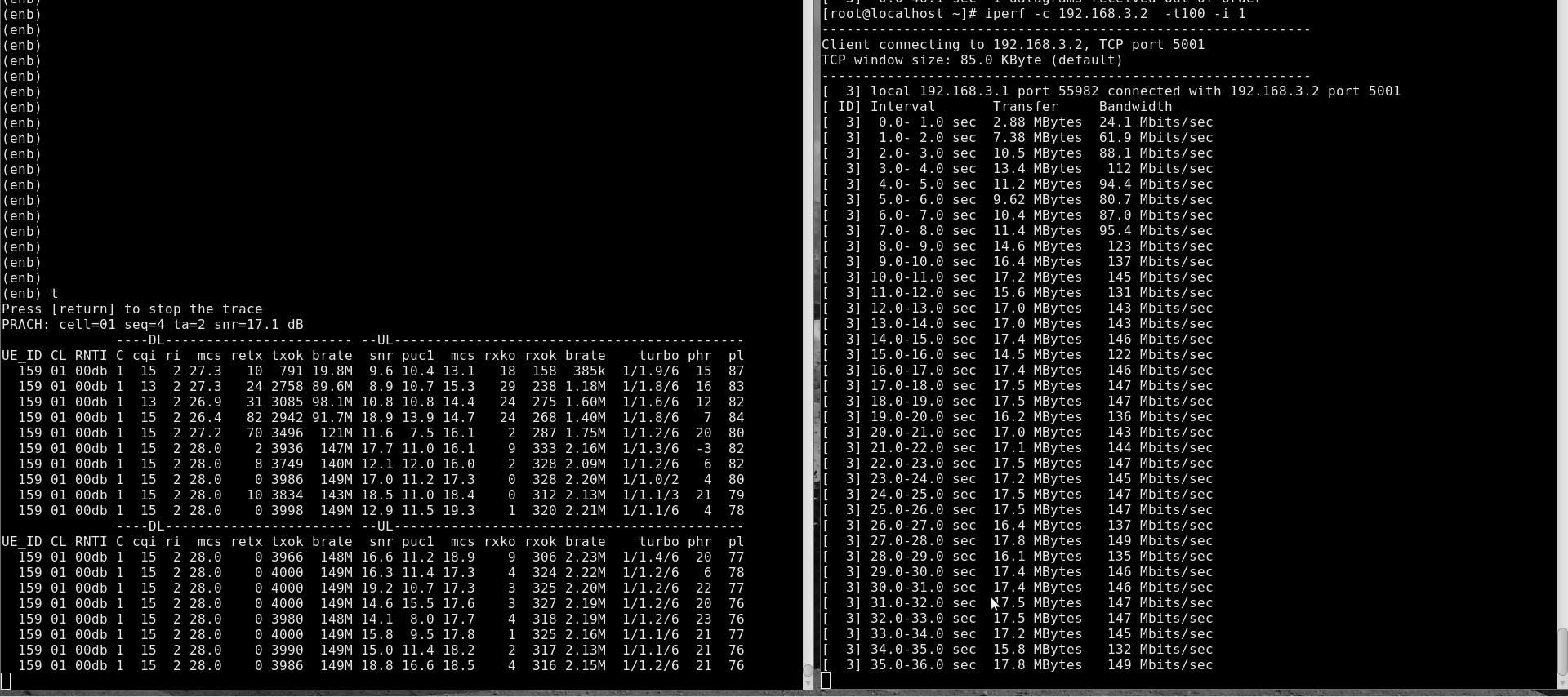
You can check
bratefield in DL eNodeB stats for downlink throughput. You can as well check the iPerf application level throughput at the server window.
For a TCP connection, the steps are the same as above except for iPerf command. At UE side, you need to start iPerf in server mode as below:
iperf -s -i 1
The command to be used at core network PC side is:
iperf -c <UE IP address> -i 1 -t 100
2.7.2 UL throughput test
To do a simple uplink test in MIMO CAT 4 at 50 Mbps in UDP, you can proceed as follows.
- Edit the configuration file enb.cfg and change N_RB_DL to 100
- Start your eNodeB using the configuration file mimo-2x2-20mhz.cfg
- Run the following command on your core network PC
iperf -s -u -i 1
- run iPerf in client mode at the UE side
iperf -c <PDN Gateway IP address> -u -b 50M -i 1 -t 100
Where the
PDN Gateway IP addresscould be found by looking atgatewayparameter of thepdnobject inLTEMMEconfig file. In default configuration files, thegatewayparameter is not set for PDNs. In this case, the first IP of the subnet in IPv4 will be used as gateway IP address.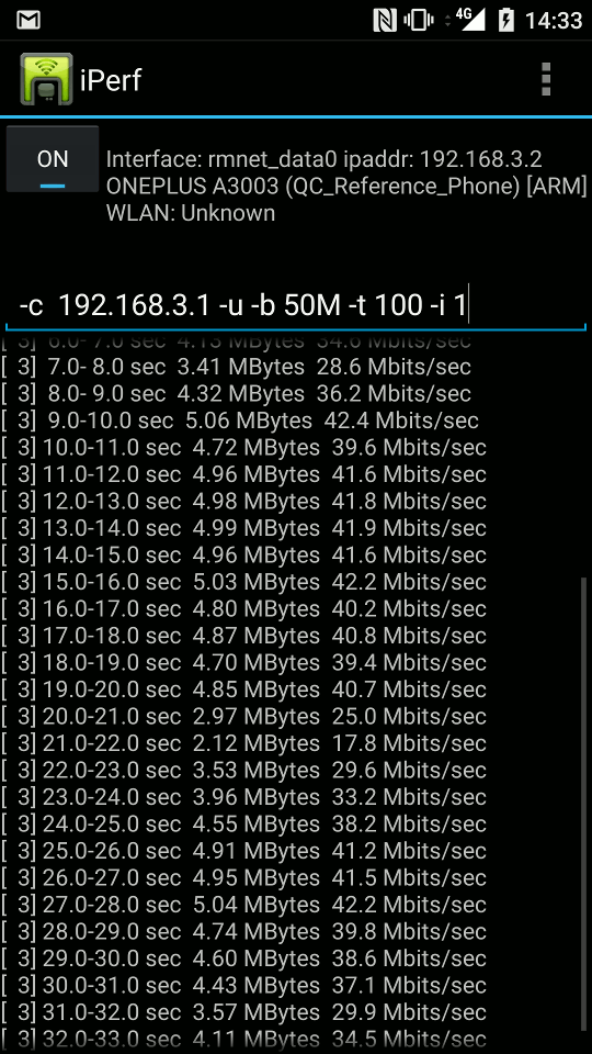
- Run the
tcommand in eNodeB screen to activate UE statistics.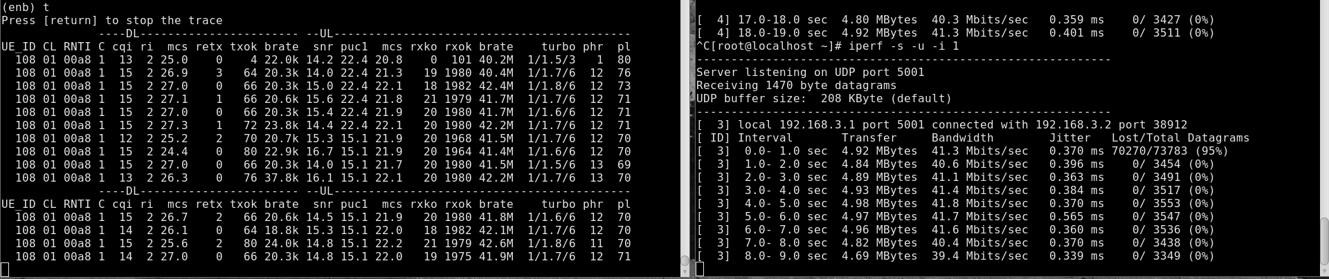
You can check brate field in UL eNodeB stats for uplink throughput. You can as well check the iPerf application level throughput at the server window.
For a TCP connection, the steps are the same as above except for iPerf command. At the core network PC side, you can type the following command:
iperf -s -i 1
At the UE side, the command to run is as below:
iperf -c <PDN GATEWAY IP address> -i 1 -t 100
2.7.3 Simultaneous UL/DL throughput test
For simultaneous UL/DL test, you need to either run two instances of iPerf, one in UL and one in DL as described above or to use the -d option.
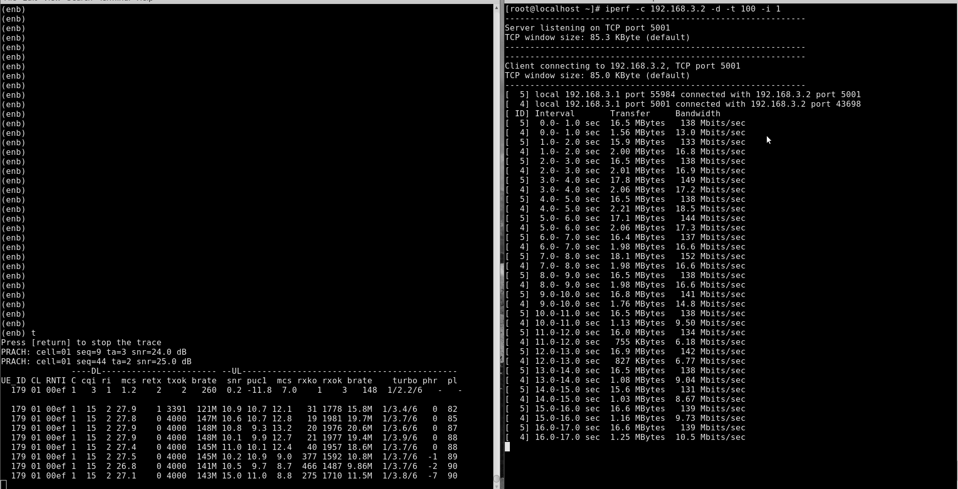
The below example is for bi-directional TCP test. On your core network PC, you can run
iperf -c <UE IP address> -d -i 1 -t 100
On your device, you can run
iperf -s -i 1
Following is an example of UE statistics when running simultaneous UL/DL throughput test:
3 Logging
The Amarisoft eNodeB generates a log file at /tmp/enb0.log that could be used for for further analysis and debugging. Best is to activate physical layer debug traces by adding phy.level=debug to log_options field in your eNodeB config file.
4 Troubleshooting
Below are some of the most common issues encountered during testing with recommended actions to address each issue.
| Issue | Cause/Correction |
|---|---|
| Can not achieve maximum data rate in DL |
|
| Can not achieve maximum data rate in UL |
|
5 Additional Information
This document is copyright (C) 2012-2026 Amarisoft. Its redistribution without authorization is prohibited.
This document is available without any express or implied warranty and is subject to change without notice. In no event will Amarisoft be held liable for any damages arising from the use of this document.
For any technical issue, please raise a ticket from our support site at https://support.amarisoft.com/.
To learn more about our technology and solutions, e-mail us at customer@amarisoft.com or visit https://www.amarisoft.com.