Intra and Inter eNB handover version 2026-03-16*This document is based on the latest test release.
Features may not be present in your current installed software. You may check their availability in your release documentation.
If you require an up to date release, ask for it in a ticket.
Features may not be present in your current installed software. You may check their availability in your release documentation.
If you require an up to date release, ask for it in a ticket.
Table of Contents
- 1 Introduction
- 2 Handover Intra eNB
- 3 Handover inter eNB
- 4 Handover using UE simulator
- 5 Handover call flow
- 6 5G SA Handover
- 7 Troubleshooting
1 Introduction
This application notes aims to provide the procedure for running intra and Inter eNB/gNB handover scenarios on Amarisoft products using commercial UE.
In the case where handover tests are run with Amarisoft UE simulator (instead of commercial UE), please See handover using UE simulator for UE prerequisites and parameters.
2 Handover Intra eNB
2.1 LTE Network architecture
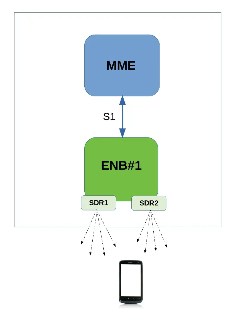
Setup is composed of :
- One MME and one eNB running on same PC and connected through S1 interface
- One or Two SDR cards
2.2 Constraints
In order to test Inter Frequency/Band handover between two cells running on same eNB, one or two SDR cards are required depending on the spectrum used by both cells.
PCIe SDR cards have a bandwidth of 56Mhz (USRP N2x0 is 40Mhz). By consequence, if both cells can fit in this bandwidth, handover can be carried out with one SDR only. Otherwise, two SDR cards are required.
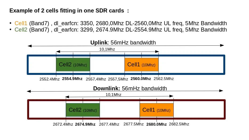
In the example above, there is no overlap between the two cells neither in Uplink nor in downlink.
If a higher bandwidth had been used (20Mhz as instance), both cells would have overlapped, resulting in interference.
Others constraints:
- The difference of the center frequencies of each cell must be a multiple of 300 kHz (hence the difference of their EARFCN must be a multiple of 3).
- The difference between the center frequency of each cell and the average of center frequencies must be a multiple of 15 kHz.
- The number of cells that could be configured in a frequency band depends on the total bandwidth of the lte band and the configured bandwidth of each cell + the offsets.
- The cells must have the same
prach-ConfigIndex(SIB2), i.e. their PRACH must have the same duration and transmitted in the same subframes. - Multiple cells can be set at the same frequency provided their physical cell identity (
n_id_cellproperty) and PRACHrootSequenceIndex(SIB2) are different to minimize the inter-cell interference. In the current version, there is no resource reservation among the cells, so a performance degradation happens if they transmit at the same time in the same resource blocks. So it is currently better to use cells at different frequencies.
Let’s take the following example to configure 3 cells in band 7:
cell 1 DL frequency: 2627 MHz
cell 2 DL frequency: 2642 MHz
cell 3 DL frequency: 2657 MHz
average_dl_freq = (2627+2642+2657)/3 = 2642 MHz
cell1_freq_offset = 2627-2642 = -15 MHz
cell2_freq_offset = 2642-2642 = 0 MHz
cell3_freq_offset = 2657-2642 = 15 MHz
We can observe that the difference between the center frequency of each cell and the average of center frequencies is indeed a multiple of 15 kHz and the difference between the DL EARFCNs are a multiple of 3.
2.3 MME configuration
For running intra eNB Handover, no specific configuration is required on MME side. Default configuration files can be used without customization
2.4 eNB configuration with both cells running on same SDR card
As described in previous section, it’s possible to configure two or more cells on the same SDR card as long as it fulfills the spectrum constraints. See constraints for more details.
2.4.1 Neighbor cell info
In enb.cfg file, for each cell, set neighbour cell info using ncell_list parameters:
/* high 24 bits of SIB1.cellIdentifier */
  enb_id: 0x1A2E0,

cell_list: [
  {
    dl_earfcn: 3350,  /* DL center frequency: 2680 MHz (Band 7) */

    n_id_cell: 1,
    cell_id: 0x01,
    tac: 0x0001,
    root_sequence_index: 204, /* PRACH root sequence index */

    /* Neighbour cell list (used for handover) */
    ncell_list: [
      { n_id_cell: 2, dl_earfcn: 3299, cell_id: 0x1a2e002, tac: 1 },
    ],
  },
  {
    dl_earfcn: 3299, /* DL center frequency: 2674.9 MHz (Band 7) */

    n_id_cell: 2,
    cell_id: 0x02,
    tac: 0x0001,
    root_sequence_index: 86, /* PRACH root sequence index */

    /* Neighbour cell list (used for handover) */
    ncell_list: [
      { n_id_cell: 1, dl_earfcn: 3350, cell_id: 0x1a2e001, tac: 1 },
    ],
  },
  ], /* cell_list */
where:
-
n_id_cellis n_id_cell of neighbour cell -
dl_earfcnis the downlink earfcn of neighbour cell -
cell_idis the EUTRAN cell identifier (concatenation of theenb_idandcell_idof neighbour cell)
Please refer to lteenb.pdf for more details about cell list parameters
2.4.2 Measurement configuration
In order to trigger measurement reports (a1,a2 and a3) at UE side when cells level will fluctuate, set meas_config_desc parameters in enb.cfg file (under cell_default object) :
Example:
    /* measurement configuration */
    meas_config_desc: {
        a1_report_type: "rsrp",
        a1_rsrp: -70,
        a1_hysteresis: 0,
        a1_time_to_trigger: 640,
        a2_report_type: "rsrp",
        a2_rsrp: -80,
        a2_hysteresis: 0,
        a2_time_to_trigger: 640,
        eutra_handover: {
          a3_report_type: "rsrp",
          a3_offset: 6,
          hysteresis: 0,
          time_to_trigger: 480
        }
    },

    /* measurement gap configuration */
    meas_gap_config: "gp0",

    /* if true, initiate a handover when a suitable measurement report
       is received */
    ho_from_meas: true,
Please refer to lteenb.pdf for more details about meas_config_desc parameters
2.5 eNB configuration with cells running on two SDR card
For Inter frequency/band handover two SDR cards may be required if spectrum used by both cells is larger than SDR bandwidth (56Mhz for PCIe SDR card) .
In that case, cell configuration is slightly different and rf_port used by each cell must be defined.
Others parameters (Neighbor cell info and Measurement configuration) remain identical.
Example:
 cell_list: [
  {
    rf_port: 0, /* means that cell 0x01 will use dev0=/dev/sdr0 */
    dl_earfcn: 3350,  /* DL center frequency: 2680 MHz (Band 7) */
    n_id_cell: 1,
    cell_id: 0x01,
    tac: 0x0001,
    root_sequence_index: 204, /* PRACH root sequence index */
    /* Neighbour cell list (used for handover) */
    ncell_list: [
      { n_id_cell: 2, dl_earfcn: 3299, cell_id: 0x1a2e002, tac: 1 },
    ],
  },
  {
    rf_port: 1,  /* means that cell 0x02 will use dev1=/dev/sdr1 */
    dl_earfcn: 3299, /* DL center frequency: 2674.9 MHz (Band 7) */
    n_id_cell: 2,
    cell_id: 0x02,
    tac: 0x0001,
    root_sequence_index: 86, /* PRACH root sequence index */

    /* Neighbour cell list (used for handover) */
    ncell_list: [
      { n_id_cell: 1, dl_earfcn: 3350, cell_id: 0x1a2e001, tac: 1 },
    ],
In config/rf_driver, both SDR cards must be defined as well. See trx_sdr.pdf for more details.
rf_driver: {
    name: "sdr",

    /* list of devices. 'dev0' is always the master. */
    args: "dev0=/dev/sdr0,dev1=/dev/sdr1",
|
Note: When two SDR cards are used on same eNB, SDR1 must be connected to SDR0 through USB cable provided by Amarisoft in order to synchronize the Radio frames. See installguide.pdf for more details. |
2.6 Handover triggered by UE measurement report
In order to carry out handover based on UE measurement report, once enb is configured, the only thing to do is to decrease step by step cell gain at eNB side (command cell_gain cell_id gain on eNB screen) . Example : cell_gain 1 -20
|
Note: To perform handover and not a reselection, it’s recommended to run uplink or downlink transfer using iperf as instance in order to keep UE in RRC connected state |
2.7 Blind handover triggered by eNB
In order to carry out blind handover, eNB command can be used. To do this:
- Start downlink or Uplink transfer (with iperf as instance) in order to keep UE in RRC connected state
- On eNB screen, enter
uecommand to identify UE id at eNB level (eNB_UE_ID) - Enter
handovercommand with the following parameters : eNB_UE_ID pci dl_earfcn type
Where :
- eNB_UE_ID is UE ID at eNB level
- pci is physical Cell ID of target cell (neighbor cell).
- dl_earfcn is downlink earfcn of target cell (neighbor cell).
- type is handover type. Use
intrahere.
Example of handover command : handover 14 2 3299 intra
3 Handover inter eNB
3.1 Prerequisites
In order to test handover between two different eNB, some prerequisites must be fulfilled:
- Each eNB must be running on a different PC (host). It’s not possible to run 2 eNB components on same Hardware.
- By consequence two eNB licenses are required to run inter eNB handover scenario. Only one MME license is needed.
- Radio frames must be synchronized between eNB1 and eNB2.
The most convenient way is to use GPS antenna on both eNB. Any active GPS antenna accepting a 3.3V DC supply can be used, - Each eNB is configured with one cell (using one SDR card). UE can attach on each cell independently
Note: MME component can be run on same PC as eNB. This will be the setup described in this document
3.2 LTE Network architecture
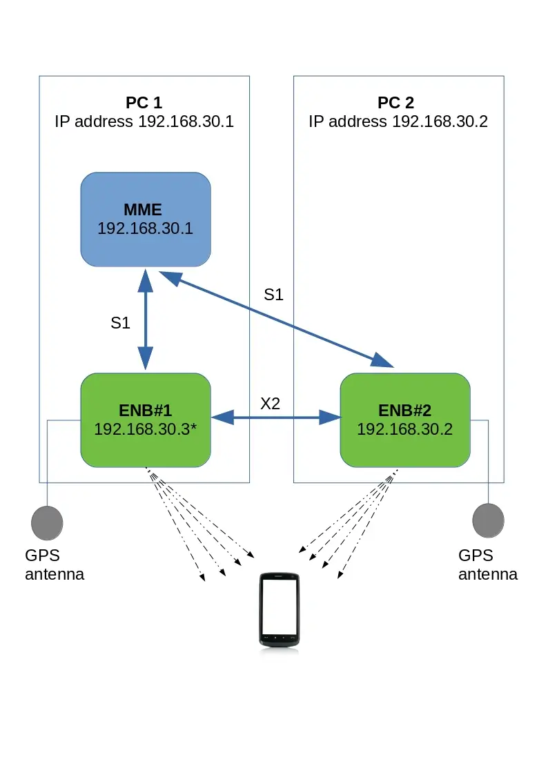
Setup is composed of :
- One MME and one eNB (named eNB1) running on the same PC (IP address 192.168.30.1)
- A second eNB (eNB2) running on a different PC (IP address 192.168.30.2)
MME and both eNB connected through S1 interface
eNB1 and eNB2 connected through X2 interface
3.3 MME configuration
In order to connect both eNB to same MME, default (loopback) GTP address must be changed and replaced with IP address of PC where MME component is running.
in mme.cfg file, change :
gtp_addr: "127.0.1.100",
with
gtp_addr: "192.168.30.1",
|
Note: If another MME component is running on PC where eNB2 is running, this one must be turned off. |
3.4 eNB1 configuration
This section aims to describe the modifications required on eNB to carry out inter eNB handover.
The initial setting of eNB (cell, earfcn , gain, SDR configuration, etc.. ) are not covered in this document.
Please refer to lteots.pdf document for more details on basic configurations.
3.4.1 MME address
In enb.cfg file, replace default (loopback) MME address with IP address of PC1 (192.168.30.1).
mme_list: [
    {
      /* address of MME for S1AP connection. Must be modified if the MME
         runs on a different host. */
      mme_addr: "192.168.30.1",
    },
  ],
3.4.2 GTP address
As for MME, default GTP address must be changed and replaced with IP address of the PC1 (instead of using loopback IP address).
However, as IP address of PC1 is already used by MME, it’s not possible to reuse it.
The solution is to create an IP alias (192.168.30.3 as instance) and use this alias as gtp_addr for eNB1.
To create the alias:
- Run
ifconfigcommand - Check ethernet interface name (example "eth2:" )
- Enter command
ifconfig eth2:1 192.168.30.3/24 - Check alias has been created with
ifconfigcommand
|
Note: This hint is not needed if MME is running on its own PC and don’t have, as consequence, the same IP address as eNB1. |
Once the IP alias has been created , update enb.cfg file and replace default gtp_addr with this value
/* GTP bind address (=address of the ethernet interface connected to
     the MME). Must be modified if the MME runs on a different host. */
  gtp_addr: "192.168.30.3",
3.4.3 X2 address
In order to connect both eNB through X2 interface, X2 peer IP address (eNB2) must be set .
In enb.cfg file , add the following parameter :
x2_peers:["192.168.30.2"],
3.4.4 eNB ID
Each eNB must have a unique ID. The default value is:
enb_id: 0x1A2D0
3.4.5 Neighbor cell info
In enb.cfg file, set neighbour cell (eNB2 cell) info using ncell_list parameters:
cell_list: [
  {
    dl_earfcn: 3350,  /* DL center frequency: 2680 MHz (Band 7) */

    n_id_cell: 1,
    cell_id: 0x01,
    tac: 0x0001,
    root_sequence_index: 204, /* PRACH root sequence index */

    /* Neighbour cell list (used for handover) */
    ncell_list: [
      { n_id_cell: 2, dl_earfcn: 6300, cell_id: 0x1A2D101, tac: 1 },
    ],
  },
where:
-
n_id_cellis n_id_cell of eNB2 cell -
dl_earfcnis the downlink earfcn of eNB2 cell -
cell_idis the EUTRAN cell identifier (concatenation of theenb_idandcell_idof eNB2 cell)
3.4.6 Measurement configuration
In order to trigger measurement reports (a1,a2 and a3) at UE side when cells level will fluctuate, set meas_config_desc parameters in enb.cfg file (under cell_default object) :
Example:
    /* measurement configuration */
    meas_config_desc: {
        a1_report_type: "rsrp",
        a1_rsrp: -70,
        a1_hysteresis: 0,
        a1_time_to_trigger: 640,
        a2_report_type: "rsrp",
        a2_rsrp: -80,
        a2_hysteresis: 0,
        a2_time_to_trigger: 640,
        eutra_handover: {
          a3_report_type: "rsrp",
          a3_offset: 6,
          hysteresis: 0,
          time_to_trigger: 480
        }
    },

    /* measurement gap configuration */
    meas_gap_config: "gp0",

    /* if true, initiate a handover when a suitable measurement report
       is received */
    ho_from_meas: true,
Please refer to lteenb.pdf for more details about meas_config_desc parameters
3.4.7 SDR clock setting
As described in hardware prerequisite section, both eNB must be synchronized using a GPS clock antenna.
If PCIe SDR cards are used on your setup, the synchronization source must be changed.
In /root/enb/config/rf_driver folder, open config file used by enb.cfg file and uncomment sync parameter.
 /* synchronization source: internal, gps, external (default = internal) */
     sync: "gps",
Whith this modification, PCIe SDR card will get its clock from the GPS antenna.
3.5 eNB2 configuration
3.5.1 MME address
As for eNB1 , in enb.cfg file, replace default (loopback) MME address with IP address of PC where MME component is running (192.168.30.1).
mme_list: [
    {
      /* address of MME for S1AP connection. Must be modified if the MME
         runs on a different host. */
      mme_addr: "192.168.30.1",
    },
  ],
3.5.2 eNB ID
As both eNB are connected to same MME component, their ID must be different.
In enb.cfg file change enb_id to be different of eNB1
/* high 24 bits of SIB1.cellIdentifier */
  enb_id: 0x1A2D1,
3.5.3 GTP address
As for eNB1 , GTP address must be changed.
However, as there is no MME component on this PC (eNB2 only), the IP constraint encountered with eNB1 is not present and GTP address can be the one of PC2
/* GTP bind address (=address of the ethernet interface connected to
     the MME). Must be modified if the MME runs on a different host. */
  gtp_addr: "192.168.30.2",
3.5.4 X2 address
As for eNB1, X2 peer IP address (eNB1) must be set.
In enb.cfg file, add the following parameter:
x2_peers:["192.168.30.1"],
3.5.5 Neighbor cell info
As for eNB1, in enb.cfg file, set neighbour cell (eNB1 cell) info using ncell_list parameters:
cell_list: [
  {
    dl_earfcn: 6300,  /* DL center frequency: 2680 MHz (Band 7) */

    n_id_cell: 2,
    cell_id: 0x01,
    tac: 0x0001,
    root_sequence_index: 204, /* PRACH root sequence index */

    /* Neighbour cell list (used for handover) */
    ncell_list: [
      { n_id_cell: 1, dl_earfcn: 3350, cell_id: 0x1A2D001, tac: 1 },
    ],
  },
where:
-
n_id_cellis n_id_cell of eNB1 cell -
dl_earfcnis the downlink earfcn of eNB1 cell -
cell_idis the EUTRAN cell identifier (concatenation of theenb_idandcell_idof eNB1 cell),
3.5.6 Measurement configuration
As for eNB1 , in enb.cfg file, under cell_default object, set meas_config_desc parameters:
Example :
    /* measurement configuration */
    meas_config_desc: {
        a1_report_type: "rsrp",
        a1_rsrp: -70,
        a1_hysteresis: 0,
        a1_time_to_trigger: 640,
        a2_report_type: "rsrp",
        a2_rsrp: -80,
        a2_hysteresis: 0,
        a2_time_to_trigger: 640,
        eutra_handover: {
          a3_report_type: "rsrp",
          a3_offset: 6,
          hysteresis: 0,
          time_to_trigger: 480
        }
    },

    /* measurement gap configuration */
    meas_gap_config: "gp0",

    /* if true, initiate a handover when a suitable measurement report
       is received */
    ho_from_meas: true,
Please refer to lteenb.pdf for more details about meas_config_desc parameters
3.6 GPS antenna connection
3.6.1 Connection
- Place your GPS antenna in a place where GPS signal is likely to be found (outdoor).
- Connect each GPS antenna to SMA connector
GPSof PCIe SDR card on eNB1 and eNB2.
3.6.2 GPS test
Once connection is done, you can check if GPS clock is locked. To do this :
- Stop LTE service on your PC (service lte stop)
- Go under
/root/trx_sdrfolder - Enter the command
./sdr_util -c 0 gps_state - If GPS clock is locked, date and time will be displayed :
    GPS locked
    TAI: 2018-11-20 16:18:29
    UTC: 2018-11-20 16:17:52
|
Note: The GPS takes a few minutes to lock if the GPS antenna is connected. |
3.7 S1 and X2 connection check
Once eNB1,eNB2 and MME have be configured, you can start each component and check the connections.
- On MME screen, enter
enbcommand. Both eNB should be listed - On both eNB screen, enter
s1command. S1 connection state should be "setup_done" - On both eNB screen, enter
x2command. X2 Peer connection state should be "setup_done" - If X2 peer connection state is "disconnected", just enter
x2connectcommand and check again withx2command afterwards.
Your setup is now completed ! You can connect your UE and run handover test .
3.8 S1/X2 Handover triggered by UE measurement report
In order to carry out Handover based on UE measurement report, the only thing to is to decrease step by step cell gain at eNB side (command cell_gain cell_id gain on eNB screen) . Example : cell_gain 1 -20
To trigger a S1 handover rather than X2, just remove the x2_peers connection in eNB configuration files
|
Note: To perform Handover and not a reselection, it’s recommended to run uplink or downlink transfer with iperf as instance in order to keep UE in RRC connected state |
3.9 Blind S1/X2 Handover triggered by eNB
In order to carry out blind X2 or S1 handover, eNB command can be used. To do this:
- Start downlink or Uplink transfer (with iperf as instance) in order to keep UE in RRC connected state
- On eNB screen, enter
uecommand to identify UE id at eNB level (eNB_UE_ID) - Enter
handovercommand with the following parameters : eNB_UE_ID pci dl_earfcn type
Where :
- eNB_UE_ID is UE ID at eNB level
- pci is physical Cell ID of target cell (eNB2).
- dl_earfcn is downlink earfcn of target cell (eNB2).
- type is handover type. Can be intra, s1 or x2.
Example of X2 handover command : handover 14 2 3350 x2
4 Handover using UE simulator
4.1 Hardware prerequisite
When Amarisoft UE simulator is used for testing handover, two SDR cards are required. SDR1 card will be connected to cell 1, SDR2 card will be connected to cell 2.
4.2 UE configuration file
In ue.cfg file, both cells must be declared
Example :
cells: [
    {
      dl_earfcn: 6300,
      n_antenna_dl: 2,
      n_antenna_ul: 1,
    },
    {
      dl_earfcn: 3350,
      n_antenna_dl: 2,
      n_antenna_ul: 1,
    },
  ],
On top of that, SDR mapping must be defined :
Example :
rf_driver: {
    name: "sdr",
    args: "dev0=/dev/sdr0,dev1=/dev/sdr1",
    },
The mapping between Cells and SDR cards is made automatically and follows the same order as the declaration in the configuration file.
The example here above results in:
- SDR card#0 listening on earfcn 6300
- SDR card#1 listening on earfcn 3350
The RF connection must be done accordingly.
For 5G SA handover similar concepts apply, for that please refer to the provided example configuration file ue-nr-2cc-sa.cfg.
|
Note: When two cells are declared on UE side, both cells must be active otherwise UE will remain in SIB detection state indefinitely |
5 Handover call flow
5.1 X2 Handover triggered by UE measurement
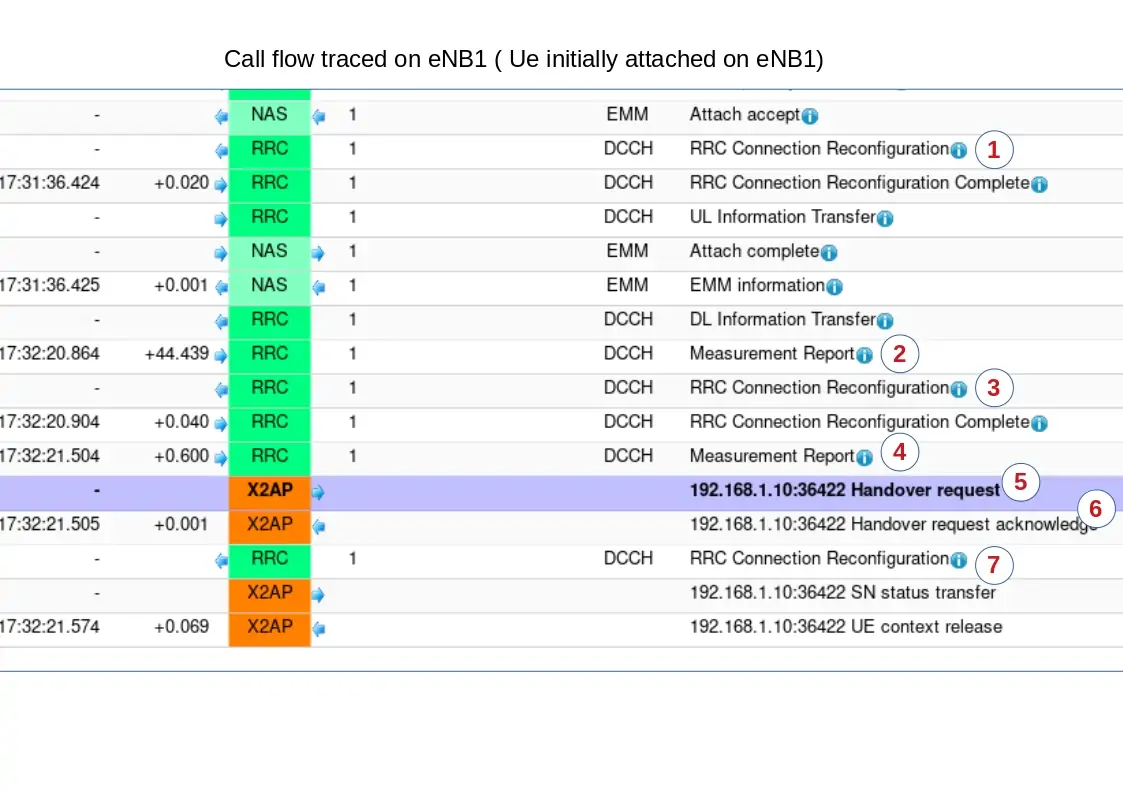
- RRC Connection Reconfiguration:
Sent by eNB to UE to configure measurement report events
Three event reportsa1,a2,a3are configured inRRC Connection Reconfiguration
Two event reportsa2,a3are activatedExample of a1 report configuration within RRC Connection Reconfiguration message:
reportConfigToAddModList {
          {
            reportConfigId 1,
            reportConfig reportConfigEUTRA: {
              triggerType event: {
                eventId eventA1: {
                  a1-Threshold threshold-RSRP: 90
                },
                hysteresis 0,
                timeToTrigger ms640
              },
              triggerQuantity rsrp,
              reportQuantity both,
              maxReportCells 1,
              reportInterval ms120,
              reportAmount r1
            }
- Measurement Report A2:
Sent by UE to eNB when the serving cell becomes worse than a threshold
 message c1: measurementReport: {
    criticalExtensions c1: measurementReport-r8: {
      measResults {
        measId 2,
        measResultPCell {
          rsrpResult 79,
          rsrqResult 34
        }
      }
- RRC Connection Reconfiguration:
Upon reception ofa2meas report, network reconfigures UE event report (deactivatea2, activatea1and activate Measurement Gap) throughRRC Connection Reconfigurationmessage
Note: Measurement Gap have an impact on throughput as no transmission and reception happens during gap periods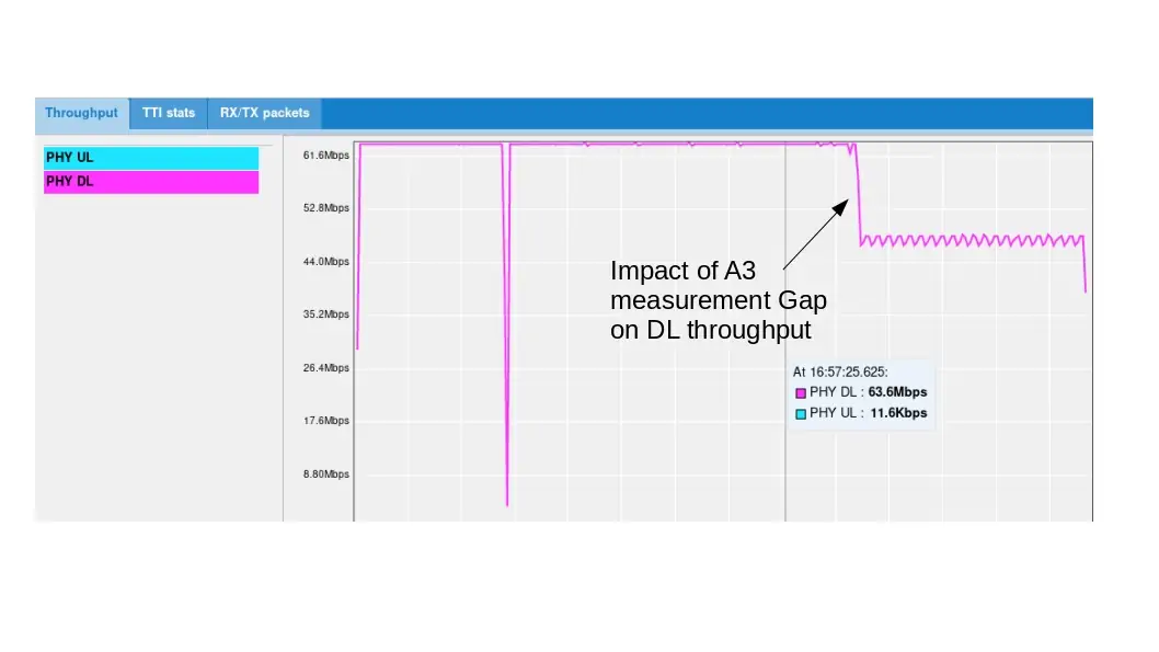
- Measurement Report A3:
Sent by UE to eNB when a neighbouring cell becomes better than the serving cell by an offset
Upon reception ofa3meas report, network trigger the Handover through X2 interfacemessage c1: measurementReport: { criticalExtensions c1: measurementReport-r8: { measResults { measId 3, measResultPCell { rsrpResult 79, rsrqResult 34 }, measResultNeighCells measResultListEUTRA: { { physCellId 2, measResult { rsrpResult 90, rsrqResult 34 }
- Handover request:
Sent by eNB1 to eNB2 to set up the inter eNB handover through X2AP interface (X2AP trace level must be set to "debug" to see this message)
- Handover request acknowledge:
Sent by eNB2 to eNB1 to acknowledge eNB handover
- RRC Connection Reconfiguration:
Once eNB2 acknowledges the X2 handover request, eNB1 triggers a handover at UE side by sending theRRCconnectionReconfiguration.
This message provides mobility information as described below as well as target cell information for UE to establisgh a RRC connection request on target cell.mobilityControlInfo { targetPhysCellId 2, carrierFreq { dl-CarrierFreq 3350 },
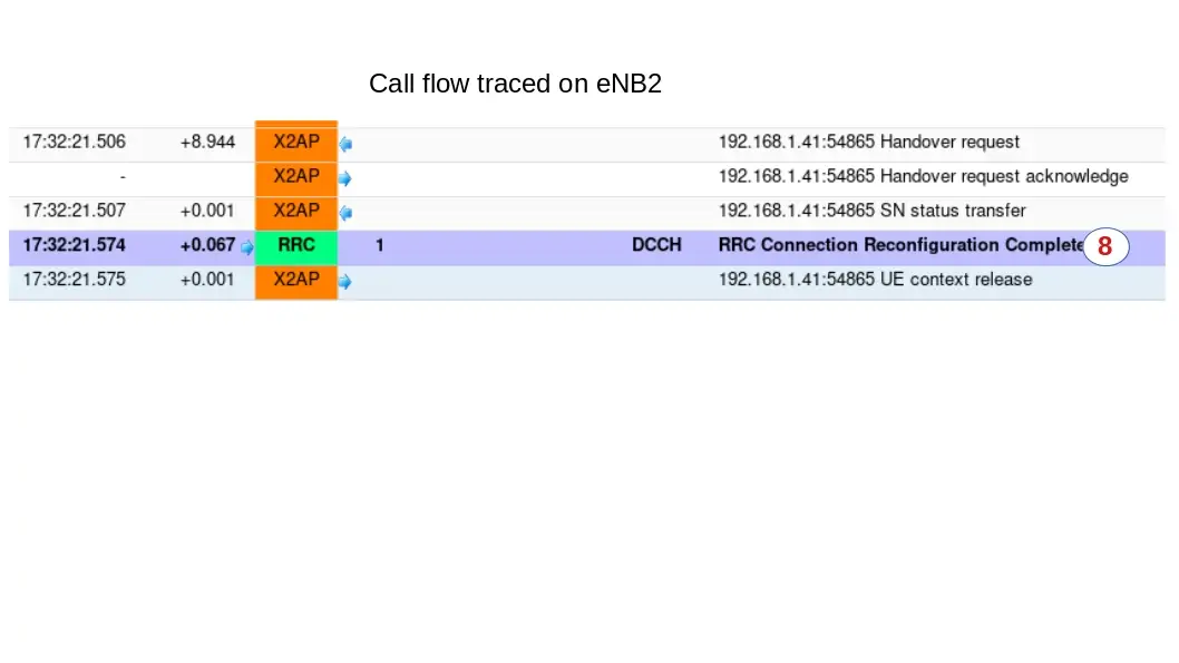
- RRC Connection Reconfiguration Complete:
Once UE has moved from eNB1 to eNB2 , it sends theRCC Connection Reconfiguration Completeon the target cell (eNB2)
To see this message, a log must be captured on eNB2 this time
Traffic should be now resumed on target cell.
5.2 S1 Handover triggered by UE measurement
S1 inter eNB handover has the same call flow as X2 handover when it comes to the messages exchanged between UE and eNB (See X2 handover call flow for more details).
The main difference is on the Handover procedure at eNB side. Handover request is sent to MME through S1 interface and not to peer eNB through X2 interface.
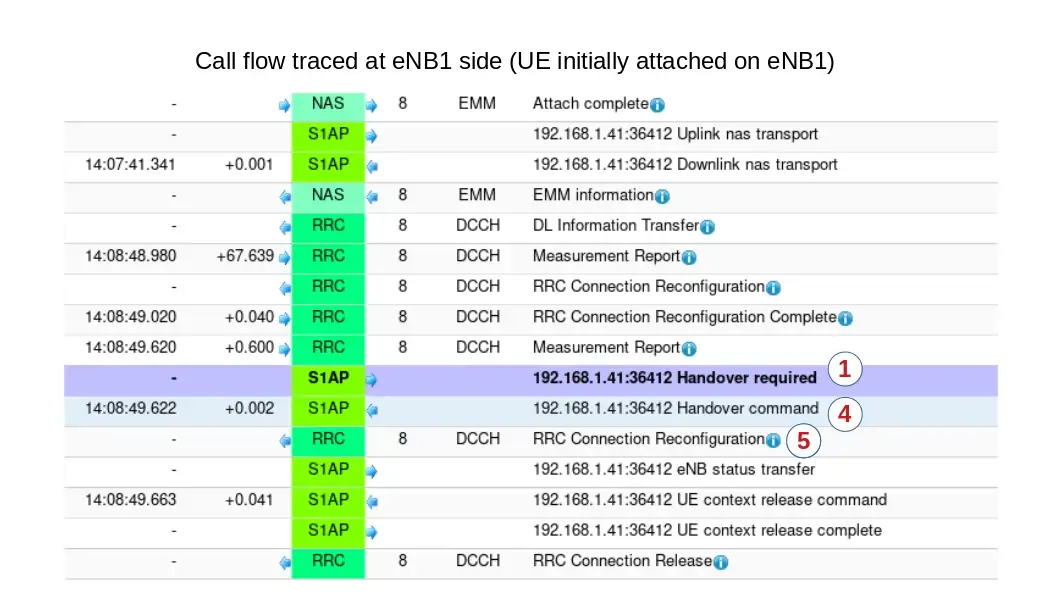
- Handover required:
Upon reception of Measurement Report A3, eNB1 triggers a Handover by sending aHandover requiredto MME. The source eNodeB indicates which bearers are subject to data forwarding.
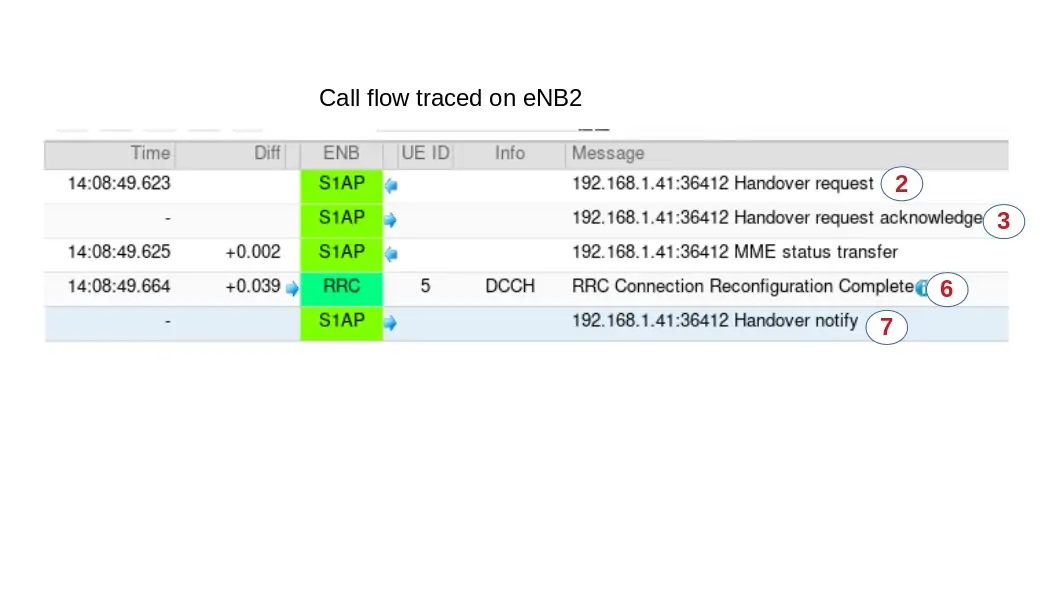
- Handover Request:
MME sendsHandover Requestmessage to the target eNodeB. This message creates the UE context in the target eNodeB, including information about the bearers, and the security context
- Handover Request Acknowledge:
Target eNodeB responds back to the MME with aHandover Request Acknowledgemessage. This message carries the Handover Command message (RRC Connection Reconfiguration Request) in a transparent container
- Handover Command:
MME sends a Handover Command message to the source eNodeB.
- RRC Connection Reconfiguration:
Upon reception of the Handover command, source eNB sends theRRC Connection Reconfigurationmessage to the UE. The message contains a new C-RNTI and new DRB IDs. Upon reception of this message the UE will remove any EPS bearers for which it did not receive the corresponding EPS radio bearers in the target cell.
- RRC Connection Reconfiguration Complete:
UE uses the preamble assigned in the handover command to send a RACH to the target eNodeB. The target eNodeB accepts the request and responds back with a timing adjustment and an uplink resource. UE uses the assigned resources to transmit theRRC Connection Reconfiguration Complete(Handover Confirm message)
- Handover Notify:
Target eNodeB sends a Handover Notify message to MME. Handover is successful
6 5G SA Handover
6.1 Intra gNB Handover
The gNodeB can run several NR cells. The cells can be configured individually and share the same NG interfaces with the Core Network.
Cells can be configured on one (intra-band) or several (intra/inter band) SDR cards. Refer to lteenb.pdf, section 7.6.1, for limitations related to intra-band cells configured on the same SDR card.
An example of multi cell configuration for SA handover is given in config/gnb-sa-ho.cfg.
For each cell, a list of neighbor cells can be provided as in the example below:
ncell_list:
[
  {
    rat: "nr",
    cell_id: 0x02,
  }
],
where cell_id is the cell_id of the neighbor cell.
The handover can be manually initiated with the handover monitor command, the handover remote API, or automatically initiated based on UE measurements.
In case of handover based on UE measurement reports, a measurement object can be configured as in the example below:
/* measurement configuration */
    meas_config_desc: {
      a1_report_type: "rsrp",
      a1_rsrp: -60,
      a1_hysteresis: 10,
      a1_time_to_trigger: 100,
      a2_report_type: "rsrp",
      a2_rsrp: -70,
      a2_hysteresis: 0,
      a2_time_to_trigger: 100,
      nr_handover: {
        a3_report_type: "rsrp",
        a3_offset: 6,
        hysteresis: 0,
        time_to_trigger: 100
      }
    },
    meas_gap_config: {
      pattern_id: 0
    },
For handover procedure triggered by UE measurement report refer to Handover triggered by UE measurement report.
To perform blind intra gNB handover triggered by gNB, the handover command or remote API can be used, refer to lteenb.pdf for more details.
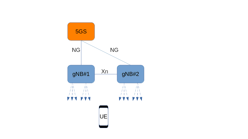
6.2 Inter gNB Handover
The same prerequisites as per inter-eNB Prerequisites apply.
In case of inter gNB Handover (XnAP or NGAP), each gNB runs on a different host and they are both connected to the same AMF. AMF can run on one of the gNB machine or on a third one. The gtp_address defined in each gNB configuration has to be set to the address of the ethernet interface connected to the AMF.
/* GTP bind address (=address of the ethernet interface connected to
     the AMF). Must be modified if the AMF runs on a different host. */
  gtp_addr: "192.168.30.1",
As both gNBs are connected to same AMF component, their ID must be different.
Use a unique gnb_id on each configuration file.
gnb_id: 0x12345,
Each gNB configuration must define the serving cell and a list of fully described neighbor cells, as in the example below:
nr_cell_list: [
{
  rf_port: 0,
  cell_id: 0x01,
  n_id_cell: 500,

  band: 78,
  dl_nr_arfcn: 621300,

  ncell_list: [
  {
    ssb_nr_arfcn: 525850,
    dl_nr_arfcn: 526000,
    ul_nr_arfcn: 502000,
    n_id_cell: 501,
    gnb_id_bits: 28,
    nr_cell_id: 0x1234502,
    tac: 1,
    band: 7,
    ssb_subcarrier_spacing: 15,
    ssb_period: 5,
    ssb_offset: 0,
    ssb_duration: 1

   }],
}
6.2.1 XnAP Handover
To perform XnAP handover, a Xn connection between the gNBs is needed, for that xn_peers parameter has to be set to the ip address of the other gNB (refer to lteenb.pdf).
xn_peers:["192.168.30.2"],
6.2.2 Handover procedures
The handover can be manually initiated with the handover monitor command, the handover remote API, or automatically initiated based on UE measurements.
In case of handover based on UE measurements, the same measurement configuration as for intra gNB handover can be used on both gNB.
/* measurement configuration */
    meas_config_desc: {
      a1_report_type: "rsrp",
      a1_rsrp: -60,
      a1_hysteresis: 10,
      a1_time_to_trigger: 100,
      a2_report_type: "rsrp",
      a2_rsrp: -70,
      a2_hysteresis: 0,
      a2_time_to_trigger: 100,
      nr_handover: {
        a3_report_type: "rsrp",
        a3_offset: 6,
        hysteresis: 0,
        time_to_trigger: 100
      }
    },
    meas_gap_config: {
      pattern_id: 0
    },
To trigger an handover based on UE measurement report refer to Handover triggered by UE measurement report.
For details about handover monitor and remote API command refer to lteenb.pdf.
7 Troubleshooting
7.1 Preconditions
Before to start handover testing, you must check first that UE can connect on each eNB/gNB independently and run Uplink/Downlink transfer.
If UE can’t attach, check that:
- For 4G, eNB and MME are connected using
s1command on eNB screen. S1 connection state should be "setup_done" - For 5G, gNB and 5GS are connected using
xncommand on eNB screen. Xn connection state should be "setup_done" - (For inter eNB/gNB handover) Check GPS clock is locked using
./sdr_util gps_statecommand under /root/trx_sdr folder (LTE service must be turned off previously) . If GPS clock is locked, date and time will be displayed
7.2 Measurement reports not triggered
If measurement reports are not sent by UE, check that :
- Measurement configuration parameters have been set in enb.cfg file
- Thresholds set in Measurement configuration are not too low and that UE doesn’t lose the RRC connection before sending the events. a1_rsrp: -70 and a2_rsrp: -80 can be used as instance.
- UE is in connected mode during the test and not it idle when cell conditions fulfill handover conditions.
7.3 Handover is triggered but UE fails to move on target cell
If after handover, UE is not seen on target cells check that
- Radio frame are synchronized on both cells thanks to GPS antenna clock
- UE can attach previously on target cell.
- Cell power of target cell is good enough for UE to handover (may happen when consecutive handover are triggered between two cells)
7.4 TRX discontinuity too wide
This message may happen if both cells running on two different SDR cards of same enB are not synchronized. In that case, check that USB cable is connected between OUT and IN of master and slave SDR card respectively. See installguide.pdf for more details.