FR2 Setup and Testing version 2025-04-24*This document is based on the latest test release.
Features may not be present in your current installed software. You may check their availability in your release documentation.
If you require an up to date release, ask for it in a ticket.
Features may not be present in your current installed software. You may check their availability in your release documentation.
If you require an up to date release, ask for it in a ticket.
Table of Contents
- 1 Introduction
- 2 Setup guide
- 3 Configuration Guide
- 4 Annex A
- 5 Additional Information
1 Introduction
This application note explains the procedure for testing FR2 using Amarisoft gNodeB and an exernal UDC (Up Down Converter) box.
Following section gives you a brief background on how a UDC works. Next chapters explain how to cable, install and configure the UDC and gNodeB. Please note that this procedure is only applicable to Callbox Advanced, Ultimate and Extreme. Other Callboxes can not be upgraded to FR2.
1.1 Background
Amarisoft Callbox Advanced, Ultimate and Extreme are equipped with SDR100 cards. These SDR cards have 100 MHz of cell bandwith and are able to receive and transmit signals with frequencies from 300 MHz up to 6 GHz. In order to be able to test in mmwave, this sub-6 signal needs to be shifted to a higher frequency within the specified FR2 bands. This is done by using an external frequency shifter called UDC. The UDC has a local oscillator (LO) with a mixer to change the frequency of an input signal. This frequency conversion process produces a signal which is the sum of the frequency of the local oscillator (LO frequency) and the frequency of the input signal (IF frequency) at the transmission side. At reception side, it produces a signal which is the difference between the received mmwave signal and the LO frequency.
Simply put, at the TX side, the output frequency of the UDC is the sum of the SDR card TX frequency and the UDC LO frequency. At RX side, the input frequency of the SDR card RX1 is the difference between the received mmwave signal and the LO frequency.
RF Freq at the output of UDC (RF1) = IF (SDR TX1) + LO Freq
IF at the input of the SDR card (RX1) = RF Freq (UDC RF2) - LO Freq
Amarisoft provides three different UDC types:
- UDCB2
- UDCA2
- UDCB4
UDCB2 and UDCA2 have 2 channels. As a result, a single UDC allows you to test in SISO with TX and RX signals mapped into 2 separate channels and 2 units are required in order to test MIMO 2x2. UDCB4 with its 4 channels can provide MIMO 2x2 functionality with one single unit. All UDC models have different SKUs to support different frequencies.
The following table summarizes the supported frequency range of each model/SKU as well as the the list of corresponding FR2 bands.
| UDC Model | Channels | Freq Range | FR2 bands |
|---|---|---|---|
| UDCB2-28 | 2 | 24-30 GHz | n257,n258,n261 |
| UDCB2-39 | 2 | 37-40 GHz | n260 |
| UDCA2-28 | 2 | 24-30 GHz | n257,n258,n261 |
| UDCA2-39 | 2 | 37-48 GHz | n259,n260 |
| UDCB4-2430 | 4 | 24-30 GHz | n257,n258,n261 |
| UDCB4-3748 | 4 | 37-48 GHz | n259,n260,n262 |
2 Setup guide
This chapter explains how to cable the UDC with Amarisoft Callbox. Please note that by default UDCB2 and UDCA2 are deliverd with Callbox Ultimate and Advanced while UDCB4 is only deliverd with Callbox Extreme. A connection diagram is explained for each UDC type for 2 use cases:
- NSA with 1 LTE cell and 1 FR2 cell MIMO 2x2.
- NSA with 1 LTE cell and multiple FR2 cells MIMO 2x2.
2.1 UDCB2 Setup Guide
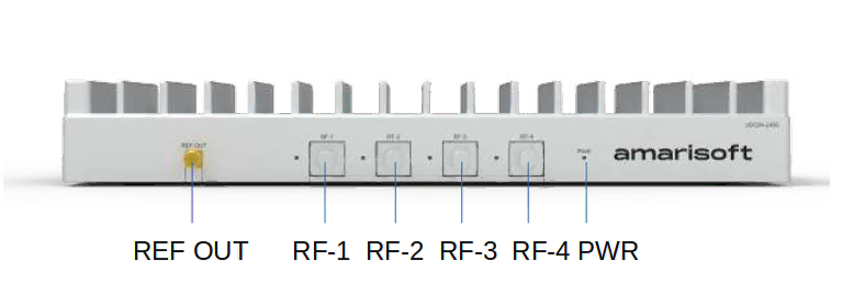
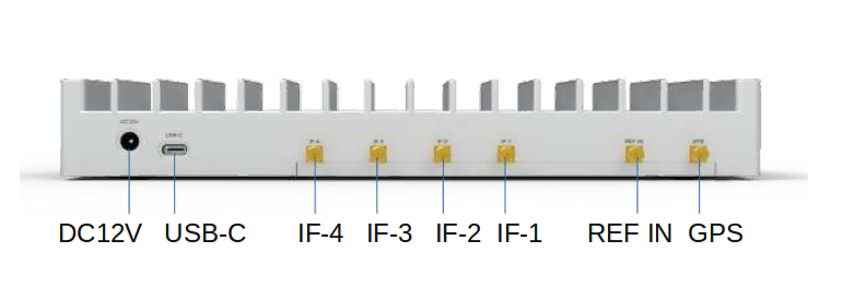
The following images depict the front and rear view of UDCB2.
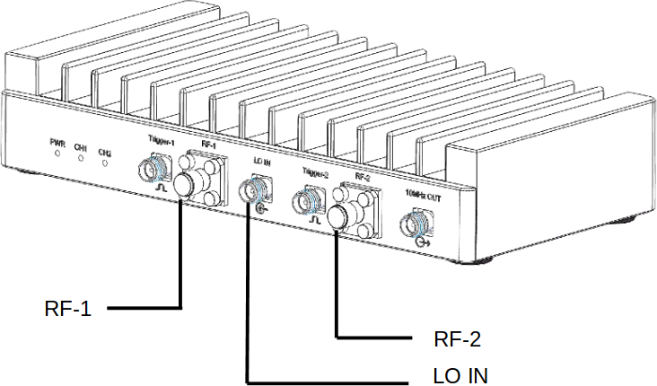
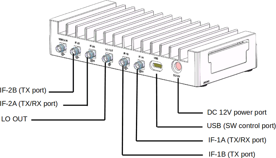
The IF ports correspond to the IF frequency at the input of the UDC and should be connected to the SDR cards according to the use case. The RF ports correpond to the FR2 signal and should be connected to the horn antennas. DC 12V power port is to be conncted to the provided power supply. The USB port is to be connected to the Callbox for UDC configuration. The LO ports are used in case of MIMO to synchronize the UDCs. The following image shows the device connections.
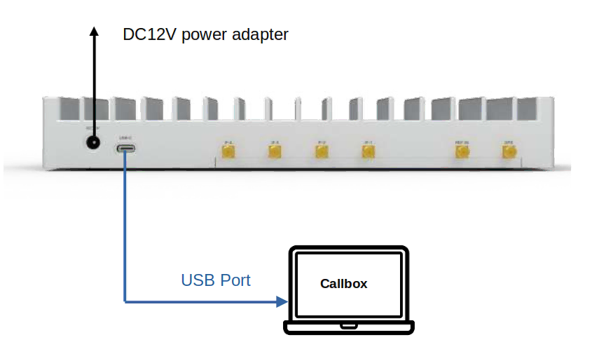
2.1.1 Device Connection
The device connection is depicted below:
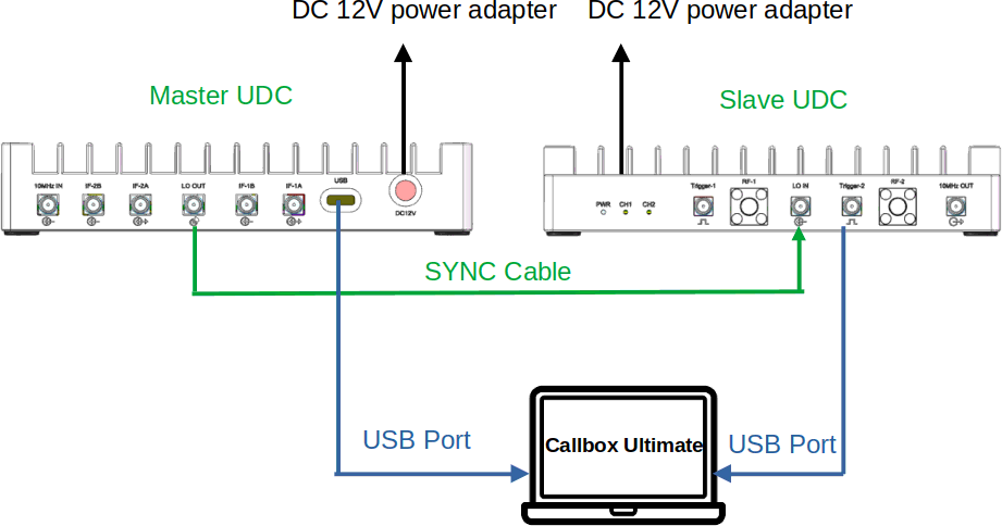
- Connect the power supplies to the DC 12V power port.
- Connect the USB cables to the Callbox. This port is used to configure and control the UDC.
- In case of MIMO, the 2 UDC boxes should be synchronized. This is done by connecting the SYNC cable from LO OUT port of the Master UDC to LO IN port of the slave UDC.
|
The UDCs should be enumerated as |
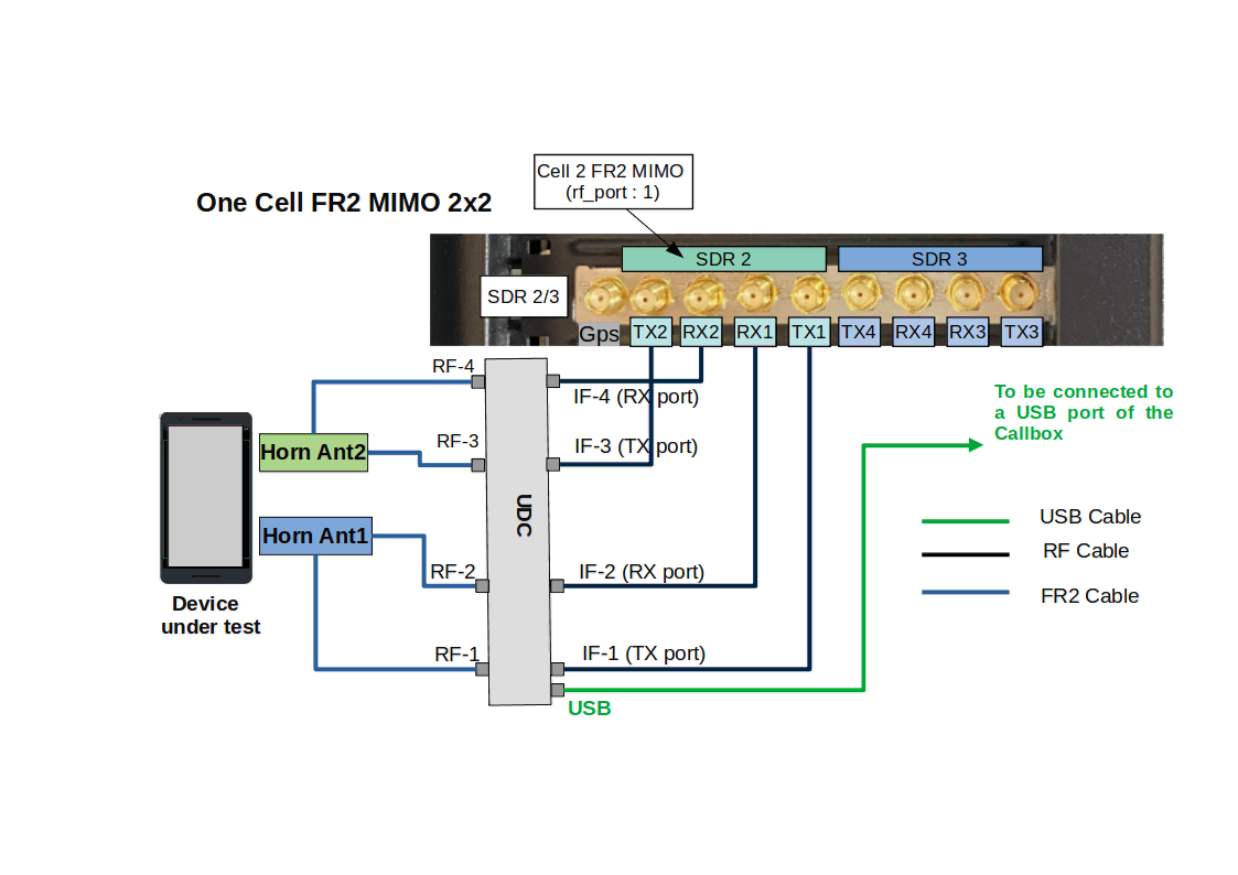
2.1.2 RF Connection Diagram of the UDCB2 for 1 Cell FR2 2x2
The following diagram depicts the cabling for one cell FR2 MIMO 2x2. We assume that SDR0/SDR1 are used for LTE and SDR2 for FR2.
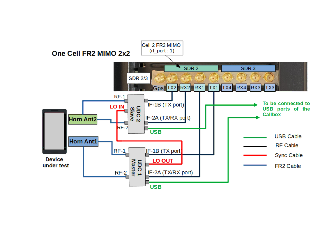
We have assumed that in the config file we have set rx_antenna: "rx", which means RF connection in TDD is the same as for FDD. We have also assumed that the device connection part as explained in the previous section has been done.
- Connect a flexible SMA RF cable to TX1 of the SDR card and the IF-1B port of the master UDC.
- Connect a flexible SMA RF cable to RX1 of the SDR card and the IF-2A port of the master UDC.
- Connect a flexible SMA RF cable to TX2 of the SDR card and the IF-1B port of the slave UDC.
- Connect a flexible SMA RF cable to RX2 of the SDR card and the IF-2A port of the slave UDC.
- Connect a FR2 cable from RF1 and RF2 outputs of each UDC to a horn antenna.
2.1.3 Connection Diagram of the UDCB2 for multiple Cells FR2 2x2
The following diagram depicts the cabling for NSA mode with SDR0/SDR1 used for LTE and SDR2/SDR3 for two cells FR2 MIMO 2x2. These cells could be either configured as 2 different carriers in CA mode or as neighbor cells.
|
Callbox Ultimate and Advanced can only support up to 2 FR2 cells MIMO 2x2. |
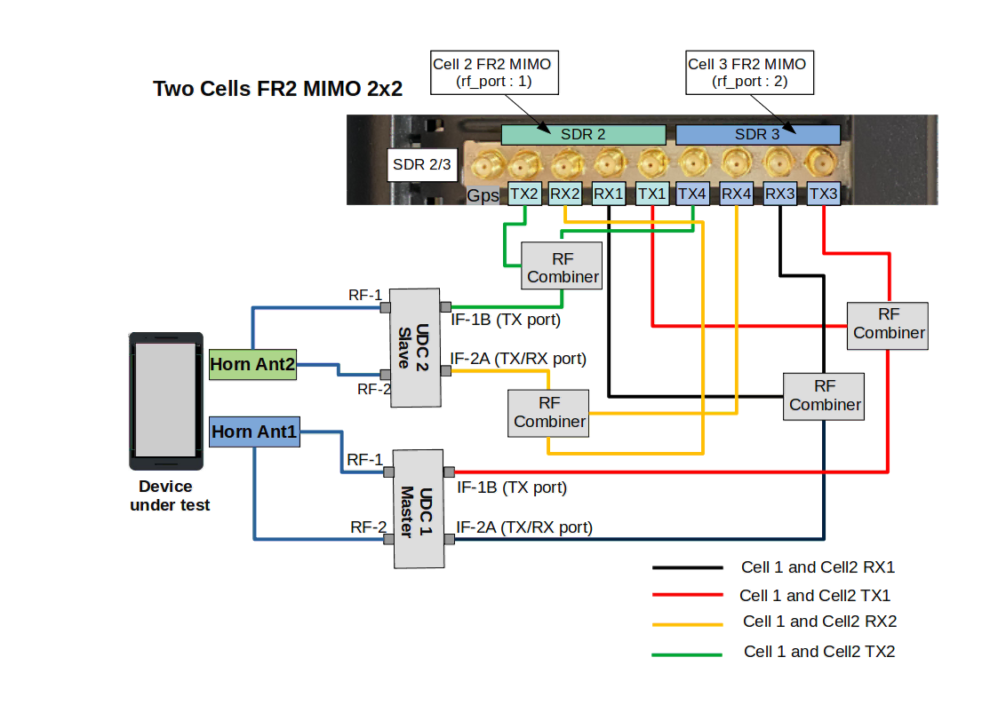
We have assumed that in the config file we have set rx_antenna: "rx", which means RF connection in TDD is the same as for FDD. We have also assumed that the device connection part has been done.
The procedure is exactly as the previous section except that the IF output of each UDC combines the signals coming from each FR2 cell. TX1 of cell 1 and cell 2 are combined and fed into IF-1B port of the master UDC and so on.
2.2 UDCA2 Setup Guide
The following image depicts the UDCA2.
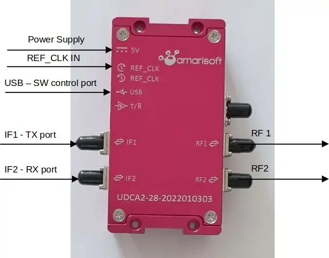
This UDC has 2 IF ports IF1 and IF2, 2 RF ports RF1 and RF2, one USB connector to be connected to the Callbox and one REF IN port to connect to an external 10 MHz clock.
2.2.1 Device Connection
The device connection is depicted below:
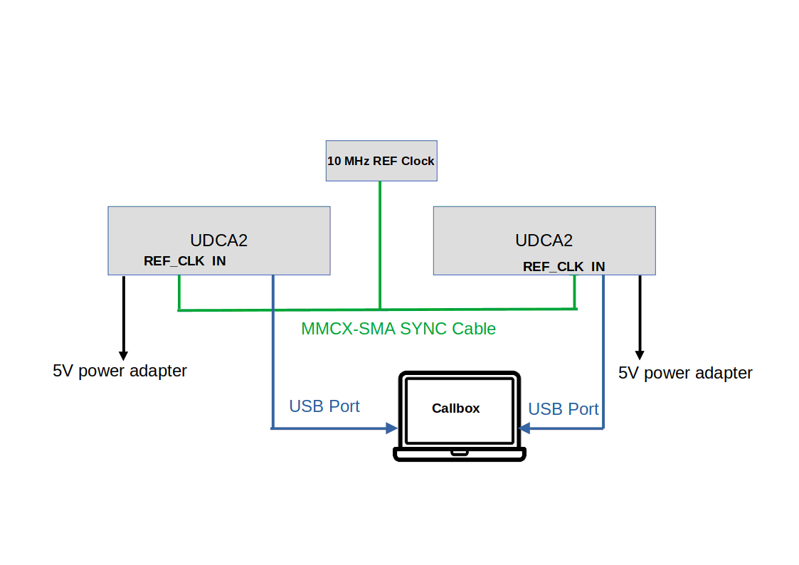
- Connect the power supplies to the 5V power port.
- Connect the USB cables to the Callbox. This port is used to configure and control the UDC.
- In case of MIMO, the 2 UDC boxes should be synchronization. This is done by connecting the MMCX-SMA cable between the external 10 MHz clock and the REF IN connector of each UDC box.
|
The UDCs should be enumerated as |
2.2.2 RF Connection Diagram of the UDCA2 for 1 Cell FR2 2x2
The following diagram depicts the cabling for one cell FR2 MIMO 2x2. We assume that SDR0/SDR1 are used for LTE and SDR2 for FR2.
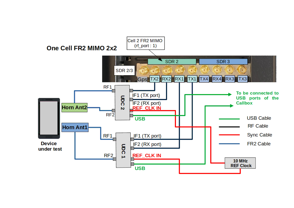
We have assumed that in the config file we have set rx_antenna: "rx", which means RF connection in TDD is the same as for FDD. We have also assumed that the device connection part as explained in the previous section has been done.
The setup of the UDC is as follows:
- Connect a flexible SMA RF cable to TX1 of the SDR card and the IF1 port of the UDC 1.
- Connect a flexible SMA RF cable to RX1 of the SDR card and the IF2 port of the UDC 1.
- Connect a flexible SMA RF cable to TX2 of the SDR card and the IF1 port of the UDC 2.
- Connect a flexible SMA RF cable to RX2 of the SDR card and the IF2 port of the UDC 2.
- Connect a FR2 cable from RF1 and RF2 outputs of each UDC to a horn antenna.
2.2.3 Connection Diagram of the UDCA2 for multiple Cells FR2 2x2
The following diagram depicts the cabling for two cells FR2 MIMO 2x2.
|
Callbox Ultimate and Advanced can only support up to 2 FR2 cells MIMO 2x2. |
The procedure is exactly as the previous section except that the IF output of each UDC combines 1 signal from each FR2 cell. TX1 of cell 1 and cell2 are combined and fed into IF-1B port of the master UDC and so on.

2.3 UDCB4 Setup Guide
The following images depict the front and rear view of UDCB4.
The IF ports correspond to the IF frequency at the input of the UDC and should be connected to the SDR cards according to the use case. The RF ports correpond to the FR2 signal and should be connected to the horn antennas. DC 12V power port is to be conncted to the provided power supply. The USB port is to be connected to the Callbox for UDC configuration.
2.3.1 Device Connection
The device connection is depicted below:
- Connect the power supply to the DC 12V power port.
- Connect the USB cable to the Callbox. This port is used to configure and control the UDC.
|
The UDC should be enumerated as |
2.3.2 RF Connection Diagram of the UDCB4-2430 for 1 Cell FR2 2x2
The following diagram depicts the cabling for one cell FR2 MIMO 2x2. We assume that SDR0/SDR1 are used for LTE and SDR2 for FR2.
We have assumed that in the config file we have set rx_antenna: "rx", which means RF connection in TDD is the same as for FDD. We have also assumed that the device connection part as explained in the previous section has been done.
The setup of the UDC is as follows:
- Connect a flexible SMA RF cable to TX1 of the SDR card and the IF1 port of the UDC.
- Connect a flexible SMA RF cable to RX1 of the SDR card and the IF2 port of the UDC.
- Connect a flexible SMA RF cable to TX2 of the SDR card and the IF3 port of the UDC.
- Connect a flexible SMA RF cable to RX2 of the SDR card and the IF4 port of the UDC.
- Connect a FR2 cable from RF1 and RF2 outputs of each UDC to a horn antenna.
2.3.3 RF Connection Diagram of the UDCB4-3748 for 1 Cell FR2 2x2
The following diagram depicts the cabling for one cell FR2 MIMO 2x2. We assume that SDR0/SDR1 are used for LTE and SDR2 for FR2.
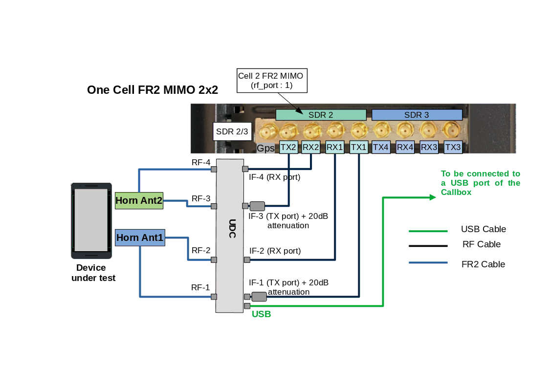
We have assumed that in the config file we have set rx_antenna: "rx", which means RF connection in TDD is the same as for FDD. We have also assumed that the device connection part as explained in the previous section has been done.
The setup of the UDC is as follows:
- Connect a flexible SMA RF cable to TX1 of the SDR card and the IF1 port of the UDC + 20dB attenuation.
- Connect a flexible SMA RF cable to RX1 of the SDR card and the IF2 port of the UDC.
- Connect a flexible SMA RF cable to TX2 of the SDR card and the IF3 port of the UDC + 20dB attenuation.
- Connect a flexible SMA RF cable to RX2 of the SDR card and the IF4 port of the UDC.
- Connect a FR2 cable from RF1 and RF2 outputs of each UDC to a horn antenna.
Due to hardware constraints related to high-frequency signals, the saturation level of the UDCB4-3748 is 20 dB lower than that of the UDCB4-2430. Therefore, adding 20 dB attenuation at the IF TX ports of the UDC is necessary to prevent saturation of the UDCB4-3748. The 20 dB attenuators are included in the UDCB4-3748 package.
2.3.4 Connection Diagram of the UDCB4-2430 for multiple Cells FR2 2x2
The procedure is exactly the same as in the previous section, except that the IF inputs of the UDC are connected to an RF combiner. The TX1 ports from cell 1, cell 2, up to cell 10 are combined and fed into the IF1 port of the UDC. Similarly, the RX1 ports from cell 1, cell 2, up to cell 10 are combined and fed into the IF2 port of the UDC, and so on.
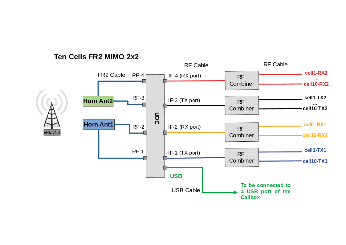
The RX side could be simplified if there is no MIMO in UL by removing the IF4 input. When testing carrier aggregation, usually the UL signal comes only from the primary cell. In this case, the IF3 could be directly connected to the primary cell RX1 port.
2.3.5 Connection Diagram of the UDCB4-3748 for multiple Cells FR2 2x2
The procedure is exactly the same as in the previous section, except that the IF inputs of the UDC are connected to an RF combiner. The TX1 ports from cell 1, cell 2, up to cell 10 are combined and fed into the IF1 port of the UDC. Similarly, the RX1 ports from cell 1, cell 2, up to cell 10 are combined and fed into the IF2 port of the UDC, and so on. Due to hardware constraints related to high-frequency signals, the saturation level of the UDCB4-3748 is 20 dB lower than that of the UDCB4-2430. Therefore, adding 20 dB attenuation at the IF TX ports of the UDC is necessary to prevent saturation of the UDCB4-3748. The 20 dB attenuators are included in the UDCB4-3748 package.
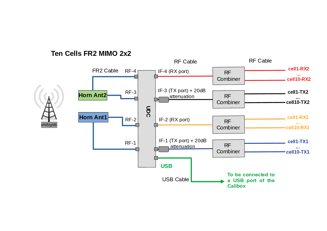
The RX side could be simplified if there is no MIMO in UL by removing the IF4 input. When testing carrier aggregation, usually the UL signal comes only from the primary cell. In this case, the IF3 could be directly connected to the primary cell RX1 port.
3 Configuration Guide
This chapter goes through UDC and gNodeB configuration, made with the script udc-auto-cfg.sh, this new configuration method has been introduced since official release 2024_06_14. The legacy configuration method is still supported for backward compatibility See Annex A. In case of UDC manual configuration, refer to each UDC model user manual.
3.1 Changes from legacy configuration
In the legacy configuration method, the user needs to configure the parameters related to the FR2 setup as tx_gain, rf_dl_freq, rf_ul_freq, ss_pbch_block_power. A proper configuration of these parameters require a good knowledge of the UDC device type involved in the set-up, thus the difficulty of tuning the values without incurring in UDC saturations or not efficient LO/IF frequecy combinations. The udc-auto-cfg.sh script aims to simplify the user experience for the FR2 set-up by optimising the following FR2 configuration parameters:
- IF frequency. It selects the best SDR frequency based on SDR performances and UDC specification
- LO frequency. It selects and configures the correct LO frequency for the UDC, based on the output FR2 RF frequency and the selected SDR IF frequency
-
tx_gainof eachrf_portrelated to FR2 cells, to avoid the UDC IF port saturation -
ss-PBCH-BlockPowerbased on SDR TX power and UDC power amplification.ss-PBCH-BlockPoweris used by the UE to estimate correct pathloss.
3.2 UDC B2 Configuration
The usage of script udc-auto-cfg.sh relies on the newly introduced udc_ports array which is composed by one or multiple objects. Each object contains the configurations of the UDC devices involved in the FR2 set-up as well as the call to udc-auto-cfg.sh script. Each udc_ports object contains the following configurable parameters:
-
cmd: path to the script for the UDC configuration. The default script path isenb/config -
args: string of UDC configuration parameters. Each parameter is separated by semicolon. The configurable parameters are:- UDC enumeration, mandatory. It specifies how the UDC has been mounted at Linux level. UDCB2 are mounted as /dev/ttyUSBx.
- UDC clock, optional, possible values are detailed in the dedicated subsections See UDC B2 args values for
udc-auto-cfg.sh - UDC tx ports, optional, possible values are detailed in the dedicated subsections See UDC B2 args values for
udc-auto-cfg.sh - UDC rx ports, optional, possible values are detailed in the dedicated subsections See UDC B2 args values for
udc-auto-cfg.sh
-
lo_freq: optional float to specify the UDC LO frequency in MHz to be configured. If not present, it will be automatically computed by theudc-auto-cfg.shrespecting the SDR IF suitable frequency range and UDC datasheet.
This is an example of pseudo code to understand the usage of the newly introduced udc_ports array. The example uses a couple of UDC B2 for a single FR2 cell MIMO 2x2. The UDCs are connected to sdrX.
  rf_driver: {
        name: "sdr",
        args: "dev0=/dev/sdrX",
        rx_antenna: "rx",
  },
#if FR2 == 1
  udc_ports: [
  {
    /* this is udc port index 0*/
    args: "/dev/ttyUSBx;/dev/ttyUSBy",
    cmd: "udc-auto-cfg.sh",
  },
  ],
#endif

  rf_ports: [
  {
     #if FR2
       /* rf port related to FR2 cell => indicate corresponding udc port index
       udc_port: 0,
       tx_power_offset:IF_ATTENUATION,
     #endif
  },
  ],
To compute the tx_power_offset, See Measure tx_power_offset.
3.2.1 UDC B2 args values for udc-auto-cfg.sh
This section specifies how to configure the parameter args for UDC B2. The only mandatory string parameter is the UDC device enumeration, it specifies how the UDC has been mounted at Linux level. UDCB2 is mounted as /dev/ttyUSBx. The other string parameters are optional, if not specified, they are configured with the default value. For the default set-up reference cabling See RF Connection Diagram of the UDCB2 for 1 Cell FR2 2x2 and See Connection Diagram of the UDCB2 for multiple Cells FR2 2x2
When using the UDC B2 in default set-up cabling it is just required to specify in args the device enumeration, while the optional parameters clock,tx,rx will be set with the default values. Example of configuration line:
args:"/dev/ttyUSB0;/dev/ttyUSB1"
|
In a UDC set-up involving two UDC B2 the UDC B2 master is UDC providing the clock through the port LO_OUT while the UDC B2 slave is UDC receiving the clock from the port LO_IN |
The values accepted as args input for UDC B2 are:
clock:internalroot.internaluse the internal UDC B2 clock
externalroot.externaluse the clock coming from the LO_IN port of the UDC B2
defaultroot.defaultuse the
internalclock for the UDC B2 master and theexternalfor the UDC B2 slave. If only one UDC B2 in the setup useinternal
tx:1root.1use TRX port IF1A in TX mode
2root.2use TX port IF1B
3root.3use TRX port IF2A in TX mode
4root.4use TX port IF2B
defaultroot.defaultuse value 2, TX port IF1B, as per default cabling
rx1root.1use TRX port IF1A in RX mode
3root.3use TRX port IF2A in RX mode
defaultroot.defaultuses value 3, TRX port IF2A in RX mode, as per default cabling
Any different usage of args input parameters with respect to the illustrated default case, shall match the physical cabling in the set-up. It is up to the user to verify it prior to testing.
Example of a set-up where UDCs have inverted TX/RX ports from defualt values. In this case IF2B is used as TX port and IF1A as RX port, /dev/ttyUSB0 remains the master and /dev/ttyUSB1 remains the slave:
args:"/dev/ttyUSB0;clock=internal;tx=4;rx=1;/dev/ttyUSB1;clock=external;tx=4;rx=1"
|
The default UDC configuration script assumes that the first /dev/ttyUSBx specified in ll /dev/ttyUSB* |
3.2.2 UDC B2 SA Configuration with one FR2 cell
The example below shows the usage of the udc-auto-cfg.sh for UDCB2. In the example, there are 2 UDCs connected to SDR0 of the Callbox to provide a single cell FR2 SA MIMO 2x2. The first UDC(master) is identified as /dev/ttyUSB0 and the second one(slave) as /dev/ttyUSB1.
  rf_driver: {
        name: "sdr",
        args: "dev0=/dev/sdr0",
        rx_antenna: "rx",
  },
The udc_ports contains the configuration for the udc port related to the UDCB2 setup. Both the UDCs /dev/ttyUSB0(master) and /dev/ttyUSB1(slave) are configured in the same udc-auto-cfg.sh call.
In the args when the UDC device enumeration is the only specified parameter, it is assumed that the other optional parameters (clock;tx;rx) take the default value.
#if FR2 == 1
  udc_ports: [
  {
    args: "/dev/ttyUSB0;/dev/ttyUSB1",
    cmd: "udc-auto-cfg.sh",
  },
  ],
#endif
The rf port related to the FR2 cell needs to specify which udc_port is used. To compute the tx_power_offset, See Measure tx_power_offset
  rf_ports: [
  {
     #if FR2
       udc_port: 0,
       tx_power_offset:IF_ATTENUATION,
     #endif
  },
  ],
3.2.3 UDC B2 NSA Configuration with one FR2 cell
This section gives an example of udc_ports and rf_ports configurtion in the case of NSA configuration with a single FR2 cell.
In the example the SDR0 is used by the LTE cell while the UDC B2 are connected to SDR1 of the Callbox to provide the FR2 MIMO 2x2 cell. The first UDC(master) is identified as /dev/ttyUSB0 and the second one(slave) as /dev/ttyUSB1.
  rf_driver: {
        name: "sdr",
        args: "dev0=/dev/sdr0,dev1=/dev/sdr1",
        rx_antenna: "rx",
  },
#if FR2 == 1
  udc_ports: [
  {
    args: "/dev/ttyUSB0;/dev/ttyUSB1",
    cmd: "udc-auto-cfg.sh",
  },
  ],
#endif
  rf_ports: [
    {
       /* RF port for the LTE cell */
    },
    {
        /* RF port for the NR cell */
#if FR2
       udc_port: 0,
       tx_power_offset:IF_ATTENUATION,
#endif
    },
  ],
To compute the tx_power_offset, See Measure tx_power_offset
3.2.4 UDC B2 NSA Configuration with Multiple FR2 cells
This section gives an example of udc_ports and rf_ports configurtion in the case of NSA configuration with two aggregated FR2 cells.
In the example the SDR0 is used by the LTE cell while the UDC is connected though a combiner to SDR2 and SDR3 of the Callbox to provide the FR2 MIMO 2x2 cells. The first UDC(master) is identified as /dev/ttyUSB0 and the second one(slave) as /dev/ttyUSB1.
  rf_driver: {
        name: "sdr",
        args: "dev0=/dev/sdr0,dev1=/dev/sdr2,dev2=/dev/sdr3",
        rx_antenna: "rx",
  },
#if FR2 == 1
  udc_ports: [
  {
    args: "/dev/ttyUSB0;/dev/ttyUSB1",
    cmd: "udc-auto-cfg.sh",
  },
  ],
#endif
  rf_ports: [
    {
       /* RF port for the LTE cell */
    },
    {
        /* RF port for the NR cell */
#if FR2
       udc_port: 0,
       tx_power_offset:IF_ATTENUATION,
#endif
    },
    {
        /* RF port for the NR cell */
#if FR2
       udc_port: 0,
       tx_power_offset:IF_ATTENUATION,
#endif
    },
  ],
Both the rf_ports related to the FR2 cells are specifying the same udc_port since they are aggregated and they will use the same UDC device for the RF up/down conversion. To compute the tx_power_offset, See Measure tx_power_offset.
3.3 UDC A2 configuration
The usage of script udc-auto-cfg.sh relies on the newly introduced udc_ports array which is composed by one or multiple objects. Each object contains the configurations of the UDC devices involved in the FR2 set-up as well as the call to udc-auto-cfg.sh script. Each udc_ports object contains the following configurable parameters:
-
cmd: path to the script for the UDC configuration. The default script path isenb/config -
args: string of UDC configuration parameters. Each parameter is separated by semicolon. The configurable parameters are:- UDC enumeration, mandatory. It specifies how the UDC has been mounted at Linux level. UDCA2 are mounted as /dev/ttyACMx.
- UDC clock, optional, possible values are detailed in the dedicated subsections See UDC A2 args values for
udc-auto-cfg.sh - UDC tx ports, optional, possible values are detailed in the dedicated subsections See UDC A2 args values for
udc-auto-cfg.sh - UDC rx ports, optional, possible values are detailed in the dedicated subsections See UDC A2 args values for
udc-auto-cfg.sh
-
lo_freq: optional float to specify the UDC LO frequency in MHz to be configured. If not present, it will be automatically computed by theudc-auto-cfg.shrespecting the SDR IF suitable frequency range and UDC datasheet.
This is an example of pseudo code to understand the usage of the newly introduced udc_ports array. The example uses a couple of UDC A2 for a single FR2 cell MIMO 2x2. The UDCs are connected to sdrX.
  rf_driver: {
        name: "sdr",
        args: "dev0=/dev/sdrX",
        rx_antenna: "rx",
  },
#if FR2 == 1
  udc_ports: [
  {
    /* this is udc port 0*/
    args: "/dev/ttyACMx;/dev/ttyACMy",
    cmd: "udc-auto-cfg.sh",
  },
  ],
#endif

  rf_ports: [
  {
     #if FR2
       /* rf port related to FR2 cell => indicate corresponding udc port index
       udc_port: 0,
       tx_power_offset:IF_ATTENUATION,
     #endif
  },
  ],
To compute the tx_power_offset, See Measure tx_power_offset.
3.3.1 UDC A2 args values for udc-auto-cfg.sh
This section specifies how to configure the parameter args for UDC A2. The only mandatory string parameter is the UDC device enumeration, it specifies how the UDC has been mounted at Linux level. UDCA2 is mounted as /dev/ttyACMx. The other string parameters are optional, if not specified, they are configured with the default value. For the default set-up reference cabling See RF Connection Diagram of the UDCA2 for 1 Cell FR2 2x2 and See Connection Diagram of the UDCA2 for multiple Cells FR2 2x2
When using the UDC A2 in default set-up cabling it is just required to specify in args the device enumeration, while the optional parameters clock,tx,rx will be set with the default values. Example of configuration line:
args:"/dev/ttyACM0;/dev/ttyACM1"
The values accepted as args input for UDC A2 are:
clock:any clock configuration is ignored since for UDC A2 there is no command to set the clock. To work it requires always the 10MHz clock source as depicted in the default cabling connection.
tx:1root.1use port IF1
2root.2use port IF2
defaultroot.defaultuse value 1, IF1 port as per default cabling
rx1root.1use port IF1
2root.2use port IF2
defaultroot.defaultuse value 2, IF2 port as per default cabling
Any different usage of args input parameters with respect to the illustrated default case, shall match the physical cabling in the set-up. It is up to the user to verify it prior to testing.
Example of a set-up where UDCs have inverted ports from defualt values, in this case the TX port for both the UDCs is IF2 while the RX port is IF1:
args:"/dev/ttyACM0;tx=2;rx=1;/dev/ttyACM1;tx=2;rx=1"
|
To assure the correct device enumeration, special attention shall be put when plugging in the USB cables. After a machine reboot, the device enumeration could have changed, therefore repeat the USB cable plug procedure. To double check the correct device enumeration it is possible to use, after each USB plug, the following Linux command: ll /dev/ttyACM* |
3.3.2 UDC A2 SA Configuration with one FR2 cell
The example below shows the usage of the udc-auto-cfg.sh for UDCA2. In the example, there are 2 UDCs connected to SDR0 of the Callbox to provide a single cell FR2 SA MIMO 2x2. The first UDC is identified as /dev/ttyACM0 and the second one as /dev/ttyACM1.
  rf_driver: {
        name: "sdr",
        args: "dev0=/dev/sdr0",
        rx_antenna: "rx",
  },
The udc_ports contains the configuration for the udc port related to the UDCA2 setup. Both the UDCs /dev/ttyACM0 and /dev/ttyACM1 are configured in the same udc-auto-cfg.sh call.
In the args when the UDC device enumeration is the only specified parameter, it is assumed that the other optional parameters (clock;tx;rx) take the default value.
#if FR2 == 1
  udc_ports: [
  {
    args: "/dev/ttyACM0;/dev/ttyACM1",
    cmd: "udc-auto-cfg.sh",
  },
  ],
#endif
The rf port related to the FR2 cell needs to specify which udc_port is used. To compute the tx_power_offset refer to See Measure tx_power_offset
  rf_ports: [
  {
     #if FR2
       udc_port: 0,
       tx_power_offset:IF_ATTENUATION,
     #endif
  },
  ],
3.3.3 UDC A2 NSA Configuration with one FR2 cell
This section gives an example of udc_ports and rf_ports configurtion in the case of NSA configuration with a single FR2 cell.
In the example the SDR0 is used by the LTE cell while the UDC is connected to SDR1 of the Callbox to provide the FR2 MIMO 2x2 cell. The first UDC is identified as /dev/ttyACM0 and the second one as /dev/ttyACM1.
  rf_driver: {
        name: "sdr",
        args: "dev0=/dev/sdr0,dev1=/dev/sdr1",
        rx_antenna: "rx",
  },
#if FR2 == 1
  udc_ports: [
  {
    args: "/dev/ttyACM0;/dev/ttyACM1",
    cmd: "udc-auto-cfg.sh",
  },
  ],
#endif
  rf_ports: [
    {
       /* RF port for the LTE cell */
    },
    {
        /* RF port for the NR cell */
#if FR2
       udc_port: 0,
       tx_power_offset:IF_ATTENUATION,
#endif
    },
  ],
To compute the tx_power_offset refer to See Measure tx_power_offset.
3.3.4 UDC A2 NSA Configuration with Multiple FR2 cells
This section gives an example of udc_ports and rf_ports configurtion in the case of NSA configuration with two aggregated FR2 cells.
In the example the SDR0 is used by the LTE cell while the UDC is connected though a combiner to SDR2 and SDR3 of the Callbox to provide the FR2 MIMO 2x2 cells. The first UDC is identified as /dev/ttyACM0 and the second one as /dev/ttyACM1.
  rf_driver: {
        name: "sdr",
        args: "dev0=/dev/sdr0,dev1=/dev/sdr2,dev2=/dev/sdr3",
        rx_antenna: "rx",
  },
#if FR2 == 1
  udc_ports: [
  {
    args: "/dev/ttyACM0;/dev/ttyACM1",
    cmd: "udc-auto-cfg.sh",
  },
  ],
#endif
  rf_ports: [
    {
       /* RF port for the LTE cell */
    },
    {
        /* RF port for the NR cell */
#if FR2
       udc_port: 0,
       tx_power_offset:IF_ATTENUATION,
#endif
    },
    {
        /* RF port for the NR cell */
#if FR2
       udc_port: 0,
       tx_power_offset:IF_ATTENUATION,
#endif
    },
  ],
Both the rf_ports related to the FR2 cells are specifying the same udc_port since they are aggregated and they will use the same UDC device for the RF up/down conversion. To compute the tx_power_offset refer to See Measure tx_power_offset.
3.4 UDC B4 configuration
The usage of script udc-auto-cfg.sh relies on the newly introduced udc_ports array which is composed by one or multiple objects. Each object contains the configurations of the UDC devices involved in the FR2 set-up as well as the call to udc-auto-cfg.sh script. Each udc_ports object contains the following configurable parameters:
-
cmd: path to the script for the UDC configuration. The default script path isenb/config -
args: string of UDC configuration parameters. Each parameter is separated by semicolon. The configurable parameters are:- UDC enumeration, mandatory. It specifies how the UDC has been mounted at Linux level. UDCB4 are mounted as /dev/ttyUSBx.
- UDC clock, optional, possible values are detailed in the dedicated subsections See UDC B4 args values for
udc-auto-cfg.sh - UDC tx ports, optional, possible values are detailed in the dedicated subsections See UDC B4 args values for
udc-auto-cfg.sh - UDC rx ports, optional, possible values are detailed in the dedicated subsections See UDC B4 args values for
udc-auto-cfg.sh
-
lo_freq: optional float to specify the UDC LO frequency in MHz to be configured. If not present, it will be automatically computed by theudc-auto-cfg.shrespecting the SDR IF suitable frequency range and UDC datasheet.
This is an example of pseudo code to understand the usage of the newly introduced udc_ports array. The example uses a UDC B4 for a single FR2 cell MIMO 2x2. The UDC is connected to sdrX.
  rf_driver: {
        name: "sdr",
        args: "dev0=/dev/sdrX",
        rx_antenna: "rx",
  },
#if FR2 == 1
  udc_ports: [
  {
    /* this is udc port 0*/
    args: "/dev/ttyUSBx",
    cmd: "udc-auto-cfg.sh",
  },
  ],
#endif

  rf_ports: [
  {
     #if FR2
       /* rf port related to FR2 cell => indicate corresponding udc port index
       udc_port: 0,
       tx_power_offset:IF_ATTENUATION,
     #endif
  },
  ],
To compute the tx_power_offset, See Measure tx_power_offset.
3.4.1 UDC B4 args values for udc-auto-cfg.sh
This section specifies how to configure the parameter args for UDC B4. The only mandatory string parameter is the UDC device enumeration, it specifies how the UDC has been mounted at Linux level. UDCB4 is mounted as /dev/ttyUSBx. The other string parameters are optional, if not specified, they are configured with the default value. For the default set-up reference cabling See RF Connection Diagram of the UDCB4-2430 for 1 Cell FR2 2x2 ; See Connection Diagram of the UDCB4-2430 for multiple Cells FR2 2x2 ; See RF Connection Diagram of the UDCB4-3748 for 1 Cell FR2 2x2and See Connection Diagram of the UDCB4-3748 for multiple Cells FR2 2x2
When using the UDC B4 in default set-up cabling it is just required to specify in args the device enumeration, while the optional parameters clock,tx,rx will be set with the default values. Example of configuration line:
args:"/dev/ttyUSB0"
The values accepted as args input for UDC B4 are:
clock:internalroot.internaluse the internal UDC B4 clock
externalroot.externaluse the clock coming from the REF_IN port of the UDC B4, this must be connected to a 10MHz reference clock source
gpsroot.gpsuse the clock coming from the GPS port of the UDC B4, this must be connected to a GPS clock source
defaultroot.defaultuse the
internalclock of the UDC B4
tx:1root.1use port IF1
2root.2use port IF2
3root.3use port IF3
4root.4use port IF4
defaultroot.defaultuse value 1,3 indicating IF1 and IF3 ports as per default cabling
rx1root.1use port IF1
2root.2use port IF2
3root.3use port IF3
4root.4use port IF4
defaultroot.defaultuse value 2,4 indicating IF2 and IF4 ports as per default cabling
Any different usage of args input parameters with respect to the illustrated default case, shall match the physical cabling in the set-up. It is up to the user to verify it prior to testing.
Example of a set-up where UDCs have inverted ports from defualt values and a different clock source. UDC B4-2430 TX ports are 2,4 and RX ports 1,3. UDC B4-2430 using 10MHz clock source.
args:"/dev/ttyUSB0;clock=external;tx=2,4;rx=1,3"
|
To assure the correct device enumeration, special attention shall be put when plugging in the USB cable. After a machine reboot, the device enumeration could have changed, therefore repeat the USB cable plug procedure. To double check the correct device enumeration it is possible to use, after each USB plug, the following Linux command: ll /dev/ttyUSB* |
3.4.2 UDC B4 SA Configuration with one FR2 cell
The example below shows the usage of the udc-auto-cfg.sh for UDCB4. In the example there is one UDC connected to SDR0 of the Callbox to provide a single cell FR2 SA MIMO 2x2. The UDC is identified as /dev/ttyUSB0.
  rf_driver: {
        name: "sdr",
        args: "dev0=/dev/sdr0",
        rx_antenna: "rx",
  },
The udc_ports contains the configuration for the udc port related to the UDCB4. In the args when the UDC device enumeration is the only specified parameter, it is assumed that the other optional parameters (clock;tx;rx) take the default value.
#if FR2 == 1
  udc_ports: [
  {
    args: "/dev/ttyUSB0",
    cmd: "udc-auto-cfg.sh",
  },
  ],
#endif
The rf port related to the FR2 cell needs to specify which udc_port is used. To compute the tx_power_offset refer to See Measure tx_power_offset.
  rf_ports: [
  {
     #if FR2
       udc_port: 0,
       tx_power_offset:IF_ATTENUATION,
     #endif
  },
  ],
3.4.3 UDC B4 NSA Configuration with one FR2 cell
This section gives an example of udc_ports and rf_ports configurtion in the case of NSA configuration with a single FR2 cell.
In the example the SDR0 is used by the LTE cell while the UDC is connected to SDR1 of the Callbox to provide the FR2 MIMO 2x2 cell. It is assumed the usage of UDCB4 identified as /dev/ttyUSB0.
  rf_driver: {
        name: "sdr",
        args: "dev0=/dev/sdr0,dev1=/dev/sdr1",
        rx_antenna: "rx",
  },
#if FR2 == 1
  udc_ports: [
  {
    args: "/dev/ttyUSB0",
    cmd: "udc-auto-cfg.sh",
  },
  ],
#endif
  rf_ports: [
    {
       /* RF port for the LTE cell */
    },
    {
        /* RF port for the NR cell */
#if FR2
       udc_port: 0,
       tx_power_offset:IF_ATTENUATION,
#endif
    },
  ],
To compute the tx_power_offset refer to See Measure tx_power_offset
3.4.4 UDC B4 NSA Configuration with Multiple FR2 cells
This section gives an example of udc_ports and rf_ports configurtion in the case of NSA configuration with two aggregated FR2 cells.
In the example the SDR0 is used by the LTE cell while the UDC is connected though a combiner to SDR2 and SDR3 of the Callbox to provide the FR2 MIMO 2x2 cells. It is assumed the usage of UDCB4 identified as /dev/ttyUSB0.
  rf_driver: {
        name: "sdr",
        args: "dev0=/dev/sdr0,dev1=/dev/sdr2,dev2=/dev/sdr3",
        rx_antenna: "rx",
  },
#if FR2 == 1
  udc_ports: [
  {
    args: "/dev/ttyUSB0",
    cmd: "udc-auto-cfg.sh",
  },
  ],
#endif
  rf_ports: [
    {
       /* RF port for the LTE cell */
    },
    {
        /* RF port for the NR cell */
#if FR2
       udc_port: 0,
       tx_power_offset:IF_ATTENUATION,
#endif
    },
    {
        /* RF port for the NR cell */
#if FR2
       udc_port: 0,
       tx_power_offset:IF_ATTENUATION,
#endif
    },
  ],
Both the rf_ports related to the FR2 cells are specifying the same udc_port since they are aggregated and they will use the same UDC device for the RF up/down conversion. To compute the tx_power_offset refer to See Measure tx_power_offset.
3.5 Measure tx_power_offset
When the udc_port is referenced in a rf port, it is possible to specify the IF_ATTENUATION using the parameter tx_power_offset. This quantity is important for the computation of the maximum tx_gain applicable at each rf port to avoid UDC saturation. The IF_ATTENUATION corresponds to the amount of attenuation between the SDR TX port and the UDC IF port. The default value is 0, in case of aggregated cells using a combiner the attenuation is computed as -10*log10(NB COMBINER PORTS), eventual additional attenuators need to be added to this value.
- Example of a UDC connected directly to the SDR without any attenuation or combiner between SDR and UDC IF port:
tx_power_offset:0
- Example of a UDC connected directly to the SDR with 20dB physical attenuation between SDR and UDC IF port:
tx_power_offset:-20
- Example of a UDC connected to the SDR in a setup with 8 port combiner:
tx_power_offset:-9
- Example of a UDC connected to the SDR in a setup with 12 port combiner:
tx_power_offset:-11
- Example of a UDC connected to the SDR in a setup with 12 port combiner and additional 20dB physical attenuation:
tx_power_offset:-31
|
Due to hardware constraints related to high-frequency signals, the saturation level of the UDCB4-3748 is 20 dB lower than that of the UDCB4-2430. Therefore, adding 20 dB attenuation at the IF TX ports of the UDC is necessary to prevent saturation of the UDCB4-3748. The 20 dB attenuation shall be considered in the IF_ATTENUATION parameter. |
3.6 Debug
To enable the udc-auto-cfg.sh debug logs it is required to enable the trx log level in debug mode in the configuration file. Example:
log_options: "all.level=error,all.max_size=0,nas.level=debug,nas.max_size=1,
s1ap.level=debug,s1ap.max_size=1,x2ap.level=debug,x2ap.max_size=1,
rrc.level=debug,rrc.max_size=1,trx.level=debug,trx.max_size=1",
3.7 Tested FR2 UEs
Following UEs have been tested in FR2:
- Samsung Galaxy S20+ 5G SM-G986U1 smartphone in NSA 2CC FR2
- Quectel RM510Q-GL 5G NR mmWave module, M.2 form factor, in NSA 8CC FR2
- Simcom SIM8380G-M2 Sub6 + mmW Module, M.2 form factor, in NSA 8CC FR2
- Google Pixel 8 Pro G1MNW, in NSA and NR-DC 1CC FR2
4 Annex A
This annex describes the legacy UDC and gNodeB configuration, for backward compatibility with the configuration method described in See Configuration Guide
4.1 Legacy UDC Configuration
UDCs should be configured first for the target output frequency. This configuration could be done automatically by adding parameters config_script and config_script_params inside the rf_driver object. For manual configuration, you can refer to the user manual of each UDC.
-
config_script:
This parameter specifies the script to run in order to configure the UDC. The script is called with the parameters specified inconfig_script_paramsfor each SDR defined in args. The default path is the current directry. -
config_script_params:
This field specifies the parameters to be passed to the configuration script defined inconfig_script. If there are multiple up down converters connected to different SDR cards, then the parameters to be passed to each up down converter box should be separated by a ;. The list of parameters are:-
UDC_TYPE: This field specifies the UDC type to be used. It could be B2 for UDCB2 or A2 for UDCA2 or B4 for UDCB4. -
UDC_DEV: This field specifies how the UDC has been mounted at Linux level. UDCB2 and UDCB4 are mounted as/dev/ttyUSBxand UDCA2 as/dev/ttyACMx. -
SDR_NUM: This field is the SDR number connected to the UDC. -
OUT_FREQ: This field corresponds to the FR2 frequency in Hz at the output of the UDC.
-
4.1.1 Legacy UDCB2 Configuration
The example below shows the use of these 2 parameters for UDCB2. There are 2 UDCs connected to SDR2 of the Calllbox to provide MIMO 2x2. The output frequency is 28.00008 GHz. The first UDC is identified as /dev/ttyUSB0 and the second one as /dev/ttyUSB1.
rf_driver: {
    name: "sdr",

    /* list of devices. 'dev0' is always the master. */
    args: "dev0=/dev/sdr0,dev1=/dev/sdr1,dev2=/dev/sdr2",

    /* TDD: force the RX antenna on the RX connector */
    rx_antenna: "rx",

    // sync: "gps",
    config_script: "rf_driver/udc-cfg.sh",
    config_script_params: "UDC_TYPE=B2 UDC_DEV=/dev/ttyUSB0 SDR_NUM=2
    OUT_FREQ=28000080000; UDC_TYPE=B2 UDC_DEV=/dev/ttyUSB1 SDR_NUM=2 OUT_FREQ=28000080000;",
},
|
UDC B2 LO frequency is in GHz. When setting the OUT_FREQ, special attention should be made to avoid a floating point LO which is rejected by the UDC. In the above example with an OUT_FREQ of 28000080000 Hz, the IF_FREQ should be set to 3000.08 MHz in order to have a LO FREQ of 25 GHz. |
4.1.2 Legacy UDCA2 Configuration
The example below shows the use of these 2 parameters for UDCA2. There are 2 UDCs connected to SDR2 of the Calllbox to provide MIMO 2x2. The output frequency is 28.00008 GHz. The first UDC is identified as /dev/ttyACM0 and the second one as /dev/ttyACM1.
rf_driver: {
    name: "sdr",

    /* list of devices. 'dev0' is always the master. */
    args: "dev0=/dev/sdr0,dev1=/dev/sdr1,dev2=/dev/sdr2",

    /* TDD: force the RX antenna on the RX connector */
    rx_antenna: "rx",

    // sync: "gps",
    config_script: "rf_driver/udc-cfg.sh",
    config_script_params: "UDC_TYPE=A2 UDC_DEV=/dev/ttyACM0 SDR_NUM=2
    OUT_FREQ=28000080000; UDC_TYPE=A2 UDC_DEV=/dev/ttyACM1 SDR_NUM=2 OUT_FREQ=28000080000;",
},
|
UDC A2 LO frequency is in MHz. When setting the OUT_FREQ, special attention should be made to avoid a floating point LO which is rejected by the UDC. In the above example with an OUT_FREQ of 28000080000 Hz, the IF_FREQ should be set to 3000.08 Hz in order to have a LO FREQ of 25000 MHz. |
4.1.3 Legacy UDCB4 Configuration
The example below shows the use of these 2 parameters for UDCB4. There is 1 single UDC connected to SDR2 of the Callbox to provide MIMO 2x2. The output frequency is 28.00008 GHz. The UDC is identified as /dev/ttyUSB0.
rf_driver: {
    name: "sdr",

    /* list of devices. 'dev0' is always the master. */
    args: "dev0=/dev/sdr0,dev1=/dev/sdr1,dev2=/dev/sdr2",

    /* TDD: force the RX antenna on the RX connector */
    rx_antenna: "rx",

    // sync: "gps",
    config_script: "rf_driver/udc-cfg.sh",
    config_script_params: "UDC_TYPE=B4 UDC_DEV=/dev/ttyUSB0 SDR_NUM=2 OUT_FREQ=28000080000;",
},
|
UDC B4 LO frequency could be set in GHz, MHz and KHz. When setting the OUT_FREQ, special attention should be made to avoid a floating point LO which is rejected by the UDC. |
4.2 Legacy gNodeB Configuration
4.2.1 Legacy NSA Configuration with one FR2 cell
gnb-nsa.cfg could be used for NSA mmwave testing with FR2 flag enabled. This file configures one LTE cell and one FR2 cell.
The IF frequency is pre-configured within the gNodeB config file. Its value is set to the frequency 3 GHz as it is within the range of frequencies giving the best signal EVM at the output of the UDC. It is recommended to use an IF between 2 GHz and 4 GHz.
The following extract shows the setting of the IF frequency inside this configuration file for an output FR2 frequency of 28000.08 MHz. The parameters rf_dl_freq and rf_ul_freq inside the rf_ports object set the IF frequencies in DL and UL.
rf_ports: [
    {
#if FR2
      /* an external frequency translator must be used */
      rf_dl_freq: 3000.08, /* MHz */
      rf_ul_freq: 3000.08, /* MHz */
#endif
    },
  ],
These parameters are to be added to the rf_ports list in the position corresponding to the rf_port of the FR2 cell.
The parameter rx_to_tx_latency could also be used to increase the data rate in FR2. This parameter defines the minimum allowed latency in slots between RX and TX. If the latency is too high, the gNB scheduler may not be able to use all the PDSCH transmission occasions with subcarrier spacings larger or equal to 30 kHz. Typically for the default value of 4 msec and 120 KHz subcarrier spacing in FR2, not all PDSCH transmissions are scheduled. Setting this value to 9 slots would allow to double the data rate.
4.2.2 Legacy NSA Configuration with Multiple FR2 cells
You can configure multiple cells in FR2 using one single UDC setup if:
- All FR2 cells have the same TDD pattern. Otherwise diferent UDC setups should be used.
- All cells have the same LO frequency as the UDC can only handle one single LO.
The LO frequency of the UDC needs to be configured according to the IF frequency used in gNodeB config file. In fact, the LO frequency is set as the difference in between your configured FR2 frequency and the IF frequency set in gNodeB configuration file. In order to have the same LO frequency for all cells, you need to have different IF frequencies for each cell.
Let’s assume there are 2 FR2 cells. First cell frequency is 28002 MHz and the IF frequency is set to 3500 MHz. The LO frequency is then equal to 28002-3500=24502 MHz. Your second cell should have the same LO frequency. So let’s say you would like to set the frequency of the second FR2 cell at 28302 MHz. In this case, the IF frequency is 28302-24502=3800 MHz for cell2.
Example below specifies the configuration of rf_ports for 2 FR2 cells as specified above.
rf_ports: [
    {
#if FR2
      /* an external frequency translator must be used */
      rf_dl_freq: 3500, /* MHz */
      rf_ul_freq: 3500, /* MHz */
#endif
    },
        {
#if FR2
      /* an external frequency translator must be used */
      rf_dl_freq: 3800, /* MHz */
      rf_ul_freq: 3800, /* MHz */
#endif
    },

  ],
Pleaes note that the UDC only requires the configuration of the primary cell. There is no need to change the config_script and config_script_params setting for the remaining cells as the UDC configuration will be the same.
5 Additional Information
This document is copyright (C) 2012-2025 Amarisoft. Its redistribution without authorization is prohibited.
This document is available without any express or implied warranty and is subject to change without notice. In no event will Amarisoft be held liable for any damages arising from the use of this document.
For any technical issue, please raise a ticket from our support site at https://support.amarisoft.com/.
To learn more about our technology and solutions, e-mail us at customer@amarisoft.com or visit https://www.amarisoft.com.