UEsim NR Handover - NR to LTE
The overall callbox logic and 3GPP related with UEsim Handover is same as in Commercial UE handover. The main focus on this tutorial is to highlight on UEsim side configuration for LTE to NR handover. Since the configuration on UEsim for handover can be a little bit complicated, I would like you to have some big picture on the call box and UEsim configuration and relationship between them as illustrated below.
What I want to highlight is that you need to configure multiple cells not only in eNB side, but also in UEsim side. In commercial UE, you don't have to care about this since all of those configuration is done internally.

Table of Contents
Introduction
Handover procedures between LTE (Long Term Evolution) and NR (New Radio, 5G) are critical operations in modern cellular networks, ensuring seamless service continuity as user equipment (UE) moves within and across different radio access technologies. In a laboratory or testing environment, a callbox—an advanced network simulator—is commonly employed to emulate real-world cellular infrastructure and facilitate comprehensive handover testing. UEsim, a user equipment simulator, works in tandem with the callbox to generate, control, and analyze the behavior of virtual UEs under a variety of network scenarios. Unlike commercial UEs, where handover configurations are handled automatically by the device firmware and software stack, UEsim requires explicit, detailed configuration for each network cell involved in the handover process, both on the eNB (evolved NodeB, LTE base station) and gNB (next-generation NodeB, NR base station) sides. This tutorial provides a technical walkthrough of configuring UEsim for LTE to NR handover scenarios, offering insights into the architectural relationship between the callbox and UEsim, the significance of multi-cell configuration, and the practical distinctions between simulation and commercial device environments. By understanding these foundational concepts, engineers and testers can effectively replicate, validate, and troubleshoot handover behaviors, contributing to the robustness and interworking capabilities of next-generation mobile networks.
-
Context and Background
- The tutorial focuses on the simulation of handover procedures between LTE and NR using UEsim in conjunction with a network callbox.
- UEsim allows detailed control and visibility for protocol testing, making it essential for vendors, operators, and researchers developing and validating 5G handover mechanisms.
- Accurate simulation of handover scenarios is crucial for ensuring interoperability and performance in multi-RAT (Radio Access Technology) networks.
-
Relevance and Importance
- Seamless handover between LTE and 5G NR is a foundational requirement for next-generation network deployments, impacting user experience and service reliability.
- Understanding and configuring UEsim for such handovers enables fine-grained control over test scenarios, allowing for thorough validation of network behavior under varying conditions.
- This tutorial bridges the gap between commercial device operation and laboratory simulation, highlighting configuration steps unique to UEsim environments.
-
What Learners Will Gain
- Comprehensive understanding of the architecture and workflow for LTE to NR handover simulation using UEsim and a callbox.
- Practical skills for configuring multiple cells on both the eNB and UEsim sides to enable successful handover scenarios.
- Insight into troubleshooting and validating handover behavior in simulated environments, preparing learners for advanced network testing tasks.
-
Prerequisite Knowledge and Skills
- Basic familiarity with LTE and 5G NR network architecture, including the roles of eNB and gNB.
- Understanding of the principles of handover and mobility management in cellular networks.
- Experience with network simulation tools such as callboxes and protocol simulators is beneficial but not strictly required.
- General proficiency with network protocol concepts and test environment configuration.
Summary of the Tutorial
This tutorial demonstrates the test procedure for verifying NR to LTE handover triggered by gNB (Callbox) cell power change, using Amarisoft Callbox and UEsim with at least two SDR cards and proper antenna connections on both.
- Test Setup:
- Amarisoft Callbox and UEsim are used, each with two SDR cards and connected antennas.
- The test environment includes both NR (configured as TDD) and LTE (configured as FDD) cells.
- Key Configuration Parameters:
- ncell_list: Neighbor cell list for each cell; ensures handover target is defined.
- meas_config_desc: Measurement configuration, including events (e.g., B1) and thresholds to trigger measurement reports.
- Other important parameters: meas_gap_config, ho_from_meas, cell_groups, cells, and ue_list.
- Configuration Steps:
- On the Callbox (gNB/eNB):
- Edit and use the configuration file (e.g., gnb-sa-lte-ho-n78-b1.cfg) to define both NR and LTE cells (N_CELL=2).
- Configure NR as TDD and LTE as FDD.
- For each cell, ensure ncell_list includes the other as a neighbor.
- Set measurement events:
- For NR to LTE handover, configure Event B1 to trigger the measurement report when the NR cell power drops below a threshold.
- Increase inactivity_timer for both cells to keep the UE in connected mode during manual cell power changes.
- On the MME (Core Network):
- Use and adapt a configuration file (e.g., mme-ims-irat.cfg).
- On UEsim (UE side):
- Use a configuration supporting multiple cells (e.g., ue-sa-lte-ho.cfg), set N_CELL=2.
- For the LTE cell, set dl_earfcn and bandwidth to match the Callbox LTE configuration.
- For the NR cell, set cell_index to force initial camping and ensure n1_support and s1_support are enabled for interRAT handover.
- On the Callbox (gNB/eNB):
- Test Execution Procedure:
- Verify cell configurations on the Callbox using 'cell phy' and 'cell' commands.
- On UEsim, use the 'cells' command to confirm cell detection via PCI values.
- Optionally, briefly log SIB messages using 'log bcch' to confirm correct broadcast information.
- Power on the UE in UEsim and check for initial network attach.
- Manually tweak the NR cell power on the Callbox to trigger the measurement event and handover procedure.
- Observe sequential RACH attempts (first to NR, then to LTE) indicating successful handover.
- Log Analysis Methodology:
- On the Callbox:
- Check for proper measurement configuration in RRC Reconfiguration messages.
- Ensure both source and target frequencies (cells) are set, and events (a2, b1) are configured correctly.
- Verify the UE sends measurement reports corresponding to configured events (A2 for NR, B1 for LTE).
- Check that the gNB triggers handover by sending the proper command to the UE after receiving the measurement report.
- Confirm RACH and connection establishment on the target (LTE) cell.
- On UEsim:
- Monitor internal measurement logs for event detection and corresponding measurement report transmission.
- Use these logs for debugging if expected measurement reports are not sent by the UE.
- On the Callbox:
Summary of Test Procedure:
- Prepare and configure Callbox and UEsim for dual-cell (NR+LTE) operation with proper neighbor and measurement event settings.
- Increase timers to prevent idle mode during the test.
- Power on UEsim, confirm network attach and cell configuration.
- Adjust NR cell power to trigger the configured measurement event, leading to a handover to LTE.
- Monitor both Callbox and UEsim logs to verify measurement reporting, command triggering, and successful handover.
Note: The focus is on high-level configuration and procedural steps, not on detailed message contents or large configuration blocks.
Test Setup
Test setup for this tutorial is as shown below. (

Key Configuration Parameters
Followings are important configuration parameters for this tutorial. You may click on the items for the descriptions from Amarisoft documents.
- ncell_list : In this link, you would get the descriptions for all the items listed below
- rat
- cell_id
- meas_config_desc : In this link, you would get the descriptions for all the items listed below
- a1_report_type
- a1_rsrp
- a1_hysteresis
- a1_time_to_trigger
- a2_report_type
- a2_hysteresis
- a2_time_to_trigger
- eutra_handover
- b1_threshold_rsrp
- b1_threshold_rsrq
- b1_threshold_sinr
- b2_threshold1_rsrp
- b2_threshold1_rsrq
- b2_threshold1_sinr
- b2_threshold2_rsrp
- b2_threshold2_rsrq
- b2_threshold2_sinr
- hysteresis
- time_to_trigger
- meas_gap_config
- ho_from_meas
- cell_groups
- ue_list
Test 1 : NR to LTE Handover / Triggered by gNB Power Change
This test is to show how to test NR to LTE handover triggered by cell power change from callbox (eNB).
Configuration
I used the gnb-sa-lte-ho-n78-b1.cfg on gNB which is copied and modified from gnb-sa-lte-ho.cfg

I used the mme-ims-irat.cfg on gNB which is copied and modified from mme-ims.cfg

I used the ue-sa-lte-ho.cfg on UEsim

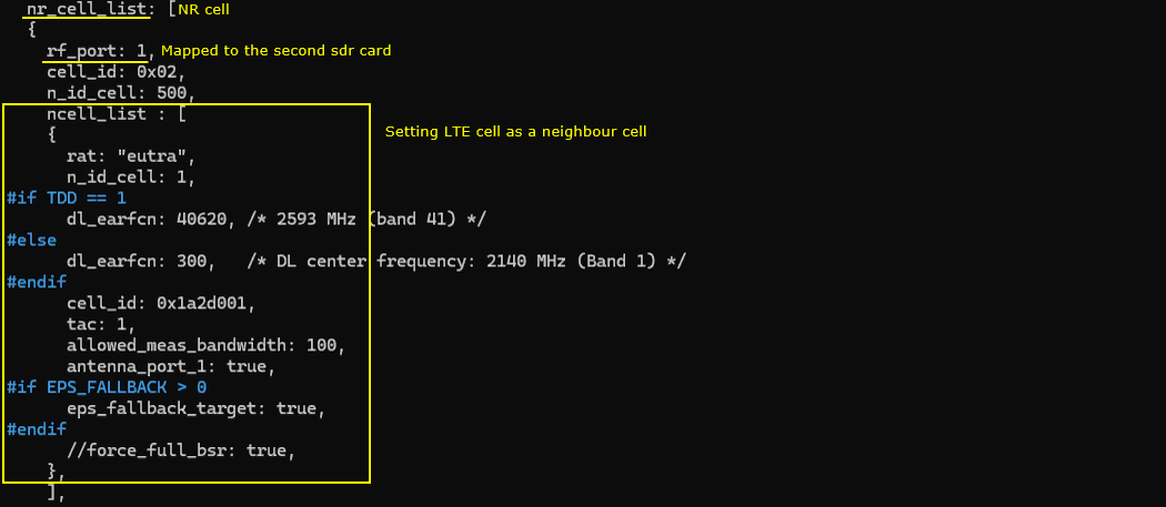
In gnb-sa-lte-ho-n78-b1.cfg , the configuration is done as follows. Since this is based on gnb-sa-lte-ho.cfg the two cell (LTE and NR) are configured by default(N_CELL = 2). In this test, NR is configured as TDD (NR_TDD = 1) and LTE is configured to FDD (TDD = 0)

This is the configuration of the first cell(LTE cell in this test). It is important to note that you need to specify the second cell (n_id_cell : 2) into ncell_list(Neighbour cell list) configuration.

Now specify measurement condition for LTE to NR handover. In this configuration, the measurement is configured to trigger based on event B1. (

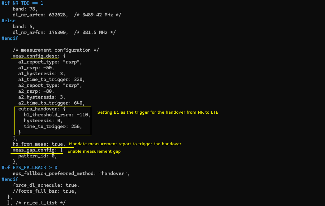
This is the second cell (NR cell) configuration. In this configuration, It is important to note that you need to specify the first cell (n_id_cell : 1) into ncell_list(Neighbour cell list) configuration.
Now specify measurement condition for NR to LTE handover. In this configuration, the measurement is configured to trigger based on event B1
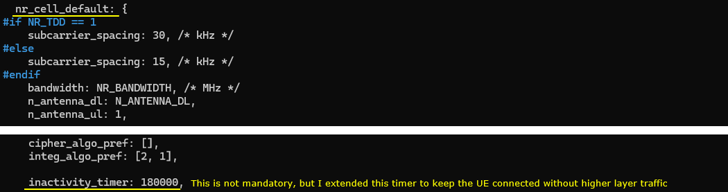
In cell_default configuration, I set a larger value to inactivity_timer. This is to keep the call in connected mode without user data (e.g, ping) and give enough time for you to change tweak cell power to trigger handover. If you keep this value as default (10000), the call will be released and go to idle mode in 10 seconds if you don't flow any user data (e.g, ping).

In the same logic, I set a larger value for inactivity_timer for NR cell as well.
In mme-ims-irat.cfg, the configuration is done as follows.

In ue-ho-irat-LN.cfg, the configuration is done as follows. Since this is a scenario that requires 2 cells, you need to set N_CELL to 2.

This is the cell configuration of the first cell. It does not require any specific configuration. You only neet to set dl_earfcn and bandwidth to match the configuration of the first cell on Callbox.


This is the configuration of the first ue First, you neet to set dl_earfcn and bandwidth to match the configuration of the second cell on Callbox. One important thing to note is that I set cell_index : 1 (the cell index to which NR cell is mapped) in order to force UE to camp on to NR cell. Without this setting, UEsim may always camp onto LTE cell even if LTE cell power is much lower than NR cell. And I set n1_support and s1_support to true to support interRAT handover between NR and LTE.

Perform the Test
Check if the cell is configured as intended. You can check these out with 'cell phy' and 'cell' command.

This is not mandatory, but I would recommend to log SIB messages for a short time and stop so that you can confirm all the sibs for each cells. But I would not recommend you to capture the SIB log all the time since it may make it difficult to analyze other RRC / NAS messages. So I would just collect SIB log just a few seconds at the beginning and stop logging. You can do it with 'log bcch' command.
![]()
On UEsim, check out the result of 'cells' command. If you see the PCI values, it means the cell is detected (PSS/SSS detected).

Power on UE on UE sim.

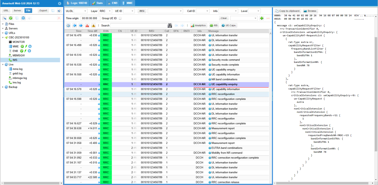
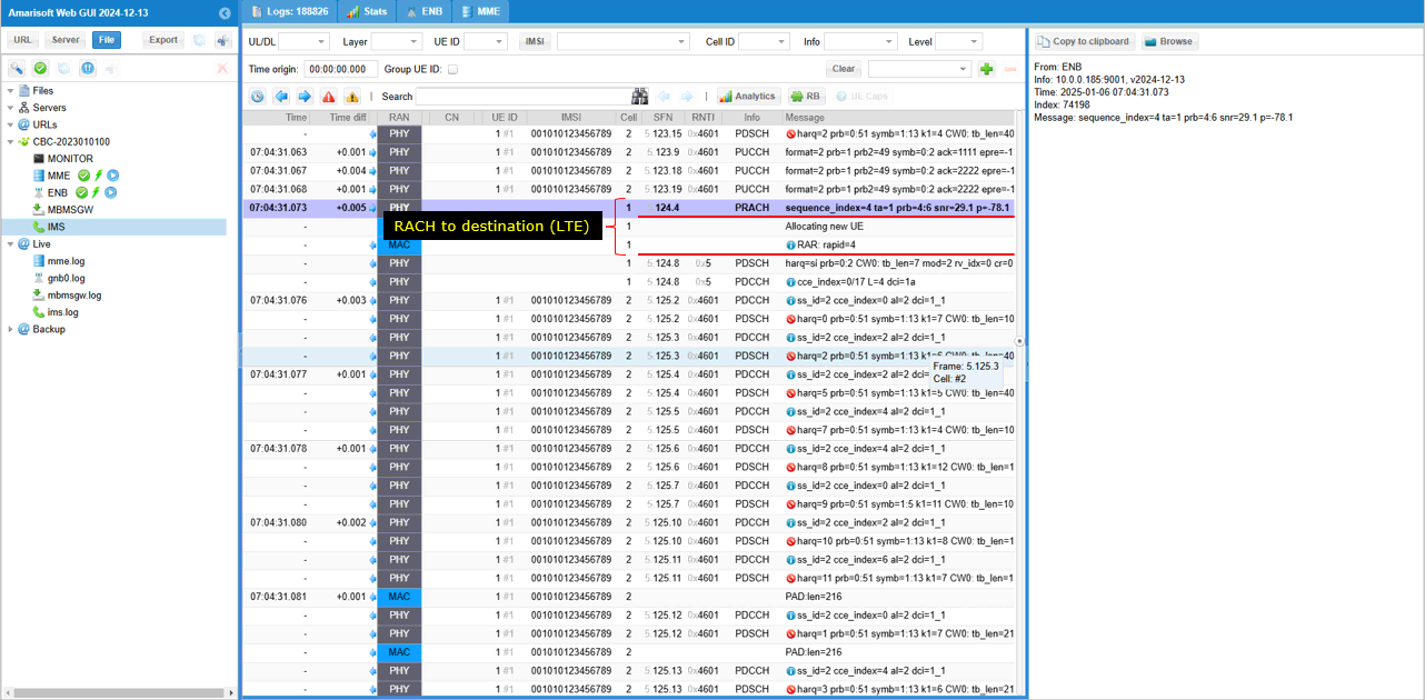
Check the initial attach and tweak the cell power to trigger measurement report and handover. Here you see the two RACH. The first RACH is to cell=02 and the second RACH is to cell=01, which implies that handover might have been triggered and cell switched to target cell.

Log Analysis - Callbox
In this tutorial, this would not be critical but it would always be a good practice to check UeCapability Enquiry and UeCapability Information for every test .

Since this test is for Handover based on measurement report, check if gNB transmits RRC Reconfiguration with measurement configuration and see if the contents of the messages are all set as intended.
First check measObjectToAddModList and see the frequency of both the source and target cells are configured.

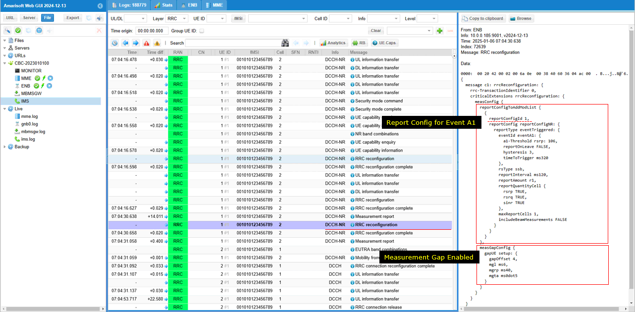
Then check reportConfigToAddModList and see if all the events are configured as intented. Here you see that event a2 and b1 is configured.

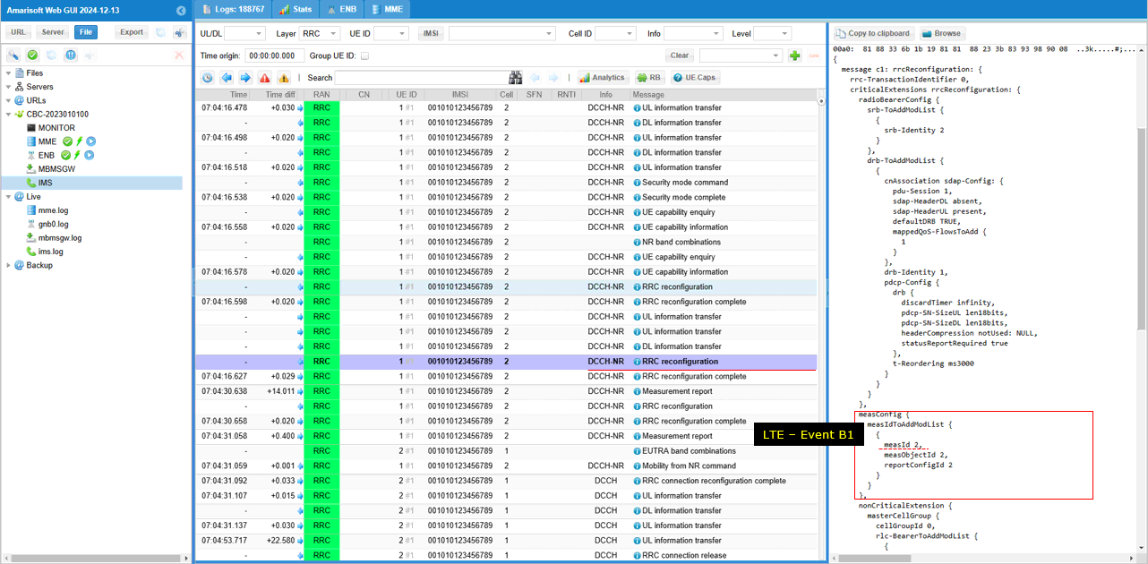
Now check out measIDToAddModList and see if the measurement conditions are configured as intended. Here you see a2 measurement(reportConfigId 1) for NR cell(measObjectId 1) is registered as measId 1. Measurement GAP is not enabled at this point yet.

Here Event B1(reportConfigId 2) for LTE cell(measObjectId 2) is configured and notified to UE.
UE send measurementReport with the reception of A2 event (measId 1)

Now gNB enables measurement Gap (measGapConfig)
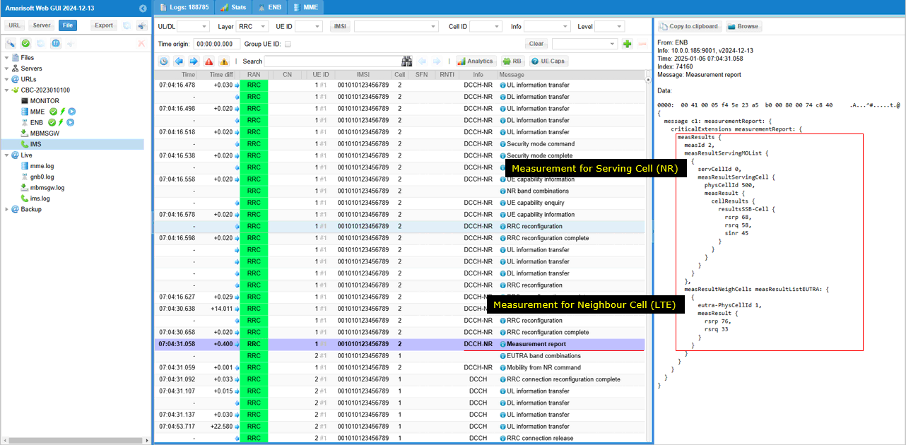
Now UE sends Measurement Report for Event B1 (measId2).
On reception of the Event B1 measurement report, gNB sends 'Mobility from NR command' message to trigger Handover from NR to LTE.
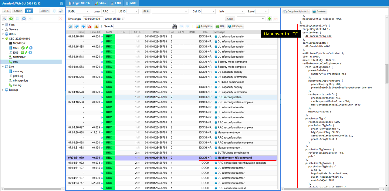
UE performs RACH to the destination cell (LTE cell in this case) and completes Handover.
You can confirm on the result of handover (cell switch) happening in PHY layer by looking into RB map.

Log Analysis - UEsim
In terms of protocol sequence, UE side log (UEsim log) should be exactly same as in gNB log. so what I want to show here is not the signaling log. What I want to show is the internal measurement results being done in UEsim.
One of the most common problems when testing measurement based Handover is that UE does not send the expected measurement report that gNB is expecting. In this case, there is almost nothing to figure out the root cause of the problem just by looking at gNB log. To figure it out, you need to get access to the internal measurement log in your DUT.
The way that these internal log is presented would vary depending on UE modem vendor, but you need to get those log being captured on UEside whatever format it is.
In Amarisoft UEsim, the internal measurement is logged as shown here. For handover, you need to follow up the connected cell measurement refresh log.
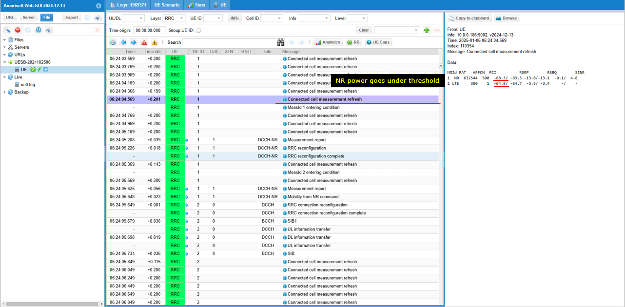
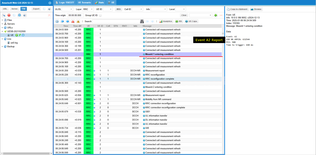
When cell power changes and the power meets any even criteria, UEsim log indicates the detection of the event as shown here (Event A2 in this case). After this internal event detection, you will see the UE transmit RRC measurement Report correspoding to the detected event.
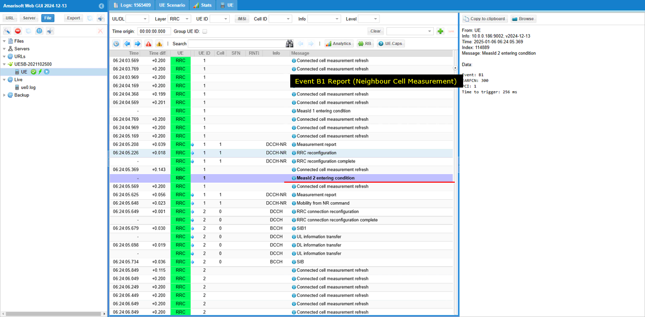
This is another example of event detection on UE side (Event B1 in this case). After this internal event detection, you will see the UE transmit RRC measurement Report correspoding to the detected event.
RRC / NAS Signaling
Here I will just list required message from callbox and I haven't put the required messages from UE side. For the messages from UE, refer to the log analysis and check further with the sample log linked above.
This is the RrcReconfiguration sent by gNB to configure measurement and handover. (
RrcConnectionReconfiguration - Measurement Configuration (1st)
{
message c1: rrcReconfiguration: {
rrc-TransactionIdentifier 0,
criticalExtensions rrcReconfiguration: {
radioBearerConfig {
srb-ToAddModList {
{
srb-Identity 2
}
},
drb-ToAddModList {
{
cnAssociation sdap-Config: {
pdu-Session 1,
sdap-HeaderDL absent,
sdap-HeaderUL present,
defaultDRB TRUE,
mappedQoS-FlowsToAdd {
1
}
},
drb-Identity 1,
pdcp-Config {
drb {
discardTimer infinity,
pdcp-SN-SizeUL len18bits,
pdcp-SN-SizeDL len18bits,
headerCompression notUsed: NULL,
statusReportRequired true
},
t-Reordering ms3000
}
}
}
},
measConfig {
measIdToAddModList {
{
measId 2,
measObjectId 2,
reportConfigId 2
}
}
},
nonCriticalExtension {
masterCellGroup {
cellGroupId 0,
rlc-BearerToAddModList {
{
logicalChannelIdentity 4,
servedRadioBearer drb-Identity: 1,
rlc-Config am: {
ul-AM-RLC {
sn-FieldLength size18,
t-PollRetransmit ms80,
pollPDU p64,
pollByte kB125,
maxRetxThreshold t4
},
dl-AM-RLC {
sn-FieldLength size18,
t-Reassembly ms80,
t-StatusProhibit ms10
}
},
mac-LogicalChannelConfig {
ul-SpecificParameters {
priority 13,
prioritisedBitRate kBps8,
bucketSizeDuration ms100,
logicalChannelGroup 7,
schedulingRequestID 0,
logicalChannelSR-Mask FALSE,
logicalChannelSR-DelayTimerApplied FALSE
}
}
},
{
logicalChannelIdentity 2,
servedRadioBearer srb-Identity: 2,
mac-LogicalChannelConfig {
ul-SpecificParameters {
priority 3,
prioritisedBitRate infinity,
bucketSizeDuration ms5,
logicalChannelGroup 0,
schedulingRequestID 0,
logicalChannelSR-Mask FALSE,
logicalChannelSR-DelayTimerApplied FALSE
}
}
}
}
},
dedicatedNAS-MessageList {
'7E024CF8AD45047E006801007'H
}
}
}
}
}
RrcConnectionReconfiguration - Measurement Configuration (2nd)
{
message c1: rrcReconfiguration: {
rrc-TransactionIdentifier 0,
criticalExtensions rrcReconfiguration: {
measConfig {
reportConfigToAddModList {
{
reportConfigId 1,
reportConfig reportConfigNR: {
reportType eventTriggered: {
eventId eventA1: {
a1-Threshold rsrp: 106,
reportOnLeave FALSE,
hysteresis 3,
timeToTrigger ms320
},
rsType ssb,
reportInterval ms120,
reportAmount r1,
reportQuantityCell {
rsrp TRUE,
rsrq TRUE,
sinr TRUE
},
maxReportCells 1,
includeBeamMeasurements FALSE
}
}
}
},
measGapConfig {
gapUE setup: {
gapOffset 4,
mgl ms6,
mgrp ms40,
mgta ms0dot5
}
}
}
}
}
}
Mobility From NR Command - Handover
{
message c1: mobilityFromNRCommand: {
rrc-TransactionIdentifier 0,
criticalExtensions mobilityFromNRCommand: {
targetRAT-Type eutra,
targetRAT-MessageContainer {
message c1: rrcConnectionReconfiguration: {
rrc-TransactionIdentifier 0,
criticalExtensions c1: rrcConnectionReconfiguration-r8: {
measConfig {
measObjectToAddModList {
{
measObjectId 1,
measObject measObjectEUTRA: {
carrierFreq 300,
allowedMeasBandwidth mbw100,
presenceAntennaPort1 TRUE,
neighCellConfig '01'B
}
},
{
measObjectId 2,
measObject measObjectNR-r15: {
carrierFreq-r15 632544,
rs-ConfigSSB-r15 {
measTimingConfig-r15 {
periodicityAndOffset-r15 sf20-r15: 0,
ssb-Duration-r15 sf1
},
subcarrierSpacingSSB-r15 kHz30
},
quantityConfigSet-r15 1,
bandNR-r15 setup: 78
}
}
},
reportConfigToAddModList {
{
reportConfigId 1,
reportConfig reportConfigEUTRA: {
triggerType event: {
eventId eventA2: {
a2-Threshold threshold-RSRP: 60
},
hysteresis 0,
timeToTrigger ms640
},
triggerQuantity rsrp,
reportQuantity both,
maxReportCells 1,
reportInterval ms120,
reportAmount r1
}
},
{
reportConfigId 2,
reportConfig reportConfigInterRAT: {
triggerType event: {
eventId eventB1-NR-r15: {
b1-ThresholdNR-r15 nr-RSRP-r15: 46,
reportOnLeave-r15 FALSE
},
hysteresis 0,
timeToTrigger ms100
},
maxReportCells 8,
reportInterval ms120,
reportAmount r1,
reportQuantityCellNR-r15 {
ss-rsrp TRUE,
ss-rsrq TRUE,
ss-sinr TRUE
}
}
}
},
measIdToAddModList {
{
measId 1,
measObjectId 1,
reportConfigId 1
},
{
measId 2,
measObjectId 2,
reportConfigId 2
}
},
quantityConfig {
quantityConfigEUTRA {
},
quantityConfigNRList-r15 {
{
measQuantityCellNR-r15 {
}
}
}
},
measGapConfig release: NULL
},
mobilityControlInfo {
targetPhysCellId 1,
carrierFreq {
dl-CarrierFreq 300
},
carrierBandwidth {
dl-Bandwidth n100
},
additionalSpectrumEmission 1,
t304 ms1000,
newUE-Identity '4602'H,
radioResourceConfigCommon {
rach-ConfigCommon {
preambleInfo {
numberOfRA-Preambles n52
},
powerRampingParameters {
powerRampingStep dB2,
preambleInitialReceivedTargetPower dBm-104
},
ra-SupervisionInfo {
preambleTransMax n10,
ra-ResponseWindowSize sf10,
mac-ContentionResolutionTimer sf40
},
maxHARQ-Msg3Tx 5
},
prach-Config {
rootSequenceIndex 120,
prach-ConfigInfo {
prach-ConfigIndex 4,
highSpeedFlag FALSE,
zeroCorrelationZoneConfig 11,
prach-FreqOffset 4
}
},
pdsch-ConfigCommon {
referenceSignalPower -60,
p-b 1
},
pusch-ConfigCommon {
pusch-ConfigBasic {
n-SB 1,
hoppingMode interSubFrame,
pusch-HoppingOffset 8,
enable64QAM TRUE
},
ul-ReferenceSignalsPUSCH {
groupHoppingEnabled FALSE,
groupAssignmentPUSCH 0,
sequenceHoppingEnabled FALSE,
cyclicShift 0
}
},
phich-Config {
phich-Duration normal,
phich-Resource one
},
pucch-ConfigCommon {
deltaPUCCH-Shift ds2,
nRB-CQI 1,
nCS-AN 0,
n1PUCCH-AN 11
},
soundingRS-UL-ConfigCommon setup: {
srs-BandwidthConfig bw2,
srs-SubframeConfig sc3,
ackNackSRS-SimultaneousTransmission TRUE
},
uplinkPowerControlCommon {
p0-NominalPUSCH -85,
alpha al1,
p0-NominalPUCCH -96,
deltaFList-PUCCH {
deltaF-PUCCH-Format1 deltaF0,
deltaF-PUCCH-Format1b deltaF3,
deltaF-PUCCH-Format2 deltaF1,
deltaF-PUCCH-Format2a deltaF2,
deltaF-PUCCH-Format2b deltaF2
},
deltaPreambleMsg3 4
},
antennaInfoCommon {
antennaPortsCount an2
},
p-Max 10,
ul-CyclicPrefixLength len1,
uplinkPowerControlCommon-v1020 {
deltaF-PUCCH-Format3-r10 deltaF-1,
deltaF-PUCCH-Format1bCS-r10 deltaF1
},
pusch-ConfigCommon-v1270 {
enable64QAM-v1270 true
},
pdsch-ConfigCommon-v1310 {
},
pucch-ConfigCommon-v1310 {
},
pusch-ConfigCommon-v1310 {
},
uplinkPowerControlCommon-v1530 {
deltaFList-SPUCCH-r15 release: NULL
}
}
},
radioResourceConfigDedicated {
srb-ToAddModList {
{
srb-Identity 1,
rlc-Config explicitValue: am: {
ul-AM-RLC {
t-PollRetransmit ms60,
pollPDU pInfinity,
pollByte kBinfinity,
maxRetxThreshold t32
},
dl-AM-RLC {
t-Reordering ms45,
t-StatusProhibit ms0
}
},
logicalChannelConfig defaultValue: NULL
},
{
srb-Identity 2,
rlc-Config explicitValue: am: {
ul-AM-RLC {
t-PollRetransmit ms60,
pollPDU pInfinity,
pollByte kBinfinity,
maxRetxThreshold t32
},
dl-AM-RLC {
t-Reordering ms45,
t-StatusProhibit ms0
}
},
logicalChannelConfig defaultValue: NULL
}
},
mac-MainConfig explicitValue: {
ul-SCH-Config {
maxHARQ-Tx n5,
periodicBSR-Timer sf20,
retxBSR-Timer sf320,
ttiBundling FALSE
},
drx-Config release: NULL,
timeAlignmentTimerDedicated infinity,
phr-Config setup: {
periodicPHR-Timer sf500,
prohibitPHR-Timer sf200,
dl-PathlossChange dB3
},
skipUplinkTx-r14 release: NULL,
dataInactivityTimerConfig-r14 release: NULL
},
physicalConfigDedicated {
pdsch-ConfigDedicated {
p-a dB-3
},
pusch-ConfigDedicated {
betaOffset-ACK-Index 9,
betaOffset-RI-Index 6,
betaOffset-CQI-Index 6
},
uplinkPowerControlDedicated {
p0-UE-PUSCH 0,
deltaMCS-Enabled en0,
accumulationEnabled TRUE,
p0-UE-PUCCH 0,
pSRS-Offset 3
},
soundingRS-UL-ConfigDedicated setup: {
srs-Bandwidth bw3,
srs-HoppingBandwidth hbw0,
freqDomainPosition 0,
duration TRUE,
srs-ConfigIndex 37,
transmissionComb 0,
cyclicShift cs1
},
schedulingRequestConfig setup: {
sr-PUCCH-ResourceIndex 0,
sr-ConfigIndex 15,
dsr-TransMax n64
},
antennaInfo-r10 explicitValue-r10: {
transmissionMode-r10 tm3,
codebookSubsetRestriction-r10 '11'B,
ue-TransmitAntennaSelection release: NULL
},
cqi-ReportConfig-r10 {
cqi-ReportAperiodic-r10 release: NULL,
nomPDSCH-RS-EPRE-Offset 0,
cqi-ReportPeriodic-r10 setup: {
cqi-PUCCH-ResourceIndex-r10 0,
cqi-pmi-ConfigIndex 38,
cqi-FormatIndicatorPeriodic-r10 widebandCQI-r10: {
},
ri-ConfigIndex 483,
simultaneousAckNackAndCQI TRUE
}
},
pdsch-ConfigDedicated-v1280 {
},
pdsch-ConfigDedicated-v1430 {
},
pusch-ConfigDedicated-v1430 {
ul-DMRS-IFDMA-r14 FALSE,
enable256QAM-r14 release: NULL
},
pdsch-ConfigDedicated-v1530 {
}
},
drb-ToAddModList-r15 {
{
eps-BearerIdentity 5,
drb-Identity 1,
rlc-Config am: {
ul-AM-RLC {
t-PollRetransmit ms80,
pollPDU p64,
pollByte kB125,
maxRetxThreshold t32
},
dl-AM-RLC {
t-Reordering ms35,
t-StatusProhibit ms10
}
},
logicalChannelIdentity 3,
logicalChannelConfig {
ul-SpecificParameters {
priority 15,
prioritisedBitRate kBps8,
bucketSizeDuration ms100,
logicalChannelGroup 3
}
}
}
}
},
nonCriticalExtension {
nonCriticalExtension {
otherConfig-r9 {
powerPrefIndicationConfig-r11 release: NULL
},
fullConfig-r9 true,
nonCriticalExtension {
nonCriticalExtension {
nonCriticalExtension {
nonCriticalExtension {
nonCriticalExtension {
nonCriticalExtension {
nr-RadioBearerConfig1-r15 {
drb-ToAddModList {
{
cnAssociation eps-BearerIdentity: 5,
drb-Identity 1,
pdcp-Config {
drb {
discardTimer infinity,
pdcp-SN-SizeUL len18bits,
pdcp-SN-SizeDL len18bits,
headerCompression notUsed: NULL,
statusReportRequired true
},
t-Reordering ms3000
}
}
},
securityConfig {
securityAlgorithmConfig {
cipheringAlgorithm nea0
},
keyToUse master
}
},
nonCriticalExtension {
securityConfigHO-v1530 {
handoverType-v1530 fivegc-ToEPC: {
securityAlgorithmConfig-r15 {
cipheringAlgorithm eea0,
integrityProtAlgorithm eia2
},
nextHopChainingCount-r15 2
}
}
}
}
}
}
}
}
}
}
}
}
}
},
nas-SecurityParamFromNR '05'H
}
}
}