TRX API
The purpose of this tutorial is to explain about the architecture and details of TRX API. TRX API is a set of specification defined by Amarisoft which is designed for implementing software libraries connecting various RF hardware (e.g, sdr card, cpri card, USRP etc) to Amarisoft software (e.g, Amarisoft Callbox). We are sharing the specification of TRX API for other users to implement their own software libraries to connect user's hardware to Amarisoft application.
Table of Contents
- TRX API
- Introduction
- Summary of the Tutorial
- Underlying Structure
- Implementation Example in Amarisoft Product
- Interaction between Application SW and TRX API SW
- TRX_Dummy : The Template
- Overall Structure
- Where to get ?
- Code Review
- trx_driver_init
- trx_dummy_start
- trx_dummy_read
- trx_dummy_write
- TRX_uSDR : Working Example with Amarisoft SDR Card
Introduction
TRX API represents a critical architectural interface designed by Amarisoft to bridge the gap between diverse radio frequency (RF) hardware and the suite of Amarisoft software solutions, such as the Amarisoft Callbox. By standardizing the communication protocols and data exchange formats between the software and a variety of RF front-ends—including SDR cards, CPRI cards, and USRP devices—the TRX API enables seamless integration and interoperability in advanced wireless communication environments. The API abstracts hardware-specific implementation details, offering a unified set of function calls and signaling mechanisms that facilitate low-latency, high-throughput data transfer essential for real-time wireless protocol stacks. Within the broader telecommunications ecosystem, the TRX API empowers users to leverage custom or third-party RF hardware with Amarisoft’s software, thus fostering innovation, flexibility, and rapid prototyping in wireless network research and development. This architecture is pivotal in enabling software-defined radio solutions, supporting evolving standards, and accelerating deployment cycles for experimental and commercial wireless systems.
-
Context of TRX API
- TRX API is a hardware abstraction layer for integrating RF front-ends with Amarisoft's telecom software.
- It supports a variety of hardware interfaces, including SDR, CPRI, and USRP, ensuring broad compatibility.
- The specification defines standard data paths, timing synchronization, and control signaling between hardware and software components.
-
Relevance and Importance
- Enables rapid development and deployment of wireless networks with flexible hardware choices.
- Supports research, prototyping, and commercial deployments by decoupling software from hardware dependencies.
- Promotes community-driven innovation by allowing third parties to develop their own TRX-compliant libraries for new or proprietary RF hardware.
-
Learning Outcomes
- Understand the high-level architecture and design principles behind the TRX API.
- Gain insight into how Amarisoft software interfaces with RF hardware through standardized APIs.
- Acquire the foundational knowledge required to implement or adapt TRX API libraries for custom hardware.
- Develop awareness of best practices for integrating and validating new RF hardware within Amarisoft’s ecosystem.
-
Prerequisite Knowledge
- Familiarity with wireless communication systems and RF hardware concepts.
- Basic understanding of software APIs, device drivers, and data path architectures.
- Experience with C/C++ programming and software integration is advantageous for implementation work.
- Prior exposure to Amarisoft software stack is helpful but not strictly required.
Summary of the Tutorial
This tutorial provides an overview of the TRX API structure, its implementation in Amarisoft products, interaction mechanisms between the application and TRX API software, and the use of a dummy template (trx_example.c) for TRX driver development. The document also outlines the procedures and methodologies for initializing and connecting TRX drivers in a test or development environment.
-
Underlying Structure and Architecture
- The TRX Driver exposes a set of APIs (TRX API) mapped to various TRX operation functions within the Amarisoft Application.
- TRX API controls or communicates with RF hardware either directly or through an additional RF Driver layer.
- In Amarisoft SDR implementations, the TRX driver (e.g., trx_sdr.so) interfaces with user-level (libsdr.so) and kernel-level (sdr.ko) drivers to achieve hardware abstraction and control.
-
Interaction between Application Software and TRX API
- Three main interaction mechanisms are described:
- Type 1: Function Invocation
- Application software invokes TRX API functions (e.g., trx_xxxx_func()).
- Acts as triggers for TRX operations and is handled through callback functions.
- Type 2: Parameter Retrieval
- Application queries the TRX API for various parameters (e.g., trx_get_param_xxxx()).
- Allows retrieval of configuration and operational parameters by the TRX API.
- Type 3: Data & Configuration Exchange
- Parameters are shared between the application and TRX API via a common parameter set.
- Ensures correct RF driver configuration and coherence between software stack and SDR hardware.
- Type 1: Function Invocation
- Three main interaction mechanisms are described:
-
TRX Dummy Template (trx_example.c) for Driver Development
- A template source file (trx_example.c) is provided as a starting point for TRX driver development.
- Users are instructed to:
- Unpack (untar) the template from the installation package (not installed by default).
- Compile it using the provided Makefile.
- Modify function names and add custom code to suit specific RF hardware requirements.
- The template includes essential API functions such as:
- trx_driver_init
- trx_dummy_start
- trx_dummy_read
- trx_dummy_write
- trx_dummy_end
-
Test Procedure: TRX Driver Initialization (trx_driver_init)
- The trx_driver_init function is the first to be called for establishing the connection between the Amarisoft Application and the TRX driver.
- Main steps:
- Checks ABI compatibility between the LTEENB and the TRX driver; logs error and returns -1 on mismatch.
- Allocates and initializes the internal state structure (e.g., TRXDummyState), setting important fields (e.g., dump_max).
- Updates the TRXState structure by mapping operational callbacks (end, write, read, start, get_sample_rate) to corresponding dummy functions.
- Links driver state to user-defined structures for internal use (e.g., s1->opaque = s).
- Returns 0 on successful initialization.
- This procedure sets up the driver with dummy behaviors for all core operations, serving as the foundation for further customization.
Overall, the tutorial guides users through understanding the TRX API structure, adapting the provided template for their own hardware, and correctly initializing the driver to establish communication with the Amarisoft software stack. The focus is on high-level procedures and code structure necessary for custom TRX driver development and testing.
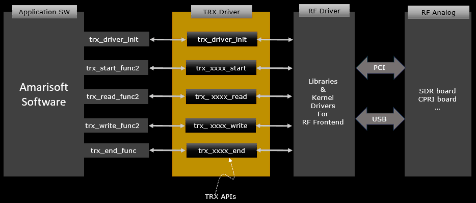
Underlying Structure
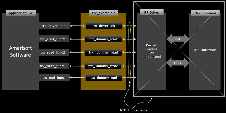
The underlying structure and functionality of TRX API are illustrate as below. As shown here, the component labeled as TRX Driver has a set of APIs (i.e, TRX API) which are mapped to various trx operation functions of Amarisoft Application and controls/communicate with RF hardware indirectly (i.e, via RF Driver(another layer of driver stack) or directly.
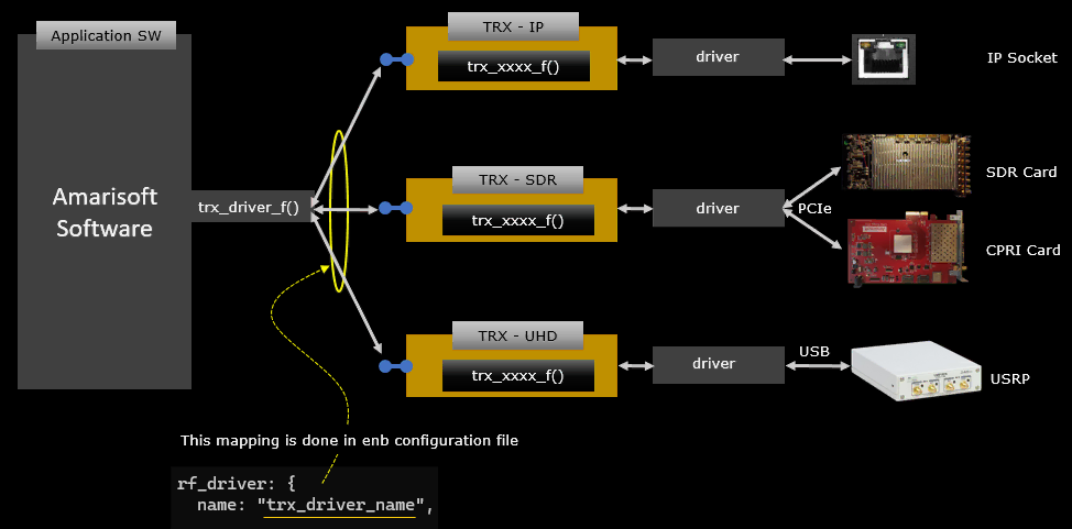
Implementation Example in Amarisoft Product
Following is some of example architectures of TRX driver being used in Amarisoft product. As illustrated here, TRX API has widely and long been used in Amarisoft software stack implying that the architecture has well been verified.
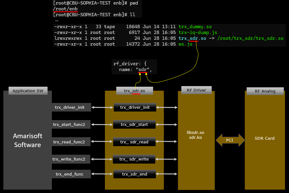
As a concrete example, the architecture of Amarisoft sdr driver is illustrate below. For Amarisoft SDR card, the TRX driver named trx_sdr.so is implemented according to TRX API specification. In case of Amarisoft sdr, trx_sdr (TRX Driver) is mapped to Amarisoft Callbox or UEsim software and communicating with RF driver (libsdr.so and sdr.ko) which communicate/control the physical SDR card.
Interaction between Application SW and TRX API SW
In order for Application SW (e.g, Amarisoft eNB/gNB) and TRX API SW (e.g, libsdr) work together seamlessly, there should be sophisticated mechanism for interaction between them. There are roughly three types of interaction mechanism as shown below.
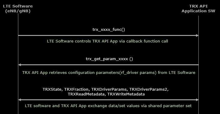
Followings are brief descriptions of each of these mechanism
- Type 1: Function Invocation
- LTE Software calls TRX API functions (e.g., trx_xxxx_func()).
- Acts as a trigger for TRX API operations.
- Controlled through callback function calls.
- Type 2: Parameter Retrieval
- LTE Software queries TRX API for parameters using calls like trx_get_param_xxxx().
- TRX API App retrieves configuration parameters from LTE Software.
- Type 3: Data & Configuration Exchange
- LTE Software and TRX API App share parameters through a shared parameter set.
- This exchange ensures:
- Correct RF driver configuration (rf_driver params).
- Consistency between LTE stack and SDR hardware control.
- Values can be both set and retrieved .
TRX_Dummy : The Template
As a starter of the TRX driver implementation, we provide a simple template of TRX driver named trx_example.c. You may use this template as a starting point, change the name of the function and adding your own code for controlling/connecting to RF hardware.
Overall Structure
Overall structure of trx_example.c is as shown below. It has several core APIs as specified in TRX API specification, named trx_driver_init, trx_dummy_start, trx_dummy_read, trx_dummy_write, trx_dummy_end respectively. Each of these functions are mapped to trx functions in Amarisoft Application as specified in the specification. One major difference between this template and real implementation is that the API implemented this function does not have any real connection to lower layer drivers which are connected to any hardware.
Where to get ?
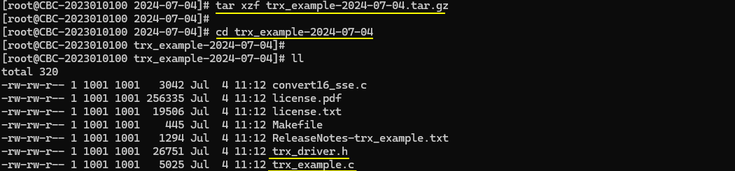
The TRX API template is included in installation package but does not get installed on the system during the installation procedure. You need to unpack (untar) this component manually from the installation package.
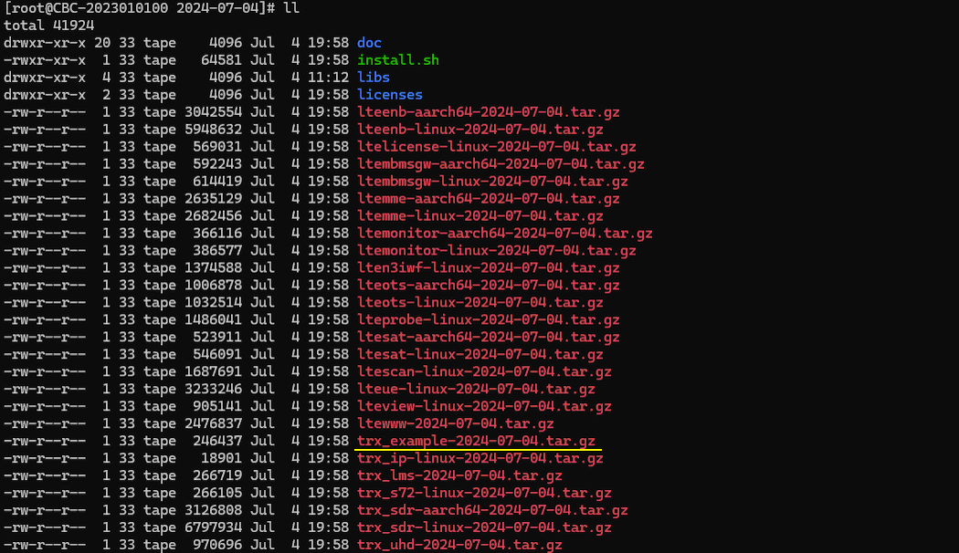
Once you unpack (untar) the trx_example component, you will get the trx_example.c source code, trx_driver header file and Makefile to compile it.
Code Review
Now let's look into the source file and see what it mean. What you can do with this part is to try to understand overall code structure and figure out where to put your own routine to control/communicate with your own RF hardware.
trx_driver_init
As you see in the diagram of TRX API lifetime , trx_driver_init would be the first function being called to establish connection between Amarisoft Application software and TRX driver. As the name indicate, it performs various steps for initialization of TRX driver and make mapping between TRX API interface functions (e.g, trx_read_func2, trx_write_func2 etc) and user defined functions(e.g, trx_dummy_read, trx_dummy_write etc). Usually this functions does various parameter initialization but would not perform any of RF hardware configuration.
|
int trx_driver_init(TRXState *s1) { TRXDummyState *s; double val;
if (s1->trx_api_version != TRX_API_VERSION) { fprintf(stderr, "ABI compatibility mismatch between LTEENB and TRX driver (LTEENB ABI version=%d, TRX driver ABI version=%d)\n", s1->trx_api_version, TRX_API_VERSION); return -1; }
s = malloc(sizeof(TRXDummyState)); memset(s, 0, sizeof(*s)); s->dump_max = 0;
/* option to dump the maximum sample value */ if (trx_get_param_double(s1, &val, "dump_max") >= 0) s->dump_max = (val != 0);
s1->opaque = s; s1->trx_end_func = trx_dummy_end; s1->trx_write_func2 = trx_dummy_write; s1->trx_read_func2 = trx_dummy_read; s1->trx_start_func2 = trx_dummy_start; s1->trx_get_sample_rate_func = trx_dummy_get_sample_rate; return 0; } |
trx_dummy_start
As you see in the diagram of TRX API lifetime , this function corresponds to 'Start' step of the diagram. This is the good place where you start RF hardware and initialize the time stamp. You may add your own routine for starting your RF hardware (e.g, function call for your hardware specific API) in this function.
|
/* * This function initializes the dummy start process for a TRX session. * It first retrieves the internal state from the opaque pointer in the TRXState structure. The function checks if the number of RF ports is exactly one, as only one TX port is supported. * If not, it returns -1 to indicate an error. * It then sets the sample rate by dividing the numerator by the denominator from the provided parameters. The TX and RX channel counts are also set based on the input parameters. * A timestamp is generated using `gettimeofday` to compute the first RX timestamp in sample rate units. This involves converting the current time in seconds to sample rate units and adding the * microseconds part, also converted to sample rate units.Finally, it records the last disp time using `get_time_us()` and returns 0 to indicate success. */ static int trx_dummy_start(TRXState *s1, const TRXDriverParams2 *p) { TRXDummyState *s = s1->opaque; struct timeval tv;
if (p->rf_port_count != 1) return -1; /* only one TX port is supported */
s->sample_rate = p->sample_rate[0].num / p->sample_rate[0].den; s->tx_channel_count = p->tx_channel_count; s->rx_channel_count = p->rx_channel_count;
gettimeofday(&tv, NULL); /* compute first RX timetamp in sample rate units */ s->rx_timestamp = (int64_t)tv.tv_sec * s->sample_rate + ((int64_t)tv.tv_usec * s->sample_rate / 1000000);
s->last_disp_time = get_time_us(); return 0; } |
trx_dummy_read
trx_dummy_read is the function where you put the routine to read(recieve) IQ data from RF hardware. You have to implement a routine in this function that waits until IQ data from hardware is available and read a chunk of data when available. And then put the time stamp to the read chunk. (
|
/* * This function simulates reading samples for a TRX session. * It updates the timestamp for received samples and increments the received sample count. The function then calculates the end time for the current batch of samples based on the updated timestamp. * A loop is used to simulate the delay until the end time, using the PC's real-time clock. If the calculated delay is more than 10 milliseconds, it's capped at 10 milliseconds to avoid long sleeps. * Finally, for each RX channel, it fills the provided sample buffer with zeros to simulate receiving blank samples. * The function returns the count of samples supposedly read, which matches the requested count. * * Parameters: * - s1: Pointer to the TRXState structure, which includes the opaque pointer to the TRXDummyState. * - timestamp: The timestamp for the samples being read. * - samples: An array of pointers to the sample buffers for each TX channel. * - count: The number of samples per channel. * - rf_port_index: The index of the RF port being written to. * - md: Metadata associated with the write operation, including flags. */ static int trx_dummy_read(TRXState *s1, trx_timestamp_t *ptimestamp, void **psamples, int count, int rf_port_index, TRXReadMetadata *md) { TRXDummyState *s = s1->opaque; int64_t end_time, d; TRXComplex *samples; int j;
*ptimestamp = s->rx_timestamp; s->rx_timestamp += count; s->rx_count += count; end_time = ts_to_time(s, s->rx_timestamp); /* Since we don't have a real sample source, we just return zero samples and use the PC real time clock as time source */ for(;;) { d = end_time - get_time_us(); if (d <= 0) break; if (d > 10000) d = 10000; usleep(d); }
for(j = 0; j < s->rx_channel_count; j++) { samples = psamples[j]; memset(samples, 0, count * sizeof(TRXComplex)); } return count; } |
trx_dummy_write
trx_dummy_write is the function where you put the routine to write(transmit) IQ data to RF hardware. You have to implement a routine in this function that send a chunk of IQ data to RF hardware. (
|
/* * This function handles the writing of samples in the dummy TRX implementation. It processes the samples provided to it, updating the maximum sample value and saturation count. * * Parameters: * - s1: Pointer to the TRXState structure, which includes the opaque pointer to the TRXDummyState. * - timestamp: The timestamp for the samples being written. * - samples: An array of pointers to the sample buffers for each TX channel. * - count: The number of samples per channel. * - rf_port_index: The index of the RF port being written to. * - md: Metadata associated with the write operation, including flags. * * The function first checks if the write operation is not just padding and if the dump_max flag is set. * It then iterates over each TX channel and each sample within the channel: * - Computes the absolute value of each sample. * - Updates the saturation count if the sample value is at or above the maximum representable value (1.0). * - Tracks the maximum sample value encountered. * * If more than 2 seconds have passed since the last display, it prints the maximum sample value and saturation count, then resets these metrics and updates the last display time. * Finally, it increments the total count of transmitted samples. */
static void trx_dummy_write(TRXState *s1, trx_timestamp_t timestamp, const void **samples, int count, int rf_port_index, TRXWriteMetadata *md) { TRXDummyState *s = s1->opaque;
if (!(md->flags & TRX_WRITE_FLAG_PADDING) && s->dump_max) { const float *tab; int i, j; float v_max, v;
v_max = s->max_sample; for(j = 0; j < s->tx_channel_count; j++) { tab = (const float *)samples[j]; for(i = 0; i < count * 2; i++) { v = fabsf(tab[i]); /* Note: 1.0 corresponds to the maximum value */ if (v >= 1.0) s->sat_count++; if (v > v_max) { v_max = v; } } } s->max_sample = v_max; if ((get_time_us() - s->last_disp_time) >= 2000000) { printf("max_sample=%0.3f sat=%d\n", s->max_sample, s->sat_count); s->max_sample = 0; s->sat_count = 0; s->last_disp_time = get_time_us(); } }
s->tx_count += count; } |
TRX_uSDR : Working Example with Amarisoft SDR Card
In this sample, I will show a working example of how to write a TRX API driver at the user level for an Amarisoft SDR card. The goal is not to build a full-featured production driver. The goal is to provide a simple but working baseline that helps you understand the overall structure and flow of a TRX driver in a practical way.
This example is intentionally kept to the bare minimum. It focuses only on the essential parts needed to make the driver work with the Amarisoft SDR card. This makes it easier to study the code, trace the behavior, and experiment with the implementation without being distracted by unnecessary complexity. With this approach, you can practice writing and testing a TRX driver even if you do not have any third-party SDR hardware. It is a convenient starting point for getting familiar with the driver model, the callback structure, the initialization flow, and the interaction between Amarisoft software and the SDR device.
Another important purpose of this example is to help you understand the concept of a user-level TRX driver. Once you see a minimal working implementation, it becomes much easier to understand which parts are generic and which parts are hardware-specific. This distinction is very important when you later want to support your own SDR platform.
If you want to use your own hardware instead of the Amarisoft SDR card, you can use this example as a template. The overall driver framework can remain mostly the same. What you would mainly need to change is the hardware-dependent portion, especially the Amarisoft-specific function calls such as `msdrv_xxxx`. Those parts should be replaced with the corresponding APIs, SDK calls, or control functions provided by your own hardware vendor. In this sense, this sample can serve as a bridge between understanding the Amarisoft TRX API model and building a custom driver for a completely different SDR platform.
Overall, this example is meant to be a hands-on starting point. It gives you a working reference, helps you learn the essential concepts quickly, and provides a practical foundation that you can later extend for your own SDR hardware and more advanced driver features.
Overall Structure
The overall structure of trx_usdr.c in this example follows the standard TRX driver model defined by the Amarisoft TRX API. The main idea is that the Amarisoft application does not directly control the SDR hardware by itself. Instead, it calls a set of callback functions that are provided by the driver shared library, in this case trx_usdr.so. These callback functions form the interface layer between the Amarisoft software stack and the actual RF driver or hardware access layer.
As shown in the diagram, the software stack on the left contains the TRX function pointers expected by Amarisoft. During initialization, these function pointers are connected to the actual driver functions implemented inside trx_usdr.c. This connection is typically done inside trx_driver_init(). In other words, trx_driver_init() is the entry point that tells Amarisoft, �when you need this TRX operation, call this specific function in my driver�.
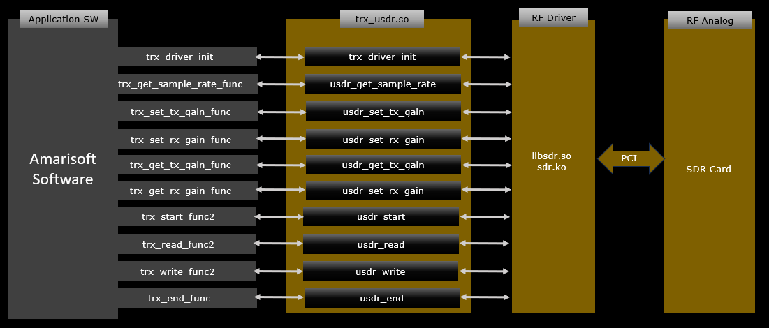
The overall structure of trx_usdr.c therefore consists of a small set of core APIs that match the TRX API specification. In this example, those core functions are things like trx_driver_init, usdr_start, usdr_read, usdr_write, and usdr_end. In your earlier dummy-style explanation, these may appear as trx_dummy_start, trx_dummy_read, trx_dummy_write, and trx_dummy_end, but in the actual trx_usdr.c they are implemented with usdr_xxx naming to indicate that they are the real driver-side functions for the USDR-based backend.
The most important function is trx_driver_init(). This function does not usually perform continuous TX or RX processing by itself. Its main role is to build the mapping between the Amarisoft callback table and the actual driver implementation. It registers which function should be used for each required operation. For example, when Amarisoft wants to get the sample rate, it does not call the RF library directly. It calls the function pointer trx_get_sample_rate_func, and this is mapped by trx_driver_init() to the actual driver-side function usdr_get_sample_rate. The same pattern applies to TX gain control, RX gain control, start, read, write, and end processing.
So the flow is like this. Amarisoft defines a set of stub or hook points such as trx_set_tx_gain_func, trx_read_func2, and trx_end_func. The driver code in trx_usdr.c implements the real functions such as usdr_set_tx_gain, usdr_read, and usdr_end. Then trx_driver_init() connects the two sides together. Once this mapping is completed, Amarisoft can use the driver as if it were calling its own internal functions, while in reality the execution is handed over to the external shared object trx_usdr.so.
Each mapped function has a clear role in the driver lifecycle. trx_driver_init() performs registration and basic setup. usdr_get_sample_rate reports the supported or configured sample rate to the upper stack. usdr_set_tx_gain and usdr_set_rx_gain handle transmit and receive gain control. usdr_get_tx_gain and usdr_get_rx_gain return the currently configured gain values. usdr_start initializes streaming and prepares the SDR path for operation. usdr_read is used when Amarisoft wants to fetch received I/Q samples from the SDR side. usdr_write is used when Amarisoft wants to send transmit I/Q samples down to the SDR side. usdr_end performs shutdown and cleanup when the TRX path is stopped.
This structure is important because it cleanly separates responsibilities into multiple layers. Amarisoft application software only knows the generic TRX API. The shared library trx_usdr.so implements that API in the form of callback functions. Under that, the driver talks to the lower RF driver layer such as libsdr.so or sdr.ko. Finally, the kernel driver and RF analog hardware communicate with the actual SDR card through PCI. Because of this layered structure, Amarisoft does not need to know any hardware-specific details. All hardware dependency is isolated inside the driver implementation.
This is why trx_driver_init() is the key structural point in the whole file. It acts as the binding stage between the upper Amarisoft software stack and the lower hardware-dependent implementation. Once you understand this mapping model, it becomes easier to write your own TRX driver. If you later want to support another SDR platform, you can keep the same Amarisoft-facing TRX callback structure and only replace the hardware-specific body of functions such as usdr_start, usdr_read, usdr_write, and the low-level access routines that interact with the RF driver or vendor SDK.
In summary, the overall structure of trx_usdr.c is centered around a callback registration model. The file implements the required TRX APIs, and trx_driver_init() maps Amarisoft�s expected stub functions to the actual driver functions inside the shared library. After this mapping is complete, Amarisoft uses these registered callbacks for all major radio operations such as configuration, streaming, gain control, sample transfer, and shutdown. This makes trx_usdr.c a practical example of how a TRX driver is organized and how the upper software stack is connected to the lower hardware-specific implementation.
Code Structure
This diagram below shows the full execution structure of the example TRX driver from the application side down to the hardware-facing side. It explains not only which functions exist, but also when each function is called and what role each one plays in the lifetime of the driver.
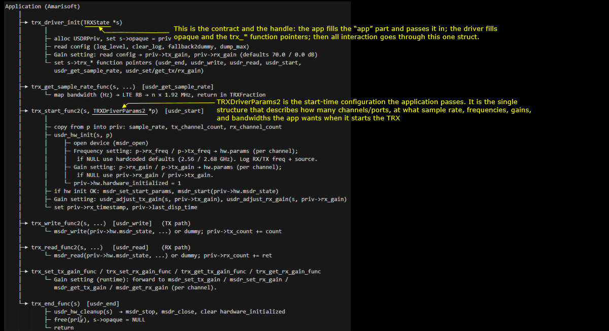
At the top level, the Amarisoft application does not directly access the SDR hardware. Instead, it talks only to a single driver interface through the TRXState *s structure. This structure is the main contract between the application and the driver. The application prepares the application-related part of this structure and passes it into trx_driver_init(). Then the driver fills in its own private context and registers the callback functions such as start, read, write, gain control, and stop. After this point, almost all interaction between Amarisoft and the driver goes through this one handle.
The first step is trx_driver_init(TRXState *s). This is the real entry point of the driver. In this function, the driver allocates its private context, often something like USDRPriv, and stores it into s->opaque. This private structure holds all driver-specific state such as configured gains, sample rate, channel count, hardware flags, counters, timestamps, and device handles. The driver also reads initial configuration values from the Amarisoft side, such as log level, default duplex mode, and startup gain values. Most importantly, this function connects the Amarisoft TRX callback slots to the actual functions implemented in the driver. For example, it binds the application's trx_start_func2 entry to usdr_start, trx_write_func2 to usdr_write, trx_read_func2 to usdr_read, and the gain-related hooks to the corresponding gain control functions. This is the point where the generic Amarisoft interface becomes linked to the hardware-specific implementation.
After initialization, Amarisoft may call trx_get_sample_rate_func(s, ...), which is mapped to usdr_get_sample_rate. This function is used to convert a logical LTE or NR bandwidth request into the exact sampling rate that the driver and hardware should use. In many practical implementations, the application may request something like a bandwidth in MHz, and the driver returns the appropriate sample rate in TRX fractional format. This function is important because it allows the upper layer to remain generic while the driver decides the actual numeric rate required by the hardware.
The next major stage is trx_start_func2(s, TRXDriverParams2 *p), which is mapped to usdr_start. This is the point where the application actually starts the radio path. The TRXDriverParams2 structure is the startup configuration package passed from Amarisoft to the driver. It describes the requested operating conditions at start time, such as how many TX and RX channels are needed, what sample rate should be used, which TX and RX frequencies should be tuned, and what gain and bandwidth settings are requested. In other words, this structure describes the radio configuration the application wants the driver to realize before sample streaming begins.
Inside usdr_start, the driver typically copies the important values from TRXDriverParams2 into its private context. This includes the sample rate and channel counts. Then it calls a lower-level helper such as usdr_hw_init(s, p) to perform actual hardware preparation. In this hardware initialization stage, the driver opens the device, programs the RF frequencies, sets per-channel parameters, and loads default values if some application parameters are absent. This is where the driver begins talking to the low-level RF layer, such as msdr_open, msdr_set_start_params, or similar hardware-specific functions. If the hardware is successfully initialized, the driver marks itself as ready, adjusts TX and RX gains as needed, and prepares internal timestamp state so that TX and RX data movement can stay synchronized with Amarisoft timing.
Once startup is complete, Amarisoft enters the streaming phase. When the application has transmit samples to send, it calls trx_write_func2(s, ...), which is mapped to usdr_write. This is the TX path. The driver receives the I/Q samples from the upper stack and forwards them to the lower RF driver or hardware API. In a real hardware implementation, this could mean calling a hardware-specific function to push those samples into the transmit DMA or RF pipeline. In a simplified dummy version, it may just count the samples or emulate successful transmission. Either way, this function is the application-to-hardware data path for transmit.
Similarly, when Amarisoft wants received samples, it calls trx_read_func2(s, ...), which is mapped to usdr_read. This is the RX path. The driver fetches I/Q samples from the lower RF side and returns them upward to the application. In a real implementation, this function may pull samples from a hardware ring buffer, DMA queue, or device API. In a minimal example, it may generate dummy data or simply return a placeholder number of samples. Conceptually, this is the hardware-to-application data path for receive.
In parallel with TX and RX streaming, Amarisoft can also call runtime control functions such as trx_set_tx_gain_func, trx_set_rx_gain_func, trx_get_tx_gain_func, and trx_get_rx_gain_func. These are mapped to the corresponding driver functions such as usdr_set_tx_gain, usdr_set_rx_gain, usdr_get_tx_gain, and usdr_get_rx_gain. These functions allow the application to adjust or query gain values while the radio is active. Typically, the driver forwards these requests to hardware-specific APIs on a per-channel basis. This is important because not all radio settings are fixed only at startup. Some parameters may need to be tuned dynamically during runtime.
Finally, when Amarisoft wants to stop using the driver, it calls trx_end_func(s), which is mapped to usdr_end. This is the cleanup and shutdown stage. Here the driver stops the hardware stream, closes the device handle, clears the initialized state, releases all allocated memory, and disconnects the private context from s->opaque. This ensures that the driver exits cleanly and leaves no stale hardware state behind.
So, if we summarize the overall code structure in a lifecycle view, it works like this. trx_driver_init() builds the contract and registers the callbacks. trx_get_sample_rate_func() answers how the requested bandwidth maps to a real sample rate. trx_start_func2() takes the startup configuration and prepares the hardware. trx_write_func2() handles the TX sample path. trx_read_func2() handles the RX sample path. The gain functions manage runtime RF control. trx_end_func() tears everything down.
This is why the diagram is useful. It shows that trx_usdr.c is not just a flat collection of random functions. It is organized as a clear driver lifecycle. Initialization creates the binding. Start applies the operating configuration. Read and write handle continuous streaming. Gain APIs provide runtime control. End performs cleanup. Once you understand this structure, it becomes much easier to replace the Amarisoft-specific or USDR-specific hardware calls with those for your own SDR platform while keeping the same Amarisoft-facing framework unchanged.
Code Details
In this section, we will look directly into the source code itself and see how the TRX driver is actually implemented. So far, we have focused on the overall architecture and the relationship between the Amarisoft application, the callback mapping, and the lower hardware layer. Now the focus shifts from the conceptual view to the implementation details inside the code.
By going through the source code, we can see how each callback function is defined, how the private driver context is created and managed, how the initialization is performed, and how the TX and RX paths are connected to the hardware-facing routines. This will make the earlier block diagrams much clearer, because the code shows exactly where the mapping happens and how the driver lifecycle is realized in practice.
In other words, this section is where the abstract TRX API structure becomes concrete. We will examine how `trx_driver_init()` sets up the driver, how the start/read/write/end functions are implemented, and how each piece of the code corresponds to the operational flow described in the previous diagrams.
trx_driver_init() is the driver entry point that Amarisoft calls first. It creates the driver's private context, initializes default settings, checks whether the TRX API version matches the application's expected version, reads optional configuration parameters from the Amarisoft side, and then registers all the callback functions that the application will use later for start, read, write, gain control, sample rate query, and shutdown. In simple terms, this function prepares the driver state and connects the Amarisoft framework to the actual driver implementation.
-
Function role
trx_driver_init(TRXState *s)is the first function called when the driver is loaded.- Its main job is to prepare the driver and fill the callback hooks inside
TRXState. - After this function returns successfully, Amarisoft knows which driver functions to call for each TRX operation.
-
Private context creation
USDRPriv *priv;declares a pointer for the driver-private state.priv = malloc(sizeof(USDRPriv));allocates memory for that private structure.memset(priv, 0, sizeof(*priv));clears the structure so all fields start from zero.- This private structure is where the driver stores its own runtime information.
-
Basic default initialization
priv->log_level_mask = USDR_ENABLED_LOG_LEVELS;
Initializes the default logging mask. This decides which log levels are enabled at startup.priv->dump_max = 0;
Sets default dump size or dump count behavior to zero.priv->verbose = 1;
Enables verbose mode by default. This is useful for debugging because the driver prints more information.priv->clear_log = 1;
Enables log file cleanup by default. Old log content is removed when the driver starts.priv->fallback2dummy = 0;
Disables fallback to dummy mode by default. So the driver expects to run in real hardware mode unless changed elsewhere.priv->tx_gain = 70.0;
Sets the default transmit gain to 70 dB.priv->rx_gain = 0.0;
Sets the default receive gain to 0 dB.
-
Hardware state initialization
priv->hw.msdr_state = NULL;
Initializes the lower hardware driver handle to null. This means no hardware device is opened yet.priv->hw.hardware_initialized = 0;
Marks the hardware as not initialized. The real device setup will happen later inusdr_start()or a lower helper.
-
Attaching private context to Amarisoft handle
s->opaque = priv;
Stores the private driver structure into the generic Amarisoft state object.- This is very important because later all other driver functions can recover their private context through
s->opaque. - The comment says this is done early so that
usdr_log()can already use it.
-
Reading RF driver parameters
- This block does not yet apply hardware settings. It mainly reads configuration strings and numbers from Amarisoft and logs them.
- These are the parameters that may later be used by the lower hardware layer.
nameis used as a driver message or logical name.argsusually contains device names or a low-level argument string passed to the RF driver.sample_hw_fmtspecifies the hardware sample format.rx_antennaspecifies the receive antenna selection.fifo_tx_timeandfifo_rx_timeare FIFO timing parameters in microseconds.pps_extra_delayprovides an additional PPS delay value.tdd_tx_modis related to TDD TX mode behavior.rx_chan_mappingprovides receive channel mapping information.syncandclockindicate synchronization and clock source settings.gpio0andgpio1provide GPIO-related settings.dts_polaritydefines a timing or polarity-related option.- In this function, these values are mostly logged, not fully applied. The actual hardware configuration is likely deferred to the start phase.
-
Callback function registration
- This is the most important structural part of the function.
- The driver assigns its implementation functions into the callback slots of
TRXState. s->trx_end_func = usdr_end;registers the cleanup function.s->trx_write_func2 = usdr_write;registers the TX sample write function.s->trx_read_func2 = usdr_read;registers the RX sample read function.s->trx_start_func2 = usdr_start;registers the start function.s->trx_get_sample_rate_func = usdr_get_sample_rate;registers the sample-rate query function.s->trx_set_tx_gain_func = usdr_set_tx_gain;registers the runtime TX gain setter.s->trx_set_rx_gain_func = usdr_set_rx_gain;registers the runtime RX gain setter.s->trx_get_tx_gain_func = usdr_get_tx_gain;registers the runtime TX gain getter.s->trx_get_rx_gain_func = usdr_get_rx_gain;registers the runtime RX gain getter.- This is the exact point where Amarisoft�s generic TRX hooks become mapped to this specific driver implementation.
-
Overall meaning
- This function does not start RF streaming yet.
- It does not open the hardware yet either.
- Its main role is to prepare the driver context, validate compatibility, read initial configuration, and install all required callback functions.
- The real hardware activation is expected to happen later when Amarisoft calls
usdr_start()throughtrx_start_func2.
|
int trx_driver_init(TRXState *s) { USDRPriv *priv; double val;
/* Install signal handler to catch segmentation faults */ signal(SIGSEGV, segfault_handler);
/* Create initial state for logging */ priv = malloc(sizeof(USDRPriv)); memset(priv, 0, sizeof(*priv)); priv->log_level_mask = USDR_ENABLED_LOG_LEVELS; priv->dump_max = 0; priv->verbose = 1; /* Force verbose mode for debugging */ priv->clear_log = 1; /* Default: clear existing log file */ priv->fallback2dummy = 0; /* Default: no fallback to dummy mode */ priv->tx_gain = 70.0; /* Default TX gain in dB */ priv->rx_gain = 0.0; /* Default RX gain in dB */
/* Initialize hardware structure */ priv->hw.msdr_state = NULL; priv->hw.hardware_initialized = 0;
/* Store private data in TRXState early so usdr_log() works */ s->opaque = priv;
/* Remove existing log file if clear_log is enabled */ if (priv->clear_log) { unlink("/tmp/usdr_debug.log"); }
/* Log driver loading */ usdr_log(s, LOG_INFO, "=========================================="); usdr_log(s, LOG_INFO, "USDR DRIVER IS BEING LOADED!"); usdr_log(s, LOG_INFO, "trx_driver_init called with API version=%d", s->trx_api_version); usdr_log(s, LOG_INFO, "==========================================");
if (s->trx_api_version != TRX_API_VERSION) { usdr_log(s, LOG_ERROR, "ABI compatibility mismatch: LTEENB version=%d, TRX driver version=%d", s->trx_api_version, TRX_API_VERSION); fprintf(stderr, "ABI compatibility mismatch between LTEENB and TRX driver (LTEENB ABI version=%d, TRX driver ABI version=%d)\n", s->trx_api_version, TRX_API_VERSION); free(priv); s->opaque = NULL; return -1; }
/* Check for log level parameter (0-4 = max level, i.e. all levels up to that; overrides source default) */ if (trx_get_param_double(s, &val, "log_level") >= 0) { int max_level = (int)val; if (max_level > LOG_TRACE) max_level = LOG_TRACE; if (max_level < LOG_ERROR) max_level = LOG_ERROR; priv->log_level_mask = (1 << (max_level + 1)) - 1; /* all levels 0..max_level */ usdr_log(s, LOG_INFO, "log_level set to: %d (mask=0x%x)", max_level, priv->log_level_mask); }
/* Check for clear_log parameter */ if (trx_get_param_double(s, &val, "clear_log") >= 0) { priv->clear_log = (val != 0); usdr_log(s, LOG_INFO, "clear_log set to: %s", priv->clear_log ? "true" : "false"); /* Remove existing log file if clear_log is enabled */ if (priv->clear_log) { unlink("/tmp/usdr_debug.log"); } }
/* RF driver parameters (args, sample_hw_fmt, rx_antenna, fifo_tx/rx_time, etc.) */ { const char *str; str = trx_get_param_string(s, "name"); if (str) { usdr_log(s, LOG_INFO, "name(driver message) set to: %s", str); } str = trx_get_param_string(s, "args"); if (str) { usdr_log(s, LOG_INFO, "args (device names) set to: %s", str); } str = trx_get_param_string(s, "sample_hw_fmt"); if (str) { usdr_log(s, LOG_INFO, "sample_hw_fmt set to: %s", str); } str = trx_get_param_string(s, "rx_antenna"); if (str) { usdr_log(s, LOG_INFO, "rx_antenna set to: %s", str); } if (trx_get_param_double(s, &val, "fifo_tx_time") >= 0) { usdr_log(s, LOG_INFO, "fifo_tx_time set to: %.0f us", val); } if (trx_get_param_double(s, &val, "fifo_rx_time") >= 0) { usdr_log(s, LOG_INFO, "fifo_rx_time set to: %.0f us", val); } if (trx_get_param_double(s, &val, "pps_extra_delay") >= 0) { usdr_log(s, LOG_INFO, "pps_extra_delay set to: %.2f us", val); } if (trx_get_param_double(s, &val, "tdd_tx_mod") >= 0) { usdr_log(s, LOG_INFO, "tdd_tx_mod set to: %.0f", val); } str = trx_get_param_string(s, "rx_chan_mapping"); if (str) { usdr_log(s, LOG_INFO, "rx_chan_mapping set to: %s", str); } str = trx_get_param_string(s, "sync"); if (str) { usdr_log(s, LOG_INFO, "sync set to: %s", str); } str = trx_get_param_string(s, "clock"); if (str) { usdr_log(s, LOG_INFO, "clock set to: %s", str); } str = trx_get_param_string(s, "gpio0"); if (str) { usdr_log(s, LOG_INFO, "gpio0 set to: %s", str); } str = trx_get_param_string(s, "gpio1"); if (str) { usdr_log(s, LOG_INFO, "gpio1 set to: %s", str); } str = trx_get_param_string(s, "dts_polarity"); if (str) { usdr_log(s, LOG_INFO, "dts_polarity set to: %s", str); } }
s->trx_end_func = usdr_end; s->trx_write_func2 = usdr_write; s->trx_read_func2 = usdr_read; s->trx_start_func2 = usdr_start; s->trx_get_sample_rate_func = usdr_get_sample_rate;
s->trx_set_tx_gain_func = usdr_set_tx_gain; s->trx_set_rx_gain_func = usdr_set_rx_gain; s->trx_get_tx_gain_func = usdr_get_tx_gain; s->trx_get_rx_gain_func = usdr_get_rx_gain;
usdr_log(s, LOG_INFO, "set_tx_gain=%p set_rx_gain=%p get_tx_gain=%p get_rx_gain=%p", (void *)s->trx_set_tx_gain_func, (void *)s->trx_set_rx_gain_func, (void *)s->trx_get_tx_gain_func, (void *)s->trx_get_rx_gain_func);
usdr_log(s, LOG_INFO, "Driver initialization completed successfully");
if (priv->verbose) { printf("USDR: Driver initialized (log_level_mask=0x%x, clear_log=%s)\n", priv->log_level_mask, priv->clear_log ? "true" : "false"); }
return 0; } |
usdr_start() is the function that begins the operational phase of the driver. After trx_driver_init() has installed all the callback mappings, Amarisoft calls this function to apply the runtime radio configuration and start the SDR path. In this function, the driver checks whether the requested configuration is supported, stores key runtime parameters such as sample rate and channel count, initializes the hardware, starts the SDR through the lower driver layer if initialization succeeds,
applies the configured gains, and finally sets the initial RX timestamp base. In short, this function is the point where the driver moves from initialization state into actual running state.
-
Function role
static int usdr_start(TRXState *s, const TRXDriverParams2 *p)is the driver start function registered intos->trx_start_func2.- Amarisoft calls this function when it wants the TRX driver to begin operation with a specific runtime configuration.
- The function receives:
s, which is the generic Amarisoft driver state,p, which contains the actual startup parameters such as sample rate, RF port count, and TX/RX channel count.
-
Local variables
struct timeval tv;is used to get the current wall-clock time.int ret;is used to store return values from hardware-related helper functions.
-
RF port limitation check
if (p->rf_port_count != 1)checks whether the requested number of RF ports is exactly one.- This driver only supports one RF port.
- If Amarisoft requests more than one RF port, the function:
- prints
"USDR: only one RF port supported"tostderr, - returns
-1.
- prints
- This means the function refuses unsupported multi-port configurations immediately.
-
Saving key runtime parameters
priv->sample_rate = p->sample_rate[0].num / p->sample_rate[0].den;converts the rational sample rate into an integer value and stores it in the private context.priv->tx_channel_count = p->tx_channel_count;stores the TX channel count.priv->rx_channel_count = p->rx_channel_count;stores the RX channel count.- These values become the working runtime configuration for the driver.
- This is important because later TX/RX functions need to know how many channels are active and what sample rate timing is being used.
-
Hardware initialization stage
ret = usdr_hw_init(s, p);calls a lower-level helper that performs the actual hardware preparation.- This is where the driver likely opens the device, configures the radio path, sets frequency-related parameters, and fills lower-layer start structures.
- If the helper returns an error:
- and
priv->fallback2dummyis enabled, the function logs a warning and continues without aborting, - and
priv->fallback2dummyis disabled, the function logs an error and returns the failure code.
- and
- This means the driver supports two behaviors:
- strict mode, where hardware failure aborts startup,
- dummy fallback mode, where the driver continues even if real hardware cannot be initialized.
-
Conditional real SDR start
if (priv->hw.hardware_initialized)checks whether the hardware layer was actually initialized successfully.- Only if this flag is set does the function attempt to start the real SDR through the lower hardware API.
- If the driver is in dummy mode or hardware setup failed but fallback is allowed, this whole block is skipped.
-
Setting low-level start parameters
ret = msdr_set_start_params(priv->hw.msdr_state, &priv->hw.params, sizeof(priv->hw.params));passes the prepared start parameter structure down to the lower SDR library.- This call tells the underlying SDR layer which settings to use when starting the stream.
- If this step fails:
- with
fallback2dummyenabled, the function logs a warning, cleans up hardware state usingusdr_hw_cleanup(s), and continues in dummy mode, - with
fallback2dummydisabled, it logs an error, cleans up hardware state, and returns the error code.
- with
- This shows that even after partial initialization, the code still handles failure carefully and performs cleanup.
-
Starting the SDR streaming path
ret = msdr_start(priv->hw.msdr_state);tells the lower library to actually start the SDR.- This is the point where the real radio path becomes active.
- If this call fails:
- with
fallback2dummyenabled, the function logs a warning, cleans up hardware state, and continues in dummy mode, - with
fallback2dummydisabled, it logs an error, cleans up hardware state, and returns the error code.
- with
- If it succeeds, the function logs that the SDR started successfully via
libsdr.
-
Applying configured gains
- After the SDR is successfully started, the function applies the configured gain values:
usdr_adjust_tx_gain(s, priv->tx_gain);usdr_adjust_rx_gain(s, priv->rx_gain);
- This means gain is not only stored in the private structure, but is actively pushed into the hardware after startup.
- This ordering is important because some hardware APIs require the device to be initialized and started before gain settings can be fully applied.
- After the SDR is successfully started, the function applies the configured gain values:
-
Timestamp initialization
gettimeofday(&tv, NULL);gets the current wall-clock time.- The code then computes the first RX timestamp in sample units:
(int64_t)tv.tv_sec * priv->sample_rateconverts seconds into sample count,((int64_t)tv.tv_usec * priv->sample_rate / 1000000)converts microseconds into additional sample count.
- The sum is stored into
priv->rx_timestamp. - This creates an initial timing base that later read/write operations can use for sample-aligned processing.
- In other words, the driver establishes a starting notion of time measured in samples.
-
Display or status timing
priv->last_disp_time = get_time_us();stores the current time in microseconds.- This is likely used for periodic status display, debug print throttling, or runtime monitoring.
-
Return value
return 0;indicates that startup completed successfully.- Even if real hardware startup failed, the return may still be
0whenfallback2dummyis enabled and the driver decides to continue in dummy mode. - A negative return value indicates startup failure that Amarisoft should treat as fatal.
-
Overall meaning
- This function is the transition point from driver setup to driver execution.
trx_driver_init()only prepared the callback table and private state.usdr_start()actually applies the requested radio configuration, brings up the hardware path if possible, applies gains, and establishes the initial timestamp base.- After this function succeeds, the driver is ready for the normal runtime data path through
usdr_write()andusdr_read().
|
static int usdr_start(TRXState *s, const TRXDriverParams2 *p) { USDRPriv *priv = s->opaque; struct timeval tv; int ret;
usdr_log(s, LOG_INFO, "Driver started: rf_ports=%d, tx_ch=%d, rx_ch=%d", p->rf_port_count, p->tx_channel_count, p->rx_channel_count); if (p->sample_rate && p->rf_port_count > 0) { usdr_log(s, LOG_INFO, "Sample rate: %d/%d", p->sample_rate[0].num, p->sample_rate[0].den); }
if (p->rf_port_count != 1) { fprintf(stderr, "USDR: only one RF port supported\n"); return -1; }
priv->sample_rate = p->sample_rate[0].num / p->sample_rate[0].den; priv->tx_channel_count = p->tx_channel_count; priv->rx_channel_count = p->rx_channel_count;
/* Initialize hardware */ ret = usdr_hw_init(s, p); if (ret < 0) { if (priv->fallback2dummy) { usdr_log(s, LOG_WARN, "Hardware initialization failed - continuing in dummy mode"); /* Don't return error, continue with dummy mode */ } else { usdr_log(s, LOG_ERROR, "Hardware initialization failed and fallback2dummy=false - aborting"); return ret; } }
/* Start SDR only if hardware is initialized */ if (priv->hw.hardware_initialized) { /* Set start parameters */ ret = msdr_set_start_params(priv->hw.msdr_state, &priv->hw.params, sizeof(priv->hw.params)); if (ret < 0) { if (priv->fallback2dummy) { usdr_log(s, LOG_WARN, "Failed to set start parameters - continuing in dummy mode"); usdr_hw_cleanup(s); /* Don't return error, continue with dummy mode */ } else { usdr_log(s, LOG_ERROR, "Failed to set start parameters and fallback2dummy=false - aborting"); usdr_hw_cleanup(s); return ret; } }
/* Start the SDR */ ret = msdr_start(priv->hw.msdr_state); if (ret < 0) { if (priv->fallback2dummy) { usdr_log(s, LOG_WARN, "Failed to start SDR - continuing in dummy mode"); usdr_hw_cleanup(s); /* Don't return error, continue with dummy mode */ } else { usdr_log(s, LOG_ERROR, "Failed to start SDR and fallback2dummy=false - aborting"); usdr_hw_cleanup(s); return ret; } }
usdr_log(s, LOG_INFO, "SDR started successfully via libsdr");
/* Apply configured gains after SDR is started */ usdr_adjust_tx_gain(s, priv->tx_gain); usdr_adjust_rx_gain(s, priv->rx_gain); }
gettimeofday(&tv, NULL); /* compute first RX timetamp in sample rate units */ priv->rx_timestamp = (int64_t)tv.tv_sec * priv->sample_rate + ((int64_t)tv.tv_usec * priv->sample_rate / 1000000);
priv->last_disp_time = get_time_us();
if (priv->verbose) { printf("USDR: Started with sample_rate=%.2f MHz, tx_channels=%d, rx_channels=%d\n", (double)priv->sample_rate / 1000000, priv->tx_channel_count, priv->rx_channel_count); }
return 0; } |
usdr_hw_init() is the low-level hardware preparation function that is called from usdr_start(). Its job is to translate the generic startup information from TRXDriverParams2 into the specific parameter structure required by the lower SDR library. In this function, the driver determines the effective sample rate, TX/RX channel counts, and operating frequencies, opens the SDR device through libsdr, fills the hardware start parameter structure with default values
and runtime settings, and marks the hardware as initialized if everything succeeds. In short, this function builds the bridge between Amarisoft�s generic TRX configuration and the hardware-specific startup configuration used by the SDR library.
-
Function role
static int usdr_hw_init(TRXState *s, const TRXDriverParams2 *p)is an internal helper function for hardware initialization.- It is not called directly by Amarisoft.
- It is called from
usdr_start()after the driver has accepted the startup request. - Its main purpose is to open the hardware device and prepare the
priv->hw.paramsstructure used by the lower SDR library.
-
Private context access
USDRPriv *priv = s->opaque;retrieves the driver-private state stored earlier intrx_driver_init().- This gives access to the hardware handle, default gains, saved sample rate, and the hardware parameter structure.
-
Deriving the effective sample rate
int sample_rate = (p->sample_rate && p->rf_port_count > 0) ? (p->sample_rate[0].num / p->sample_rate[0].den) : priv->sample_rate;determines which sample rate to use.- If
TRXDriverParams2provides a sample rate and at least one RF port exists, the function uses the first port�s rational sample rate value. - Otherwise, it falls back to
priv->sample_rate, which may have been stored earlier by the driver. - This means the function prefers the runtime startup parameters, but it still has a fallback value if those parameters are not fully present.
-
Reading channel counts
int tx_ch = p->tx_channel_count;stores the requested TX channel count.int rx_ch = p->rx_channel_count;stores the requested RX channel count.- These values are later used to size and fill the per-channel hardware parameter arrays.
-
Choosing default frequencies
int64_t default_rx_freq = (p->rx_freq && rx_ch > 0) ? p->rx_freq[0] : 2560000000;determines the default RX frequency.int64_t default_tx_freq = (p->tx_freq && tx_ch > 0) ? p->tx_freq[0] : 2680000000;determines the default TX frequency.- If the startup structure provides explicit frequencies, the first channel frequency is used as the default base.
- If not, the function falls back to hardcoded defaults:
- RX default =
2560000000Hz - TX default =
2680000000Hz
- RX default =
- This gives the driver a usable fallback even when the upper layer does not provide complete frequency information.
-
Opening the SDR device
priv->hw.msdr_state = msdr_open("dev0=/dev/sdr0");opens the SDR device through the lowerlibsdrinterface.- The string
"dev0=/dev/sdr0"is the device selection argument passed to the lower library. - If the call fails and returns null:
- the function logs a warning,
- returns
-1.
- This means hardware initialization cannot continue if the SDR device cannot be opened.
- If the call succeeds, the function logs that the SDR device was opened successfully.
-
Loading default start parameters
msdr_set_default_start_params(priv->hw.msdr_state, &priv->hw.params, sizeof(priv->hw.params), tx_ch, rx_ch, 1);initializes the hardware start parameter structure with library-provided default values.- This is an important step because it gives the parameter structure a clean and valid baseline before the driver overwrites selected fields.
- The function passes:
- the open hardware handle,
- the address of the start parameter structure,
- the structure size,
- TX channel count,
- RX channel count,
- and RF port count =
1.
- After this, the driver logs the default parameter setup.
-
Configuring global hardware parameters
- The function then overwrites several global hardware settings:
priv->hw.params.clock_source = SDR_CLOCK_INTERNAL;priv->hw.params.sync_source = SDR_SYNC_NONE;priv->hw.params.rf_port_count = 1;
- This means:
- the driver uses the internal clock source,
- no external synchronization source is selected,
- only one RF port is configured.
- These settings match the simplified scope of this example driver.
- The function then overwrites several global hardware settings:
-
Configuring sample rate
priv->hw.params.sample_rate_num[0] = sample_rate;sets the sample rate numerator for RF port 0.priv->hw.params.sample_rate_den[0] = 1;sets the denominator to 1.- This means the effective sample rate is represented as
sample_rate / 1. - So a rational rate from Amarisoft is flattened here into an integer-based form for the lower library.
-
Configuring RX channels
priv->hw.params.rx_port_channel_count[0] = rx_ch;records how many RX channels belong to RF port 0.- The code then loops over each RX channel:
for (int i = 0; i < rx_ch; i++)
- Inside the loop:
int idx = priv->hw.params.rx_channel_count++;gets the next internal RX channel index and increments the total RX channel count.priv->hw.params.rx_freq[idx] = p->rx_freq ? p->rx_freq[i] : default_rx_freq;sets the RX center frequency for that channel.priv->hw.params.rx_gain[idx] = p->rx_gain ? (double)p->rx_gain[i] : (double)priv->rx_gain;sets the RX gain fromTRXDriverParams2if present, otherwise it uses the driver default.priv->hw.params.rx_bandwidth[idx] = p->rx_bandwidth ? p->rx_bandwidth[i] : sample_rate;sets RX bandwidth from the startup parameters if provided, otherwise it uses the sample rate as a fallback bandwidth.priv->hw.params.rx_antenna[idx] = 1;selects antenna index 1 for that RX channel.
- This loop converts the upper-layer RX configuration into the per-channel hardware parameter format required by the lower SDR library.
-
Configuring TX channels
priv->hw.params.tx_port_channel_count[0] = tx_ch;records how many TX channels belong to RF port 0.- The code then loops over each TX channel:
for (int i = 0; i < tx_ch; i++)
- Inside the loop:
int idx = priv->hw.params.tx_channel_count++;gets the next internal TX channel index and increments the total TX channel count.priv->hw.params.tx_freq[idx] = p->tx_freq ? p->tx_freq[i] : default_tx_freq;sets the TX center frequency for that channel.priv->hw.params.tx_gain[idx] = p->tx_gain ? (double)p->tx_gain[i] : (double)priv->tx_gain;sets TX gain fromTRXDriverParams2if provided, otherwise it uses the driver default gain.priv->hw.params.tx_bandwidth[idx] = p->tx_bandwidth ? p->tx_bandwidth[i] : sample_rate;sets TX bandwidth from the startup parameters if present, otherwise it uses the sample rate as a fallback bandwidth.
- This loop performs for TX what the previous loop did for RX. It translates the generic driver startup request into a concrete per-channel transmit configuration for the SDR library.
-
Marking hardware as initialized
priv->hw.hardware_initialized = 1;marks the hardware setup phase as successful.- This flag is important because
usdr_start()checks it before attemptingmsdr_set_start_params()andmsdr_start(). - Without this flag, the driver will not try to proceed with real SDR startup.
-
Overall meaning
- This function does not yet start streaming.
- It prepares everything needed for streaming.
- It opens the device, creates a valid hardware parameter block, fills in sample rate, frequencies, gains, bandwidths, and channel counts, and sets the flag that tells the rest of the driver that the hardware is ready.
- So this function is the hardware-facing translation layer between
TRXDriverParams2and the lowerlibsdrstartup API.
|
/* Hardware interface functions */ static int usdr_hw_init(TRXState *s, const TRXDriverParams2 *p) { USDRPriv *priv = s->opaque; int sample_rate = (p->sample_rate && p->rf_port_count > 0) ? (p->sample_rate[0].num / p->sample_rate[0].den) : priv->sample_rate; int tx_ch = p->tx_channel_count; int rx_ch = p->rx_channel_count; /* Defaults from TRXDriverParams2 first channel, else fallback */ int64_t default_rx_freq = (p->rx_freq && rx_ch > 0) ? p->rx_freq[0] : 2560000000; int64_t default_tx_freq = (p->tx_freq && tx_ch > 0) ? p->tx_freq[0] : 2680000000;
usdr_log(s, LOG_INFO, "RX frequency: %" PRId64 " Hz (%s)", default_rx_freq, (p->rx_freq && rx_ch > 0) ? "TRXDriverParams2" : "hardcoded default"); usdr_log(s, LOG_INFO, "TX frequency: %" PRId64 " Hz (%s)", default_tx_freq, (p->tx_freq && tx_ch > 0) ? "TRXDriverParams2" : "hardcoded default");
usdr_log(s, LOG_TRACE, "Starting hardware initialization using libsdr...");
/* Open SDR device using libsdr */ priv->hw.msdr_state = msdr_open("dev0=/dev/sdr0"); if (!priv->hw.msdr_state) { usdr_log(s, LOG_WARN, "Failed to open SDR device via libsdr - falling back to dummy mode"); return -1; } usdr_log(s, LOG_TRACE, "Successfully opened SDR device via libsdr");
/* Set default start parameters */ msdr_set_default_start_params(priv->hw.msdr_state, &priv->hw.params, sizeof(priv->hw.params), tx_ch, rx_ch, 1);
usdr_log(s, LOG_TRACE, "Set default start parameters: tx_ch=%d, rx_ch=%d", tx_ch, rx_ch);
/* Configure parameters */ priv->hw.params.clock_source = SDR_CLOCK_INTERNAL; priv->hw.params.sync_source = SDR_SYNC_NONE; priv->hw.params.rf_port_count = 1;
/* Configure sample rates and frequencies */ priv->hw.params.sample_rate_num[0] = sample_rate; priv->hw.params.sample_rate_den[0] = 1;
/* Configure RX parameters from TRXDriverParams2 */ priv->hw.params.rx_port_channel_count[0] = rx_ch; for (int i = 0; i < rx_ch; i++) { int idx = priv->hw.params.rx_channel_count++; priv->hw.params.rx_freq[idx] = p->rx_freq ? p->rx_freq[i] : default_rx_freq; priv->hw.params.rx_gain[idx] = p->rx_gain ? (double)p->rx_gain[i] : (double)priv->rx_gain; priv->hw.params.rx_bandwidth[idx] = p->rx_bandwidth ? p->rx_bandwidth[i] : sample_rate; priv->hw.params.rx_antenna[idx] = 1; }
/* Configure TX parameters from TRXDriverParams2 */ priv->hw.params.tx_port_channel_count[0] = tx_ch; for (int i = 0; i < tx_ch; i++) { int idx = priv->hw.params.tx_channel_count++; priv->hw.params.tx_freq[idx] = p->tx_freq ? p->tx_freq[i] : default_tx_freq; priv->hw.params.tx_gain[idx] = p->tx_gain ? (double)p->tx_gain[i] : (double)priv->tx_gain; priv->hw.params.tx_bandwidth[idx] = p->tx_bandwidth ? p->tx_bandwidth[i] : sample_rate; }
usdr_log(s, LOG_TRACE, "Configured SDR parameters: sample_rate=%d, rx_ch=%d, tx_ch=%d", sample_rate, rx_ch, tx_ch);
priv->hw.hardware_initialized = 1; usdr_log(s, LOG_INFO, "Hardware initialized successfully via libsdr");
return 0; } |
usdr_get_sample_rate() is the helper function that converts a requested channel bandwidth into the sample rate format expected by Amarisoft. It does this by mapping the input bandwidth to one of the standard LTE bandwidth profiles, choosing the corresponding multiplier n, and then building the sample rate as n � 1.92 MHz. In simple terms, this function tells Amarisoft which sampling rate the driver will use for a given LTE bandwidth.
-
Function role
static int usdr_get_sample_rate(TRXState *s, TRXFraction *psample_rate, int *psample_rate_num, int bandwidth)is the callback used when Amarisoft wants to know the sample rate for a given bandwidth.- This function is registered earlier through
s->trx_get_sample_rate_func = usdr_get_sample_rate;. - Its job is not to start hardware or configure the SDR directly.
- Its job is to translate bandwidth into a proper sample-rate value.
-
Input parameters
TRXState *sis the generic driver state used mainly here for logging.TRXFraction *psample_rateis the output structure where the final sample rate is returned as a fraction.int *psample_rate_numis an optional output pointer used to return the integer multipliern.int bandwidthis the requested channel bandwidth in Hz.
-
Local variable
int n;is the multiplier used in the formula:sample rate = n � 1.92 MHz
- This follows the standard LTE sampling-rate family.
-
Bandwidth to sample-rate mapping concept
- The function compares the requested bandwidth against predefined LTE nominal bandwidth limits.
- Each range maps to a standard LTE bandwidth profile measured in RBs.
- Each profile corresponds to a specific multiplier
n. - The final sample rate is then built as:
n � LTE_SAMPLE_RATE_BASE
- Here
LTE_SAMPLE_RATE_BASEis1.92 MHz.
-
Return the multiplier n
if (psample_rate_num) *psample_rate_num = n;- If the caller provided a valid pointer, the function stores the selected multiplier
nthere. - This is optional output.
- It allows the caller to know not only the final sample rate, but also which LTE rate family multiplier was selected.
-
Build the TRXFraction sample rate
psample_rate->num = n * LTE_SAMPLE_RATE_BASE;sets the numerator of the sample rate fraction.psample_rate->den = 1;sets the denominator to 1.- So the final sample rate is represented as:
(n � 1.92 MHz) / 1
- Examples:
n = 1→1,920,000 / 1n = 8→15,360,000 / 1n = 16→30,720,000 / 1
-
Return value
return 0;indicates success.- This function does not contain an explicit error path.
- Even unsupported bandwidths still return success because the function falls back to
n = 1.
-
Overall meaning
- This function is a bandwidth-to-sample-rate translator.
- It hides the LTE sample-rate mapping logic from the upper layer.
- Amarisoft provides a bandwidth request, and the driver responds with a standard LTE sampling rate expressed in TRX fractional form.
- This value is later used by the driver during startup and timestamp handling.
|
static int usdr_get_sample_rate(TRXState *s, TRXFraction *psample_rate, int *psample_rate_num, int bandwidth) { int n; /* sample rate = n * 1.92 MHz */
usdr_log(s, LOG_DEBUG, "Get sample rate: bandwidth=%d", bandwidth);
/* Map bandwidth (Hz) to LTE max RB and set n (3GPP sample rates) */ if (bandwidth <= LTE_NOMINAL_HZ_6RB) { n = 1; /* 6 RB, 1.4 MHz */ usdr_log(s, LOG_INFO, "Sample rate: 6 RB (1.4 MHz), n=%d, %.2f Msps", n, (double)(n * LTE_SAMPLE_RATE_BASE) / 1e6); } else if (bandwidth <= LTE_NOMINAL_HZ_15RB) { n = 2; /* 15 RB, 3 MHz */ usdr_log(s, LOG_INFO, "Sample rate: 15 RB (3 MHz), n=%d, %.2f Msps", n, (double)(n * LTE_SAMPLE_RATE_BASE) / 1e6); } else if (bandwidth <= LTE_NOMINAL_HZ_25RB) { n = 4; /* 25 RB, 5 MHz */ usdr_log(s, LOG_INFO, "Sample rate: 25 RB (5 MHz), n=%d, %.2f Msps", n, (double)(n * LTE_SAMPLE_RATE_BASE) / 1e6); } else if (bandwidth <= LTE_NOMINAL_HZ_50RB) { n = 8; /* 50 RB, 10 MHz */ usdr_log(s, LOG_INFO, "Sample rate: 50 RB (10 MHz), n=%d, %.2f Msps", n, (double)(n * LTE_SAMPLE_RATE_BASE) / 1e6); } else if (bandwidth <= LTE_NOMINAL_HZ_75RB) { n = 12; /* 75 RB, 15 MHz */ usdr_log(s, LOG_INFO, "Sample rate: 75 RB (15 MHz), n=%d, %.2f Msps", n, (double)(n * LTE_SAMPLE_RATE_BASE) / 1e6); } else if (bandwidth <= LTE_NOMINAL_HZ_100RB) { n = 16; /* 100 RB, 20 MHz */ usdr_log(s, LOG_INFO, "Sample rate: 100 RB (20 MHz), n=%d, %.2f Msps", n, (double)(n * LTE_SAMPLE_RATE_BASE) / 1e6); } else { n = 1; /* default: 6 RB / 1.92 Msps */ usdr_log(s, LOG_INFO, "Sample rate: default (bandwidth %d Hz), n=%d, %.2f Msps", bandwidth, n, (double)(n * LTE_SAMPLE_RATE_BASE) / 1e6); }
if (psample_rate_num) *psample_rate_num = n; psample_rate->num = n * LTE_SAMPLE_RATE_BASE; psample_rate->den = 1;
usdr_log(s, LOG_DEBUG, "Sample rate: num=%d, den=%d for bandwidth=%d (n=%d)", psample_rate->num, psample_rate->den, bandwidth, n);
return 0; } |
usdr_write() is the transmit data path of the driver. Amarisoft calls this function whenever it has TX I/Q samples that need to be sent to the SDR. The function first checks whether real hardware is available. If hardware is initialized, it forwards the samples to the lower libsdr layer through msdr_write(). If hardware is not available but dummy fallback is enabled, it skips the real hardware write and behaves like a dummy transmitter. In addition, the function can analyze
the outgoing samples for debugging, such as checking the maximum sample magnitude and counting saturation events. Finally, it updates the total transmitted sample count.
-
Function role
static void usdr_write(TRXState *s, trx_timestamp_t timestamp, const void **samples, int count, int rf_port_index, TRXWriteMetadata *md)is the TX callback function.- It is registered earlier through
s->trx_write_func2 = usdr_write;. - Amarisoft calls this function when it wants to transmit a block of samples.
- This is one of the core runtime functions of the driver because it handles the transmit sample flow from the upper stack to the SDR side.
-
Input parameters
TRXState *sis the generic driver state.trx_timestamp_t timestampis the TX timestamp associated with this sample block.const void **samplespoints to the per-channel TX sample buffers.int countis the number of complex samples to transmit per channel.int rf_port_indexindicates which RF port this write belongs to.TRXWriteMetadata *mdcontains metadata flags describing the TX block, such as whether it is padding.
-
Private state and local variables
USDRPriv *priv = s->opaque;retrieves the driver-private context.MultiSDRWriteMetadata mdw;declares a metadata structure for the lowerlibsdrwrite call.int ret;stores the return value frommsdr_write().
-
Check whether hardware is initialized
if (!priv->hw.hardware_initialized)checks whether the real SDR hardware path is available.- If hardware is not initialized, the function does not immediately assume fatal failure.
- It checks the fallback mode setting.
-
Dummy-mode behavior when hardware is unavailable
- If hardware is not initialized and
priv->fallback2dummyis enabled:- the function logs
"Hardware not initialized for write - using dummy mode", - it does not call the real hardware write API,
- it continues execution as a dummy transmitter.
- the function logs
- The comment says
"just count samples", which means the driver behaves as if samples were accepted even though they are not sent to hardware. - This is useful for testing the driver structure without requiring a real SDR device.
- If hardware is not initialized and
-
Abort behavior when hardware is unavailable and fallback is disabled
- If hardware is not initialized and
priv->fallback2dummyis disabled:- the function logs an error,
- returns immediately.
- In this case, TX is treated as a hard failure because no valid hardware path exists and dummy mode is not allowed.
- If hardware is not initialized and
-
Real hardware TX path
- If hardware is initialized, the function enters the real TX branch.
memset(&mdw, 0, sizeof(mdw));clears the lower-layer metadata structure before use.- This ensures that
mdwstarts with a clean state. ret = msdr_write(priv->hw.msdr_state, timestamp, samples, count, rf_port_index, &mdw);forwards the TX block to the lowerlibsdrlayer.- This is the actual point where the driver hands the outgoing samples to the SDR library.
-
Handling write failure
if (ret < 0)checks whethermsdr_write()failed.- If it failed:
- the function logs
"msdr_write failed: %d"with the error code, - returns immediately.
- the function logs
- This means the driver does not continue as if transmission succeeded when the lower-layer write call fails.
-
Handling write success
- If
msdr_write()succeeds, the function logs:"msdr_write successful: wrote %d samples"
- The logged value is
ret, which usually represents the number of samples successfully written. - This gives clear runtime visibility into TX activity.
- If
-
Variables used for sample analysis
const float *tab;is used to walk through the TX sample buffer.int i, j;are loop indices.float v_max, v;are used to track the maximum absolute sample magnitude.v_max = priv->max_sample;initializes the working maximum from the current stored maximum.
-
Loop over TX channels
for(j = 0; j < priv->tx_channel_count; j++)iterates over all active TX channels.- For each channel:
tab = (const float *)samples[j];gets the sample buffer for that channel and treats it as a float array.
- This suggests the transmit samples are stored as interleaved floating-point I/Q values.
-
Loop over I/Q values
for(i = 0; i < count * 2; i++)iterates over all float values in the channel buffer.- The factor of 2 indicates that each complex sample contains two float components:
- I
- Q
v = fabsf(tab[i]);computes the absolute value of each float component.
-
Saturation detection
- The comment says
1.0 corresponds to the maximum value. if (v >= 1.0) priv->sat_count++;counts how many sample components have reached or exceeded full-scale magnitude.- This is a useful debug mechanism because it reveals clipping or saturation in the TX signal.
- If many values hit 1.0, the transmitted waveform may be overdriven.
- The comment says
-
Maximum sample tracking
if (v > v_max) { v_max = v; }updates the running maximum sample magnitude whenever a larger value is found.- After all channels and all samples are processed:
priv->max_sample = v_max;
- This lets the driver remember the largest observed sample amplitude since the last display period.
-
Periodic display of debug sample statistics
if ((get_time_us() - priv->last_disp_time) >= 2000000)checks whether at least 2 seconds have passed since the last display.- If so, the function prints:
printf("USDR: max_sample=%0.3f sat=%d\n", priv->max_sample, priv->sat_count);
- This shows:
- the maximum observed sample magnitude,
- the number of saturation events.
- After printing, it resets:
priv->max_sample = 0;priv->sat_count = 0;priv->last_disp_time = get_time_us();
- So the debug output is periodic rather than printed for every write call.
-
Update transmitted sample counter
priv->tx_count += count;increments the total transmitted sample count.- This happens regardless of whether the function used real hardware or dummy mode, as long as it did not abort early.
- This counter can be used later for statistics, debugging, or progress tracking.
-
Difference between real mode and dummy mode
- In real mode:
- the function sends samples to
msdr_write(), - checks the return code,
- logs success or failure.
- the function sends samples to
- In dummy mode:
- the function does not send samples to hardware,
- but still behaves as if TX processing continues for structural testing.
- This allows the same Amarisoft-facing API to work in both actual hardware testing and skeleton-driver practice mode.
- In real mode:
-
Overall meaning
- This function is the TX streaming path of the driver.
- It receives sample blocks from Amarisoft, optionally forwards them to the real SDR through
libsdr, optionally analyzes them for amplitude and saturation, and updates transmission statistics. - So
usdr_write()is the practical bridge between Amarisoft�s outgoing baseband samples and the lower SDR transmit interface.
|
static void usdr_write(TRXState *s, trx_timestamp_t timestamp, const void **samples, int count, int rf_port_index, TRXWriteMetadata *md) { USDRPriv *priv = s->opaque; MultiSDRWriteMetadata mdw; int ret;
usdr_log(s, LOG_TRACE, "Write: count=%d, rf_port=%d", count, rf_port_index);
/* Check if hardware is available */ if (!priv->hw.hardware_initialized) { if (priv->fallback2dummy) { usdr_log(s, LOG_DEBUG, "Hardware not initialized for write - using dummy mode"); /* Continue with dummy mode - just count samples */ } else { usdr_log(s, LOG_ERROR, "Hardware not initialized for write and fallback2dummy=false - aborting"); return; } } else { /* Use libsdr for writing */ memset(&mdw, 0, sizeof(mdw)); ret = msdr_write(priv->hw.msdr_state, timestamp, samples, count, rf_port_index, &mdw); if (ret < 0) { usdr_log(s, LOG_ERROR, "msdr_write failed: %d", ret); return; } usdr_log(s, LOG_TRACE, "msdr_write successful: wrote %d samples", ret); }
/* Sample analysis for debugging */ if (!(md->flags & TRX_WRITE_FLAG_PADDING) && priv->dump_max) { const float *tab; int i, j; float v_max, v;
v_max = priv->max_sample; for(j = 0; j < priv->tx_channel_count; j++) { tab = (const float *)samples[j]; for(i = 0; i < count * 2; i++) { v = fabsf(tab[i]); /* Note: 1.0 corresponds to the maximum value */ if (v >= 1.0) priv->sat_count++; if (v > v_max) { v_max = v; } } } priv->max_sample = v_max; if ((get_time_us() - priv->last_disp_time) >= 2000000) { printf("USDR: max_sample=%0.3f sat=%d\n", priv->max_sample, priv->sat_count); priv->max_sample = 0; priv->sat_count = 0; priv->last_disp_time = get_time_us(); } }
priv->tx_count += count; } |
usdr_read() is the receive data path of the driver. Amarisoft calls this function whenever it wants to get RX I/Q samples from the SDR. The function first checks whether real hardware is available. If hardware is initialized, it reads samples from the lower libsdr layer through msdr_read(). If hardware is not available but dummy fallback is enabled, it returns zero-filled samples and advances the internal timestamp as if samples had been received. In simple terms, this function
is the bridge that delivers incoming baseband samples from either the real SDR or a dummy source back to Amarisoft.
-
Function role
static int usdr_read(TRXState *s, trx_timestamp_t *ptimestamp, void **psamples, int count, int rf_port_index, TRXReadMetadata *md)is the RX callback function.- It is registered earlier through
s->trx_read_func2 = usdr_read;. - Amarisoft calls this function when it needs a block of received samples.
- This is one of the core runtime functions of the driver because it handles the receive sample flow from the SDR side back to the upper software stack.
-
Input and output parameters
TRXState *sis the generic driver state.trx_timestamp_t *ptimestampis the output location where the RX timestamp is returned.void **psamplespoints to the per-channel RX sample buffers that will be filled by the driver.int countis the number of complex samples requested per channel.int rf_port_indexindicates which RF port the read request belongs to.TRXReadMetadata *mdis metadata associated with the read call, although in this function it is not actively used.
-
Private state and local variables
USDRPriv *priv = s->opaque;retrieves the private driver context.MultiSDRReadMetadata mdr;declares the lower-layer read metadata structure used bymsdr_read().int ret;stores the return value from the lower read function.
-
Check whether hardware is initialized
if (!priv->hw.hardware_initialized)checks whether the real SDR hardware path is active.- If hardware is not initialized, the function does not immediately fail. It first checks whether dummy fallback mode is enabled.
-
Dummy-mode RX behavior
- If hardware is not initialized and
priv->fallback2dummyis enabled, the function enters dummy mode. - It logs:
"Hardware not initialized for read - using dummy mode"
- The comment says the function should return zero samples in dummy mode.
- So for each RX channel:
for(int j = 0; j < priv->rx_channel_count; j++)memset(psamples[j], 0, count * sizeof(TRXComplex));
- This clears the caller�s sample buffer and fills it with zeros.
- So Amarisoft receives a valid block of samples, but all samples are zero-valued dummy data.
- If hardware is not initialized and
-
Dummy-mode timestamp handling
*ptimestamp = priv->rx_timestamp;returns the current internal RX timestamp to the caller.priv->rx_timestamp += count;then advances the internal timestamp by the number of returned samples.- This makes the dummy RX path behave like a real continuous sample stream in time.
- Even though the samples are all zero, the timing still progresses correctly in sample units.
-
Dummy-mode sample count update
priv->rx_count += count;increments the total received sample counter.return count;tells Amarisoft thatcountsamples were returned successfully.- So from Amarisoft�s point of view, the read operation succeeded and produced a full block of samples.
-
Abort behavior when hardware is unavailable and fallback is disabled
- If hardware is not initialized and
fallback2dummyis disabled:- the function logs an error,
- returns
-1.
- In this case, RX is treated as a fatal failure because there is no real hardware path and dummy mode is not allowed.
- If hardware is not initialized and
-
Real hardware RX path
- If hardware is initialized, the function enters the real read branch.
mdr.timeout_ms = 1000;sets the lower-layer read timeout to 1000 milliseconds.- This means the driver will allow the lower SDR library to wait up to 1 second for samples.
ret = msdr_read(priv->hw.msdr_state, ptimestamp, psamples, count, rf_port_index, &mdr);calls the lowerlibsdrread API.- This is the actual point where the driver asks the SDR library to fetch received samples from the device.
-
Handling read failure
if (ret < 0)checks whethermsdr_read()failed.- If it failed:
- the function logs
"msdr_read failed: %d"with the error code, - returns the negative error value directly.
- the function logs
- This tells Amarisoft that the read operation failed at the lower hardware layer.
-
Handling read success
- If
msdr_read()succeeds, the returned valueretindicates how many samples were actually read. priv->rx_count += ret;updates the total received sample counter.usdr_log(s, LOG_TRACE, "msdr_read successful: read %d samples, timestamp=%" PRId64, ret, *ptimestamp);logs:- how many samples were read,
- the timestamp associated with that block.
return ret;returns the actual number of received samples to Amarisoft.
- If
-
Difference between dummy mode and real mode
- In dummy mode:
- the function fills the RX buffers with zeros,
- returns an internally generated timestamp,
- advances the timestamp by
count, - returns
countas if a full sample block were received.
- In real mode:
- the function asks
libsdrto fetch samples from the hardware, - returns the actual timestamp from the hardware path,
- returns the actual number of samples read.
- the function asks
- This lets the same Amarisoft-facing interface work both with real hardware and with a simplified dummy source for testing.
- In dummy mode:
-
About timestamp ownership
- In dummy mode, the driver itself generates the timestamp using
priv->rx_timestamp. - In real mode, the timestamp is produced by the lower hardware layer through
msdr_read(). - So the source of the timestamp depends on whether the driver is running against real hardware or a dummy fallback path.
- In dummy mode, the driver itself generates the timestamp using
-
About sample buffers
psamplesis a per-channel array of output buffers.- In dummy mode, the driver writes zeros into each channel buffer.
- In real mode, the lower SDR library fills those buffers with received I/Q samples.
- This means Amarisoft always sees the same buffer interface regardless of where the samples come from.
-
Overall meaning
- This function is the RX streaming path of the driver.
- It returns received sample blocks and timestamps to Amarisoft.
- If real hardware is available, it reads from the SDR through
msdr_read(). - If real hardware is unavailable but dummy fallback is enabled, it still returns a valid stream structure using zero-filled samples and an internally maintained timestamp.
- So
usdr_read()is the practical receive-side bridge between Amarisoft and either the actual SDR hardware or the driver�s dummy-mode emulation.
|
static int usdr_read(TRXState *s, trx_timestamp_t *ptimestamp, void **psamples, int count, int rf_port_index, TRXReadMetadata *md) { USDRPriv *priv = s->opaque; MultiSDRReadMetadata mdr; int ret;
usdr_log(s, LOG_TRACE, "Read: count=%d, rf_port=%d", count, rf_port_index);
/* Check if hardware is available */ if (!priv->hw.hardware_initialized) { if (priv->fallback2dummy) { usdr_log(s, LOG_DEBUG, "Hardware not initialized for read - using dummy mode"); /* Return zero samples in dummy mode */ for(int j = 0; j < priv->rx_channel_count; j++) { memset(psamples[j], 0, count * sizeof(TRXComplex)); } *ptimestamp = priv->rx_timestamp; priv->rx_timestamp += count; priv->rx_count += count; return count; } else { usdr_log(s, LOG_ERROR, "Hardware not initialized for read and fallback2dummy=false - aborting"); return -1; } }
/* Use libsdr for reading */ mdr.timeout_ms = 1000; ret = msdr_read(priv->hw.msdr_state, ptimestamp, psamples, count, rf_port_index, &mdr); if (ret < 0) { usdr_log(s, LOG_ERROR, "msdr_read failed: %d", ret); return ret; }
priv->rx_count += ret; usdr_log(s, LOG_TRACE, "msdr_read successful: read %d samples, timestamp=%" PRId64, ret, *ptimestamp);
return ret; } |
Test
I will explain how to validate this project step by step.
Before going into the actual validation procedure, it is helpful to first look at the project directory structure, because it shows where the key files are located and how the build outputs are organized.
In this example, the project is placed under /root/trx_sdr/uDrive/usdr_lte. This is simply the working directory I used for developing and testing the driver. You can place the project in any directory you prefer, as long as the required source files, header files, and libraries are referenced correctly during build and execution.
As shown in the directory listing, this folder contains the main components needed for building and validating the example driver. The file libsdr.so is the shared library for the lower SDR access layer used to communicate with the Amarisoft SDR card. The file trx_driver.h is the Amarisoft TRX API header file. It provides the function prototypes, structures, and callback definitions used by trx_usdr.c. The file trx_usdr.c is the driver source code itself. This
is the main file where the callback functions such as initialization, start, read, write, gain control, and cleanup are implemented.
The directory also contains a Makefile, which is used to build the driver, and the build output files trx_usdr.o and trx_usdr.so. The object file trx_usdr.o is the compiled intermediate object generated from the source code, and trx_usdr.so is the final shared library generated from the driver source. This shared object is the file that Amarisoft loads at runtime as the external TRX driver.
So, before starting validation, the first thing to check is that all of these files are present in the project directory and that the final shared library trx_usdr.so has been built successfully. Once this directory structure is confirmed, we can move on to the actual validation steps.
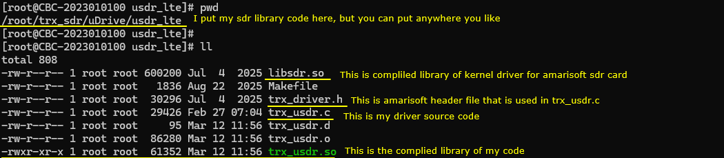
The next thing to verify is the Amarisoft execution directory, because this is the place where the main application loads the external TRX driver at runtime. In this example, the important point is not where the driver was originally built, but whether the Amarisoft side can correctly see and load the final shared library.
As shown in this directory listing, the Amarisoft enb directory contains the main executable files such as lteenb, supporting shared libraries, configuration folders, and the external TRX driver libraries. Among them, the most important file for this validation is trx_usdr.so.
In this setup, trx_usdr.so is not copied directly into the directory as a standalone file. Instead, it is created as a symbolic link pointing to the actual compiled driver library located at /root/trx_sdr/uDrive/usdr_lte/trx_usdr.so. This is a convenient way to keep the build output in the project directory while still allowing Amarisoft to load it from its own execution directory. It also makes rebuild and update easier, because once the target library is rebuilt in the project directory,
the Amarisoft side automatically sees the updated version through the symbolic link.
You can also see another symbolic link for libsdr.so, which points to /root/trx_sdr/libsdr.so. This means the Amarisoft runtime environment is prepared so that both the lower SDR access library and the custom TRX driver library are visible from the same execution directory. This is important because trx_usdr.so depends on the lower SDR library to communicate with the Amarisoft SDR card.
So, for validation, one of the first checks is to confirm that the symbolic link trx_usdr.so exists in the Amarisoft directory and that it points to the correct compiled library. If this link is missing, broken, or pointing to an outdated file, Amarisoft may fail to load the driver or may load the wrong version. Once this symbolic link is confirmed, the runtime side is properly connected to the compiled driver, and we can move on to the next validation step.
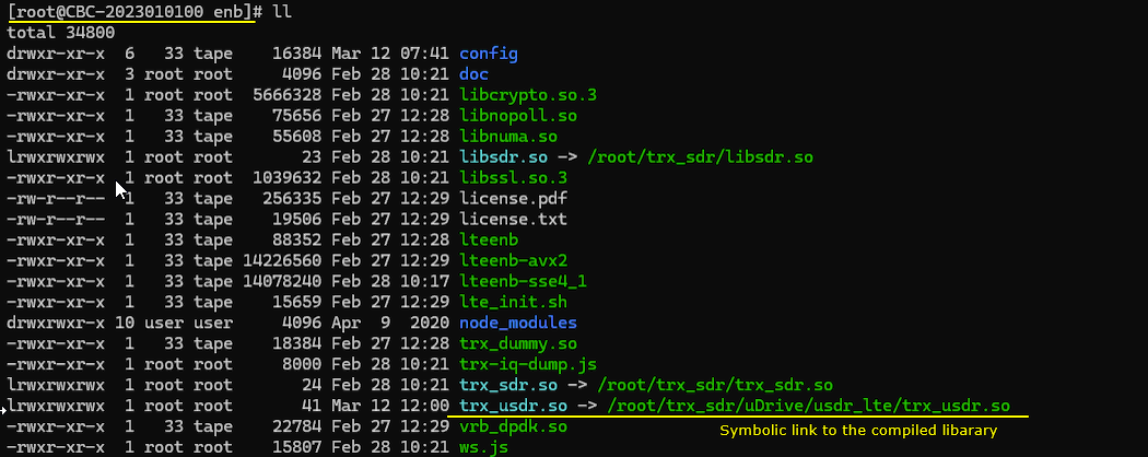
Create an eNB configuration file that explicitly loads trx_usdr.so as the external TRX driver. In other words, the configuration file should be prepared so that when Amarisoft starts, it does not use the default internal radio path or another sample driver such as trx_dummy.so. Instead, it should load trx_usdr.so, pass the required driver parameters to it, and use that driver as the RF interface for the LTE eNB.
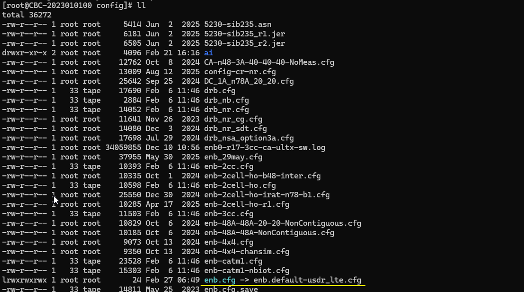
As a test UE, I used Amarisoft UEsim. This is a convenient choice for validation because it provides a controlled UE-side environment that is fully compatible with the Amarisoft eNB side. By using UEsim, the validation can focus on whether the custom TRX driver, the SDR access layer, and the eNB configuration are working correctly together, without introducing additional uncertainty from third-party UE hardware.
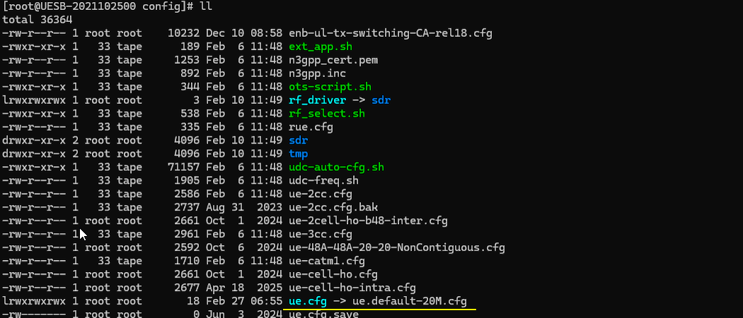
Following is the first part of the eNB configuration defines the basic LTE operating mode and the RF driver connection. The macro settings at the top select FDD operation, 20 MHz bandwidth, single antenna on both downlink and uplink, and disable the channel simulator. This means the setup is intended to use a real RF path with a simple SISO configuration.
The most important part in this section is the rf_driver block. It tells Amarisoft to use the external USDR-based driver, which maps to trx_usdr.so. The args: "dev0=/dev/sdr0" line specifies the SDR device used by the lower library. Other fields such as sample_hw_fmt, rx_antenna, sync, and clock are additional driver-related parameters that can be passed from the configuration file to the driver and confirmed
through the debug log.
This section also includes initial timing and RF settings such as FIFO timing, TX gain, and RX gain. These values are useful not only for operation, but also for validation, because they let you confirm that parameter exchange between Amarisoft and trx_usdr.so is working properly. In short, this first part of the configuration is where the eNB is bound to the custom driver and where the main radio characteristics of the test setup are defined.
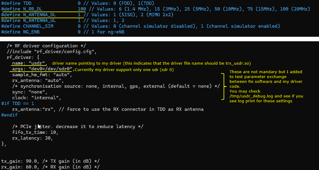
This part is the eNB cell configuration. It defines the identity and radio parameters of the LTE cell that the eNB will broadcast. In this example, the configuration sets the downlink EARFCN that determines the operating frequency of the cell.
Since this setup is configured for FDD, the active parameter is dl_earfcn: 2525, which corresponds to a downlink center frequency of 881.5 MHz in Band 5. The other EARFCN values shown in the file are just alternative examples for different LTE bands and frequencies. As you noted, you can configure any frequency as long as it matches your intended test setup and the UE configuration.
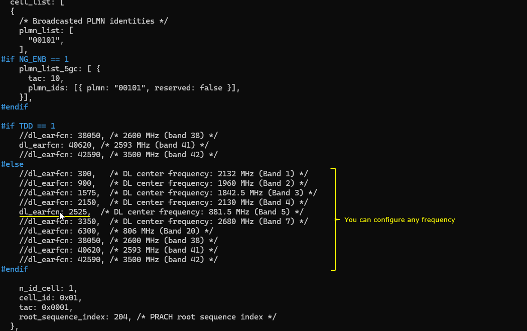
This is the UE configuration used for Amarisoft UEsim. There is nothing particularly special in this section. The main point is simply to configure the UE so that its key radio parameters match the eNB configuration.
In this example, the important settings are the bandwidth, the downlink EARFCN, and the antenna configuration. Since the eNB is configured with dl_earfcn: 2525 and single antenna operation, the UE is also configured with the same frequency and matching antenna setup. This ensures that the UE searches on the correct LTE carrier and uses a compatible radio configuration.
So for validation, the main thing to check on the UE side is that the frequency and antenna-related settings are aligned with the eNB. Once those basic parameters match, UEsim can be used as a clean test UE for verifying that the eNB and the custom TRX driver are working properly together.
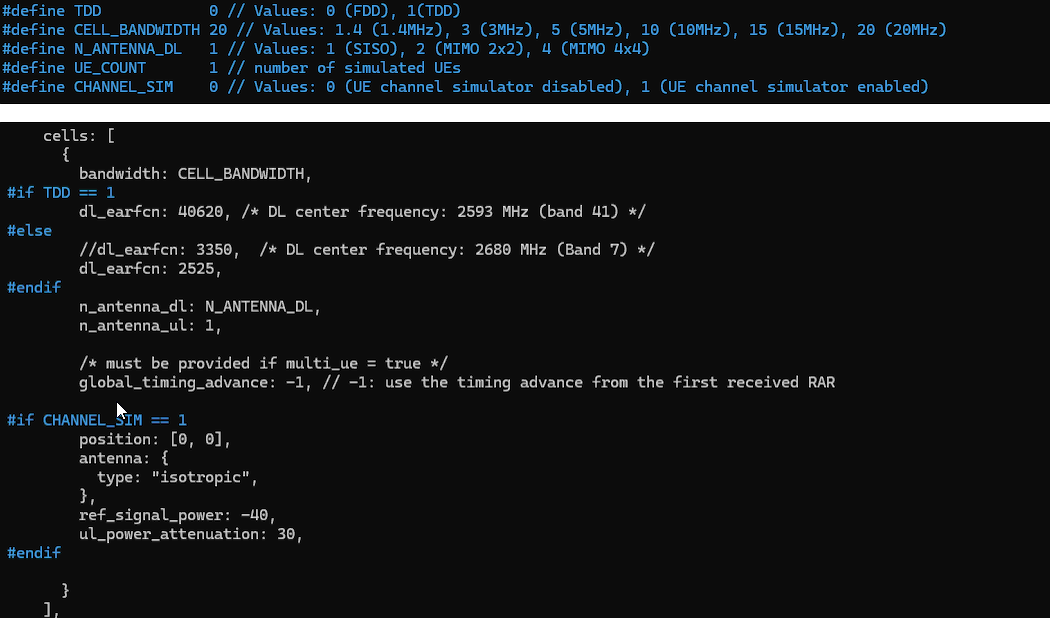
To begin the basic validation, run service lte restart on the Callbox side and check whether the eNB starts normally with your custom driver. At this stage, the goal is not to verify the full attach procedure yet. The goal is to confirm that the basic RF and driver settings are being loaded correctly.
In the console output, the first thing to check is whether trx_usdr.so is loaded successfully. In this example, that is confirmed by the message showing USDR: Driver initialized. This means the custom driver was found, loaded, and initialized by Amarisoft.
Next, check the RF summary line. Here, the output shows sample_rate=30.720 MHz, dl_freq=881.500 MHz, and ul_freq=836.500 MHz. These values should match the LTE bandwidth and EARFCN configured in the eNB configuration. Since the setup uses Band 5 with dl_earfcn: 2525 and 20 MHz bandwidth, this output confirms that the frequency and sampling rate were interpreted correctly.
Then check the startup message from the driver. The line USDR: Started with sample_rate=30.72 MHz, tx_channels=1, rx_channels=1 confirms that the driver moved beyond initialization and entered the running state. It also confirms that the current setup is single-channel TX and RX, which matches the SISO configuration in the config file.
You should also verify that the configured gain values are reflected by the application. In this example, the console shows tx_gain 60 and rx_gain 30. These are useful checkpoints because they show that the Amarisoft side has parsed the RF gain settings and is ready to forward them to the driver. For more detailed confirmation, you can also check /tmp/usdr_debug.log and see whether the driver printed the corresponding gain-related log messages.
So, after running service lte restart, the main checks are simple. Confirm that the driver is initialized, confirm that the sample rate and frequencies match the configuration, confirm that TX and RX channel counts are correct, confirm that the gain settings are applied, and confirm that the cell parameters shown by Amarisoft match the intended LTE setup. If all of these are correct, the basic eNB-side validation is successful and you can move on to UE-side connection testing.
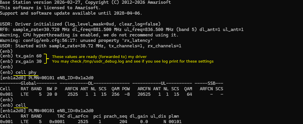
You can also run rf_info on the eNB console to verify the RF settings seen by Amarisoft at runtime. This is a useful cross-check because it shows the values that the upper software stack is currently using for the TRX interface.
In this example, the output shows TRX API version 15, which confirms that the application and the driver are communicating through the expected TRX API version. It also shows the TX and RX channel information, including gain and frequency. Here, TX0 is configured with 90.0 dB gain at 881.500000 MHz, and RX0 is configured with 60.0 dB gain at 836.500000 MHz. These values match the configuration and indicate that the settings
are already prepared and handed over to the driver side.
The line Sample format: tx=CF32 rx=CF32 also confirms the sample format currently used for both transmit and receive. This gives another useful validation point, because it shows how Amarisoft is treating the sample stream at the TRX boundary.
So, rf_info is a convenient runtime check for confirming that the configured frequency, gain, and sample format are correctly reflected by the eNB. If needed, you can compare these values with the messages in /tmp/usdr_debug.log to make sure the same settings are also visible inside your custom driver.
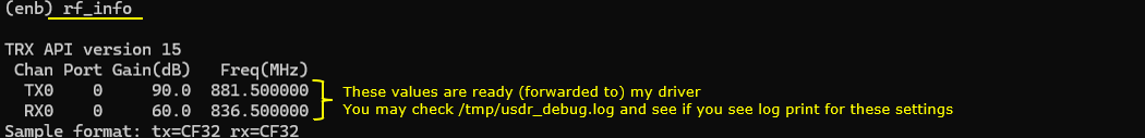
Now run service lte restart on the UEsim side, then adjust tx_gain, rx_gain, and execute power_on. At this stage, the purpose is to see whether the UE can detect the LTE cell that is being transmitted by the eNB through trx_usdr.so.
If you see the message Cell 0: SIB found, that is the first good sign. It means the UE has successfully detected the cell and decoded the broadcast system information. In practical terms, this shows that the eNB is transmitting the broadcast signal correctly through your custom TRX driver and that the UE is able to receive and interpret it.
This is an important checkpoint in validation because it proves that the basic over-the-air path is already working. Up to this point, the earlier checks only confirmed that the configuration, frequency, gain, and driver loading looked correct on the software side. But seeing Cell 0: SIB found confirms something more important. It confirms that real RF transmission and reception are happening correctly enough for the UE to detect and decode the LTE broadcast channel.
So if this message appears, you can conclude that the basic RF chain between the Amarisoft eNB, trx_usdr.so, the SDR hardware, and the Amarisoft UEsim is functioning properly. That is the first major success point in the end-to-end validation.
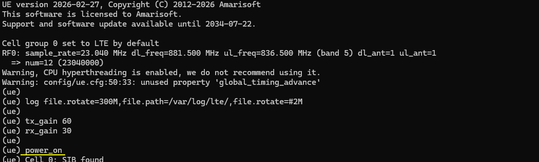
You can also check the trace log on the eNB side. If the trace shows normal LTE activity after the UE powers on, it is a strong indication that the driver is working properly not just for broadcast transmission, but also through the initial access procedure.
In this example, the trace already shows PRACH activity, including timing advance and SNR information. This means the eNB has successfully received the UE�s random access preamble through the RF path. That is an important result, because it confirms that the uplink path through trx_usdr.so is also working, not only the downlink broadcast path.
The following trace lines show normal uplink and downlink measurements for the UE, including identifiers such as RNTI, channel quality values, MCS, block rate, SNR, and timing-related parameters. When these values continue to appear normally, it strongly suggests that the driver is handling both TX and RX sample transfer correctly during the early LTE connection procedure.
So, if you see normal trace activity like this after the UE finds the SIB and starts access, it is highly likely that the driver is working fine throughout the initial attach stage. In other words, the TRX path is not only loading correctly, but is also carrying real LTE signaling successfully in both directions.
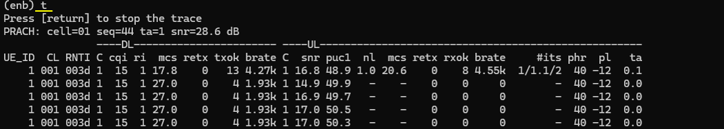
This screen shows that the initial attach signaling went through properly. The important point here is not to analyze each individual log line, but to confirm at a high level that the normal LTE attach sequence completed without any obvious failure in the signaling flow.
From the message sequence, you can see the expected progression of events such as RRC connection setup, NAS attach request, authentication exchange, security mode procedure, and attach accept. Since these signaling steps appear in the normal order, it indicates that the eNB, the UE, and the core-side signaling path are all working together correctly.
For the purpose of validating trx_usdr.so, this is a very important result. It shows that the custom TRX driver is not only able to support basic broadcast transmission and cell detection, but is also stable enough to carry the full initial attach signaling path successfully. In other words, both downlink and uplink sample transfer are functioning properly through the driver during real LTE control-plane operation.
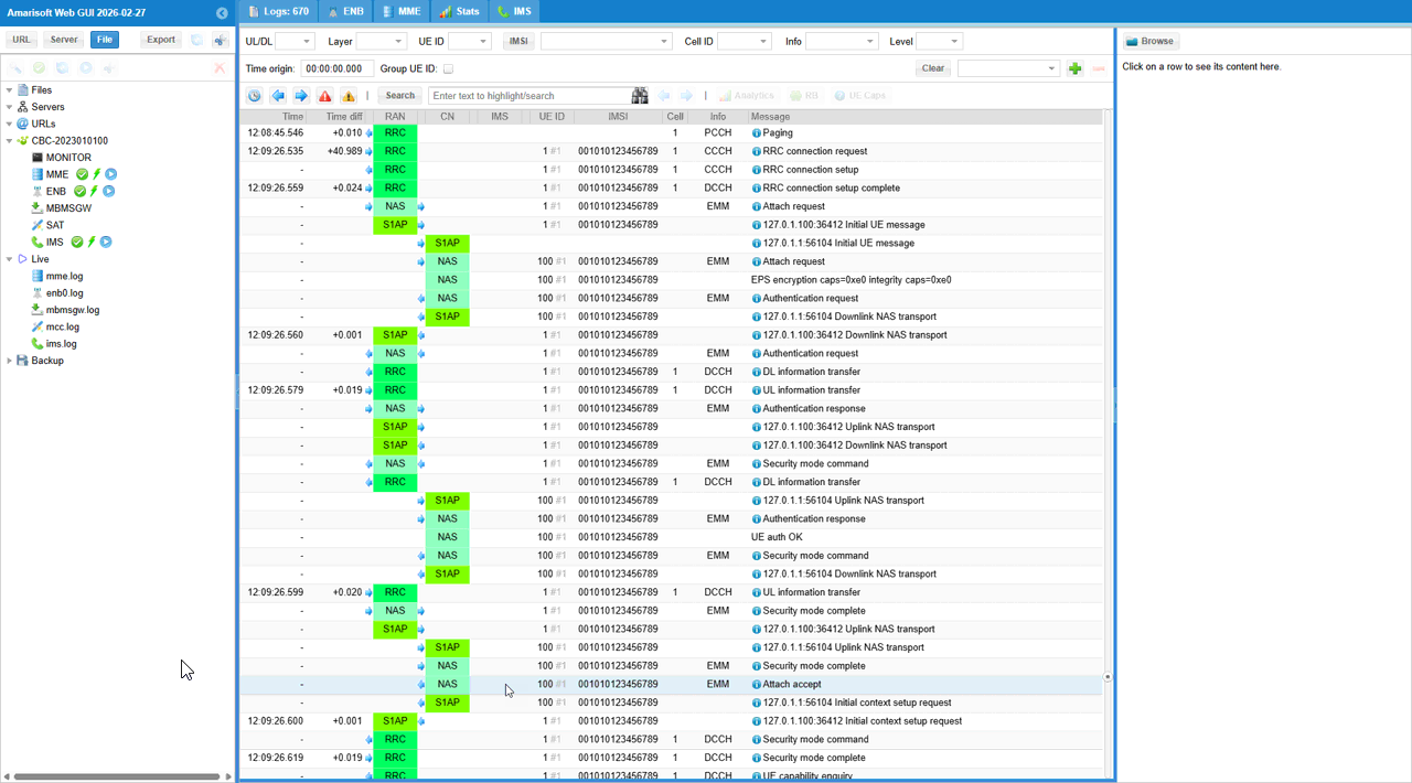
For debugging and validation purposes, I added log printing inside trx_usdr, and the output is saved as /tmp/usdr_debug.log. This log file is useful because it lets you confirm that the configuration parameters and runtime events seen at the Amarisoft side are actually reaching the custom driver code.
As shown here, the file usdr_debug.log is created under /tmp along with the other Amarisoft-related log files. This makes it easy to check driver-specific behavior separately from the normal eNB, MME, or IMS logs. In particular, this file is helpful for validating parameter exchange, driver initialization, start-up sequence, gain settings, frequency settings, and other callback activity inside trx_usdr.so.
So when validating the project, this log file becomes an important checkpoint. If the eNB console shows that settings such as gain, frequency, or sample rate are prepared, you can look in /tmp/usdr_debug.log and verify that the same values were also printed by the driver. This gives a direct way to confirm that the custom driver is not only loaded, but is also receiving and processing the expected parameters and function calls correctly.
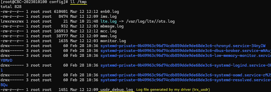
This is an example of the debug log generated by trx_usdr.so and saved in /tmp/usdr_debug.log. It shows that the driver was loaded correctly, the initialization function was called with the expected TRX API version, and the configuration parameters from the Amarisoft side were successfully passed into the driver. You can see values such as driver name, device argument, sample format, RX antenna, FIFO timing, sync source, and clock source printed in the log, which confirms that the parameter exchange path is working properly.
The log also shows the main runtime flow inside the driver. It records the sample-rate calculation for the configured LTE bandwidth, the start of the driver with the expected TX and RX channel counts, the RX and TX frequencies coming from TRXDriverParams2, and the successful hardware initialization and SDR start through libsdr. This is useful because it confirms that the driver moved beyond simple loading and actually reached the point of hardware startup.
In addition, the log shows gain-related activity such as default gain adjustment and later runtime calls to usdr_set_tx_gain, usdr_set_rx_gain, usdr_get_tx_gain, and usdr_get_rx_gain. These messages confirm that the gain values configured on the Amarisoft side are really being forwarded into the custom driver. So this log file serves as a direct validation tool. It lets you confirm that the driver is loaded, that the startup sequence is executed, and that important runtime parameters are actually reaching the code inside trx_usdr.so.
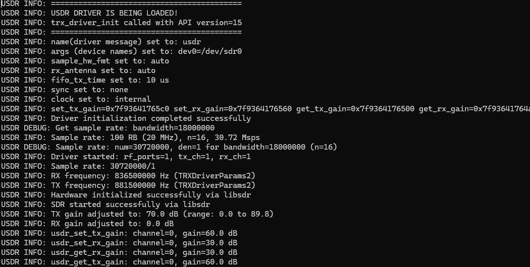
/*
* Initializes the TRX driver with a given TRXState.
* This function checks for ABI compatibility between the LTEENB and the TRX driver. If there's a mismatch, it logs an error message and returns -1 to indicate failure.
* On success, it allocates and initializes a TRXDummyState structure, setting its `dump_max` field based on a parameter.
* It then updates the TRXState with pointers to dummy functions for various operations (end, write, read, start, get_sample_rate), effectively setting up the TRX driver to use these dummy
* implementations.
* Returns 0 on successful initialization.
* The critical part of this function is to map the user defined function to TRX API template function pointer
* - `s1->opaque` is assigned to `s`, linking the TRX driver state with a user-defined structure for internal use.
* - The next lines assign dummy functions to the TRX driver's operational callbacks:
* - trx_dummy_end maps to `trx_end_func` for ending a TRX session,
* - trx_dummy_write maps to `trx_write_func2` for writing data,
* - trx_dummy_read maps to `trx_read_func2` for reading data,
* - trx_dummy_start maps to `trx_start_func2` for starting a TRX session,
* - trx_dummy_get_sample_rate_func maps to `trx_get_sample_rate_func` for getting the sample rate.
* These assignments ensure that the TRX driver operates with predefined dummy behaviors for critical operations.
*/