NR SA UL MIMO
The purpose of this tutorial is to show you how to configure and test UL MIMO for NR SA. At this point, I don't have any commercial UE supporting UL MIMO. So the first test is with Amari Callbox and Amari UEsim and I will add the test with commercial UE as soon as I managed to get a commercial UE.
When you want to try UL MIMO test with your own UE, make it sure that your UE really support UL MIMO and the UE declare the support of UL MIMO in UE capability Information as shown in Precondition section.
Even though the configuration for UL MIMO in Amarisoft gNB is designed to be pretty simple, you need to have detailed understandings on 3GPP lower layer specification if you want to configure the test condition exactly as you intended. The specification you need through understanding for this test are summarized as follows :
- Precoding Matrix : 38.211 - Table 6.3.1.5-1 ~ Table 6.3.1.5-7
- Precoding and number of layers : 38.212 - Table 7.3.1.1.2-2 ~ Table 7.3.1.1.2-5
- Antenna Port : 38.212 - Table 7.3.1.1.2-6 ~ Table 7.3.1.1.2-23
Table of Contents
- NR SA UL MIMO
- Introduction
- Summary of the Tutorial
- Test Setup
- Preconditions
- Key Configuration Parameters
- Test 1 : Reference Test - UL SISO
- Test 2 : UL MIMO - 2x2
- Test 3 : UL MIMO - 4x4
- Test 4 : UL MIMO - 2x2 : TPMI
- Configuration
- Perform the Test
- Log Analysis
- SubTest 1 : Index 0
- SubTest 2 : Index 2
- SubTest 3 : Index 4
- SubTest 4 : Index 6
- SubTest 5 : Index 8
- RRC / NAS Signaling
Introduction
Uplink Multiple-Input Multiple-Output (UL MIMO) technology in 5G New Radio Standalone (NR SA) networks represents a significant advancement in wireless communication, enabling enhanced throughput, spectral efficiency, and reliability by utilizing multiple antennas at both the User Equipment (UE) and the base station (gNB). UL MIMO leverages advanced signal processing techniques and 3GPP-defined procedures to allow simultaneous transmission of multiple data streams from the UE to the network, thereby maximizing the use of available radio resources. In the context of 5G NR, the configuration and testing of UL MIMO require a comprehensive understanding of key physical layer concepts such as precoding matrices, antenna port mapping, and the relationship between transmission layers and supported features as defined in 3GPP specifications (notably TS 38.211 and TS 38.212). This tutorial provides a structured approach to configuring and testing UL MIMO using Amarisoft's Callbox and UEsim, offering both practical steps for lab validation and theoretical background to ensure test accuracy. Mastery of these concepts is essential, as the implementation and validation of UL MIMO directly influence network performance and UE capability validation, impacting the broader 5G ecosystem where efficient use of uplink resources is critical for emerging applications and services.
-
Context of UL MIMO in 5G NR SA
- 5G NR introduces native support for advanced MIMO schemes, including uplink MIMO, as part of the effort to achieve higher data rates and improved link reliability.
- Standalone (SA) operation enables 5G networks to operate independently from LTE, fully utilizing NR features such as flexible spectrum allocation, advanced antenna techniques, and dynamic resource management.
- Amarisoft Callbox and UEsim provide a controlled test environment to emulate both gNB and UE, facilitating feature verification prior to commercial UE availability.
-
Relevance and Importance of UL MIMO Testing
- Ensuring UL MIMO is properly configured and validated is crucial for achieving the expected performance gains in uplink throughput and spectral efficiency.
- Understanding the interplay between 3GPP-defined configurations (e.g., precoding matrices, antenna ports, number of layers) is essential for accurate test execution and troubleshooting.
- Verification with commercial UE is a critical step toward deployment readiness and device interoperability in real-world 5G networks.
-
Learning Outcomes
- Acquire practical skills in configuring UL MIMO scenarios using Amarisoft test equipment.
- Gain a solid grasp of the lower-layer 3GPP specifications relevant to UL MIMO operation (notably TS 38.211 and TS 38.212).
- Develop the ability to analyze and interpret UE capability signaling and gNB configuration relevant to uplink MIMO.
- Build confidence in troubleshooting and validating advanced 5G NR features in a lab setting.
-
Prerequisites
- Fundamental understanding of 5G NR architecture and physical layer concepts.
- Familiarity with Amarisoft Callbox and UEsim operation is highly recommended.
- Working knowledge of 3GPP specifications, particularly TS 38.211 (Physical channels and modulation) and TS 38.212 (Multiplexing and channel coding).
- Basic experience with wireless test equipment and network configuration.
Summary of the Tutorial
This tutorial demonstrates a series of uplink MIMO (Multiple Input Multiple Output) test procedures using Amarisoft Callbox and UEsim for 5G NR Standalone (SA) scenarios. The tests progress from a reference uplink SISO (Single Input Single Output) configuration to 2x2 and 4x4 UL MIMO, including a case focused on TPMI (Transmit Precoding Matrix Indicator). The following summarizes the procedures, steps, and methodologies used in each test.
-
Preconditions
- Verify that the UE (Device Under Test) supports UL MIMO. This is typically checked via the UE capability information, ensuring support for multiple MIMO layers, proper subcarrier spacing, bandwidth, SRS (Sounding Reference Signal) resources, and higher-order modulation (e.g., 256QAM).
-
Key Configuration Parameters
- Familiarize with the following parameters, which are critical for all tests:
- srs_resource: Pay attention to n_ports (number of SRS ports).
- pusch: Key settings include max_rank (maximum MIMO rank/layers) and n_layer (number of transmission layers).
- Familiarize with the following parameters, which are critical for all tests:
-
Test 1: Reference Test - UL SISO
-
Configuration Steps:
- On the gNB, use a configuration file (gnb-sa-ulsiso.cfg) set up for SISO (N_ANTENNA_UL = 1, USE_SRS = 1).
- Enable SRS, ensure n_ports for SRS matches the number of UL antennas.
- Set PUSCH max_rank and n_layer to 1.
- Force the scheduler to allocate all possible UL slots with a fixed MCS for throughput comparison.
- Optionally, extend inactivity_timer to observe PHY throughput.
- On UEsim, match the UL and DL antenna settings to the gNB configuration.
-
Test Execution:
- Verify cell and uplink configuration (number of UL antennas, layers, RX channels, and ports).
- Power on the UE and ensure it attaches successfully.
- Observe and record the uplink throughput for reference.
-
Log Analysis:
- Confirm PUSCH maxRank = 1 in configuration.
- Check SRS resource configuration (should be port1 for SISO).
- At the PHY layer, verify antenna_ports and number of layers (nl = 1 indicates SISO).
-
Configuration Steps:
-
Test 2: UL MIMO - 2x2
-
Configuration Steps:
- On the gNB, use a configuration file for 2x2 MIMO (gnb-sa-ulmimo.cfg), set N_ANTENNA_UL = 2, USE_SRS = 1.
- Set SRS n_ports = 2 and PUSCH max_rank, n_layer = 2.
- Force scheduler for all UL slots with fixed MCS.
- Extend inactivity_timer if needed.
- On UEsim, set both UL and DL antennas to 2.
-
Test Execution:
- Verify the cell's uplink configuration (2 antennas/layers, 2 RX channels).
- Power on UE, ensure attach, and check if throughput improves compared to SISO.
-
Log Analysis:
- Confirm PUSCH maxRank = 2.
- SRS nrofSRS-Ports = 2.
- At the PHY layer, check antenna_ports, precoding_info, and nl = 2 (indicating 2-layer transmission).
-
Configuration Steps:
-
Test 3: UL MIMO - 4x4
-
Configuration Steps:
- On the gNB, use a configuration file for 4x4 MIMO (gnb-sa-ulmimo-4x4.cfg), set N_ANTENNA_UL = 4, USE_SRS = 1.
- Set SRS n_ports = 4 and PUSCH max_rank, n_layer = 4.
- Force scheduler and extend inactivity_timer as needed.
- On UEsim, match UL and DL antennas to 4.
-
Test Execution:
- Verify proper cell configuration (4 antennas/layers, 4 RX channels).
- Power on UE, ensure attach, and compare throughput with SISO/2x2.
-
Log Analysis:
- Confirm PUSCH maxRank = 4.
- SRS nrofSRS-Ports = 4.
- At the PHY layer, check antenna_ports, precoding_info, and nl = 4 (indicating 4-layer transmission).
-
Configuration Steps:
-
Test 4: UL MIMO - 2x2 with TPMI
-
Configuration Steps:
- On the gNB, use gnb-sa-ulmimo-tpmi.cfg for 2x2 MIMO with TPMI configuration.
- Set N_ANTENNA_UL = 2, USE_SRS = 1, SRS n_ports = 2.
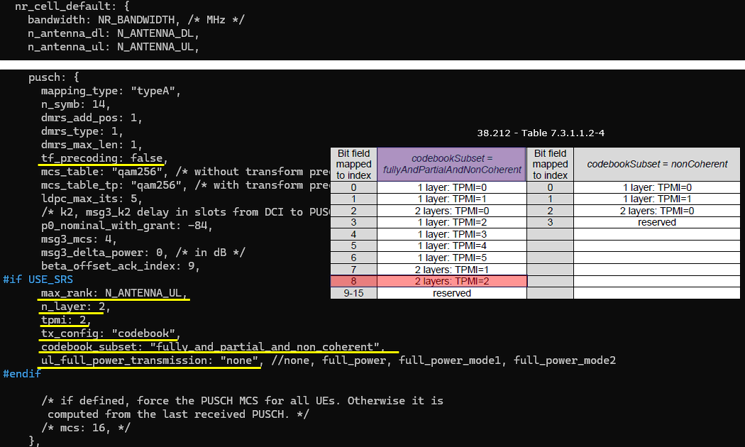
- Configure PUSCH with tx_config: "codebook", n_layer: 1, and tpmi: 2.
- Set codebook_subset to "fully_and_partial_and_non_coherent" to use the full range of 3GPP-defined codebook entries.
- Force scheduler and extend inactivity_timer as before.
- On UEsim, match antenna settings to gNB.
-
Test Execution:
- Verify uplink configuration (2 antennas/layers, 2 RX channels).
- Power on UE, ensure attach, and observe throughput.
-
Log Analysis:
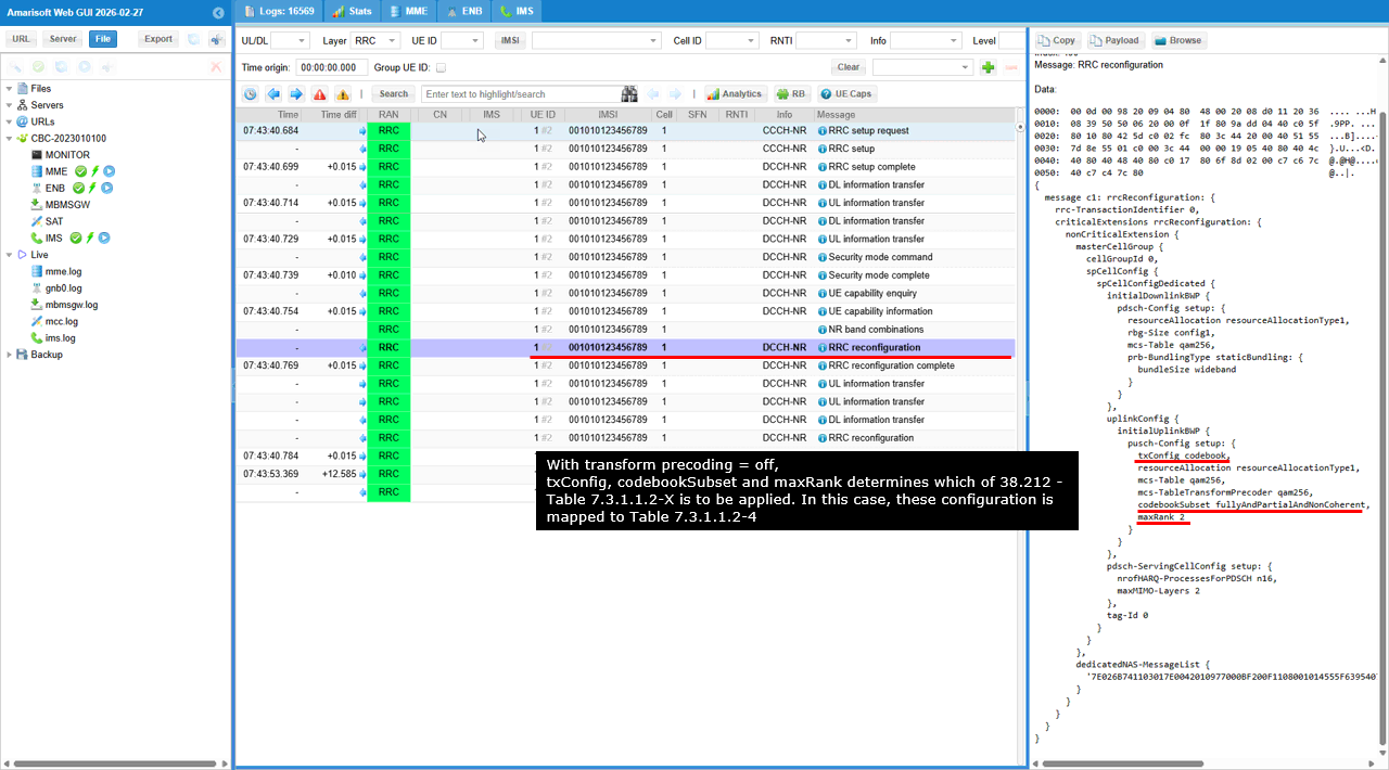
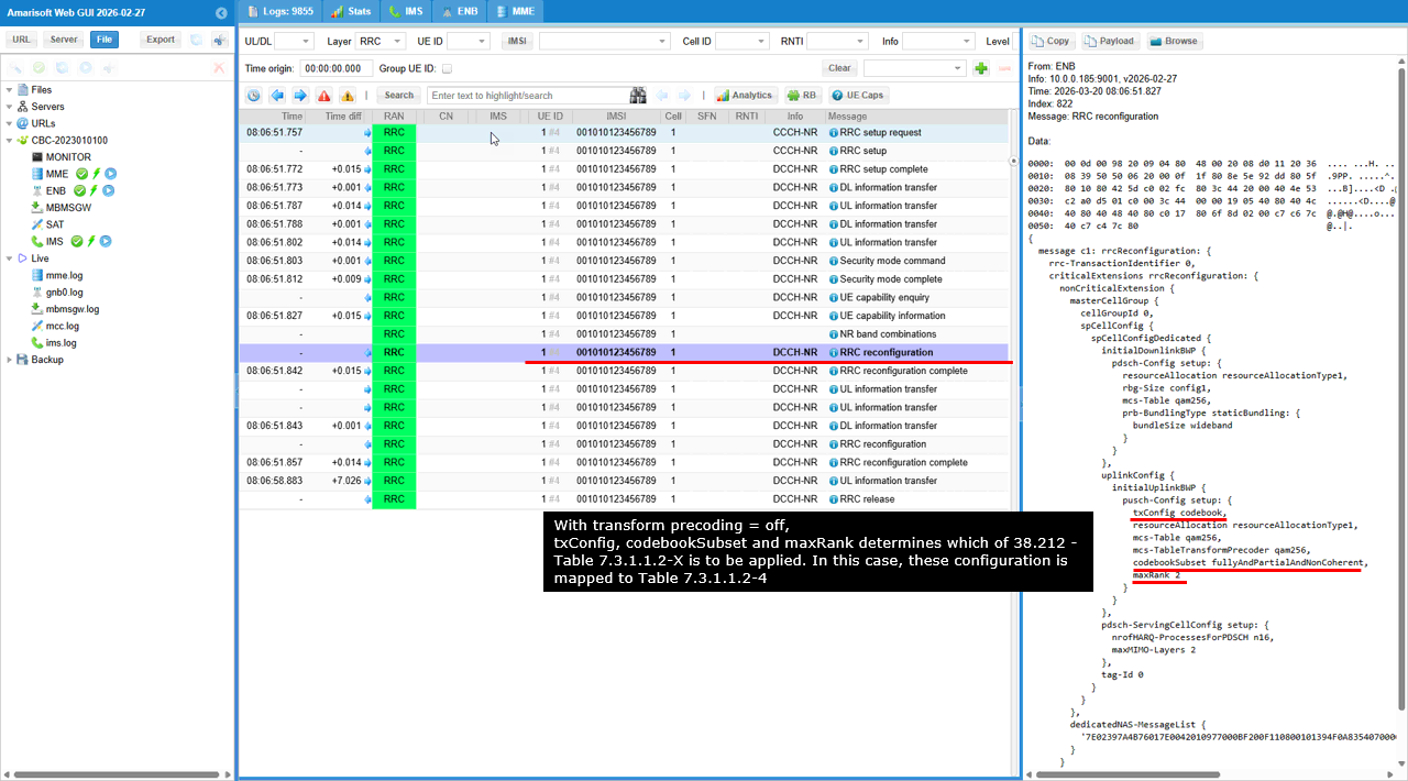
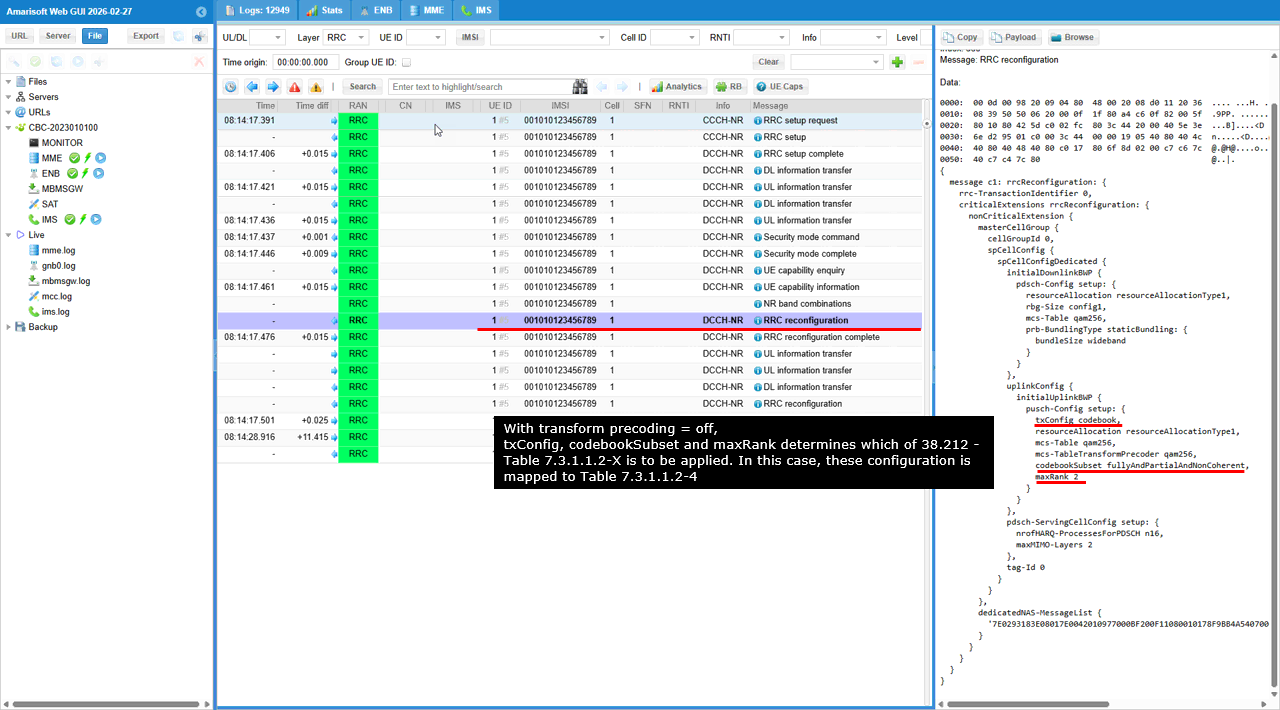
- Confirm RRC setup configures txConfig as codebook-based, transformPrecoding disabled (CP-OFDM).
- Check codebookSubset and maxRank (should indicate codebook-based MIMO with max 2 layers).
- In DCI 0_1, ensure precoding_info matches the expected TPMI, confirming the UE is scheduled with the intended codebook index.
-
Configuration Steps:
General Methodology:
- For each test, ensure that the gNB and UEsim configurations match in terms of antenna numbers and SRS resources.
- Validate cell and uplink configuration using cell and RF info commands before starting the UE.
- After test execution, analyze logs to confirm that the intended MIMO configuration, SRS ports, and codebook/precoder selection are correctly applied and signaled to the UE.
Test Setup
Test setup for this tutorial is as shown below.

Preconditions
Before running the test in this tutorial, make sure that your UE, or DUT, supports UL MIMO. One simple way to check this is to look at the UE Capability Information message and confirm whether the UE declares UL MIMO capability.
In this example, the relevant information is shown under featureSetsUplinkPerCC. The UE supports 30 kHz uplink subcarrier spacing and 20 MHz uplink bandwidth in FR1. More importantly, the UE declares mimo-CB-PUSCH capability, and maxNumberMIMO-LayersCB-PUSCH is set to twoLayers. This indicates that the UE supports codebook-based PUSCH transmission with up to two uplink MIMO layers.
The parameter maxNumberSRS-ResourcePerSet is set to 1. This means that one SRS resource can be configured per SRS resource set for this feature set. The UE also declares supportedModulationOrderUL as qam256, meaning that 256QAM is supported for uplink transmission.
featureSetsUplinkPerCC {
{
supportedSubcarrierSpacingUL kHz30,
supportedBandwidthUL fr1: mhz20,
mimo-CB-PUSCH {
maxNumberMIMO-LayersCB-PUSCH twoLayersmaxNumberSRS-ResourcePerSet 1
},
supportedModulationOrderUL qam256
}
},
Key Configuration Parameters
Followings are important configuration parameters for this tutorial. You may click on the items for the descriptions from Amarisoft documents.
Test 1 : Reference Test - UL SISO
This test is not for UL MIMO, but I decided to perform this test as a reference (i.e, comparative purpose with the test result for MIMO case) before trying UL MIMO. It would be helpful to understand the concept of UL MIMO if you compare this reference with other test cases.
Configuration
I used the gnb-sa-ulsiso.cfg on gNB which is copied and modified from gnb-sa.cfg

In gnb-sa-ulsiso.cfg , the configuration is done as follows.
This test is configured as UL SISO, so N_ANTENNA_UL is set to 1. This means that the UE uses only one uplink transmit antenna path for PUSCH transmission.
USE_SRS is also set to 1 to enable SRS. Strictly speaking, SRS is not mandatory for this UL SISO reference test, but I enabled it so that the configuration can be compared more easily with the later UL MIMO test case. #define N_ANTENNA_UL 1 configures the uplink as SISO.#define USE_SRS 1 enables periodic SRS. In the Amarisoft configuration, when N_ANTENNA_UL is greater than or equal to 2, uplink SU-MIMO can also be enabled together with SRS. In this reference test, however, N_ANTENNA_UL is set to 1, so the test remains UL SISO even though SRS is enabled.

This part of the configuration is not mandatory for UL SISO itself, but I enabled it to make the throughput comparison easier between this UL SISO reference test and the later UL MIMO test.
force_full_bsr: true forces continuous uplink scheduling as much as possible by making the gNB assume that the UE always has uplink data to transmit.
pusch_mcs: 2 fixes the PUSCH MCS to a very low value so that the test can run stably without frequent PUSCH CRC errors caused by RF condition or antenna connection quality.
The purpose of this setting is not to measure the maximum possible uplink throughput. The purpose is to create a stable and controlled test condition where UL SISO and UL MIMO can be compared more clearly. By forcing full-buffer uplink scheduling and using the same fixed MCS, it becomes easier to check whether the throughput difference comes from SISO or MIMO operation rather than from scheduler behavior or changing radio condition.

One important thing to note is that the number of SRS ports configured by n_ports should be the same as the number of uplink MIMO antennas configured by N_ANTENNA_UL.
n_ports: N_ANTENNA_UL configures the number of SRS antenna ports to be the same as the number of uplink antenna ports used for PUSCH transmission.
In this reference UL SISO test, N_ANTENNA_UL is set to 1, so n_ports also becomes 1. This means that only one SRS port is configured, and the UE transmits SRS through a single uplink antenna path.
resource_type: "periodic" configures the SRS as periodic SRS, so the UE transmits SRS repeatedly according to the configured period.
period: 80 configures the SRS transmission period as 80 slots. This means that the UE periodically transmits SRS every 80 slots.
srs_resource_id_list: [ 0 ] assigns SRS resource ID 0 to the SRS resource set. Since this is the SISO reference case, only one SRS resource is used.
In the later UL MIMO test, N_ANTENNA_UL is increased, and n_ports should follow that value. This allows the gNB to configure SRS with the same number of ports as the uplink MIMO antenna configuration.

I also set max_rank and n_layer in the PUSCH configuration to the same value as the number of uplink antennas.
max_rank: N_ANTENNA_UL configures the maximum PUSCH rank to be the same as the number of uplink antennas. This value is reflected into the maxRank IE in PUSCH-Config in the RRC message.
n_layer: N_ANTENNA_UL forces the gNB to schedule PUSCH with the same number of layers as the number of uplink antennas. This parameter is useful when you want to force a specific number of UL MIMO layers for the test.
One important thing to note is that n_layer is not mandatory for UL MIMO operation in Amarisoft Callbox. By default, UL MIMO can be configured based on the CSI report from the UE as long as the SRS ports are properly configured. In other words, if the UE reports a suitable uplink rank and the SRS configuration supports multiple ports, the gNB can schedule UL MIMO without explicitly forcing n_layer.
In this tutorial, I used n_layer because I wanted to force the gNB to apply UL MIMO regardless of the CSI report. This makes the test condition more deterministic and easier to compare with the UL SISO reference case.

This setting is not mandatory either, but I extended the inactivity timer so that the RRC connection can stay active long enough to check PHY throughput without generating IP throughput.
inactivity_timer: 60000 keeps the UE connection active for a long time even when there is no user-plane IP traffic. This is useful in this test because I want to observe the PHY-layer uplink throughput generated by forced UL scheduling, not the application-layer throughput generated by ping, iperf, or other IP traffic.
With this setting, the UE does not quickly go back to idle state, so I can keep monitoring the PUSCH scheduling result and PHY throughput for a longer period during the UL SISO and UL MIMO comparison test.

I used the ue-nr-sa-ulsiso.cfg on UEsim which is copied and modified from ue-nr-sa.cfg

In ue-nr-sa-ulsiso.cfg , the configuration is done as follows.
I set the number of UL and DL antennas in UEsim to the same values as the UL and DL antenna configuration in the Callbox gNB.
#define N_ANTENNA_DL 2 configures the number of downlink receive antenna paths in UEsim to match the downlink antenna configuration of the gNB.
#define N_ANTENNA_UL 1 configures the number of uplink transmit antenna paths in UEsim to match the uplink antenna configuration of the gNB. Since this is the UL SISO reference test, N_ANTENNA_UL is set to 1.
n_antenna_dl: N_ANTENNA_DL applies the configured downlink antenna number to the NR cell configuration in UEsim.
n_antenna_ul: N_ANTENNA_UL applies the configured uplink antenna number to the NR cell configuration in UEsim.
In this reference test, the gNB is configured with N_ANTENNA_UL set to 1, and UEsim is also configured with N_ANTENNA_UL set to 1. This makes the uplink side operate as SISO in both the Callbox and UEsim configuration.


Perform the Test
After starting the Callbox, first check whether the cell is configured as intended. The important part in this test is the uplink configuration, so I checked the number of UL antennas and the number of UL layers using the cell phy command. I also checked the enabled RX channel using the rf_info command.
cell phy shows the physical cell configuration currently used by the gNB. In this result, the UL ANT value is 1 and the UL NL value is also 1, which means that only one uplink antenna and one uplink layer are configured. This confirms that the cell is operating as UL SISO for this reference test.
rf_info shows the RF channel status of the Callbox. In this result, only RX0 is enabled, which matches the UL SISO configuration. Since only one uplink receive path is active, the gNB receives the UE uplink signal through a single RX channel.
So the key confirmation from this step is that the gNB is configured with one UL antenna, one UL layer, and one active RX path. This confirms that the reference test is really running as UL SISO before moving on to the UL MIMO test case.

Power on the UE in UEsim after confirming that the Callbox configuration is set as intended.
power_on starts the simulated UE operation in UEsim.
Cell 0: SIB found indicates that the UE successfully detected the NR cell and decoded the system information. This means that the UE can see the cell and the basic downlink broadcast channel configuration is working properly.
At this point, the UE has not completed the full registration yet, but this message confirms that the first step of cell detection and SIB decoding is successful.

After the UE completes registration, check the uplink throughput from the Callbox trace.
t starts the real-time Callbox trace and shows the DL and UL scheduling status for the connected UE.
PRACH: cell=01 seq=6 ta=2 snr=21.0 dB indicates that the UE successfully performed random access and that the received PRACH quality is good enough for the test.
In the UL part of the trace, mcs is fixed to 2.0 as configured by pusch_mcs: 2, and the UL bitrate is around 1.62M. Since this is the UL SISO reference test, this throughput can be used as the baseline value for later comparison with the UL MIMO test.
rxok shows the number of successfully received UL transport blocks, and the increasing rxok value confirms that PUSCH is being received successfully. brate shows the current uplink bitrate, and the stable value around 1.62M indicates that the forced full-buffer UL scheduling is working as intended.
Remember this UL throughput value as the reference result. In the later UL MIMO test, we can compare the UL MIMO throughput against this UL SISO throughput to check whether multiple-layer uplink transmission is actually applied.

Log Analysis
Now let�s look into the log and check how the configuration is reflected in the signaling message.
The first important thing to check is maxRank in pusch-Config of the RRC Setup message. Since this test is configured as UL SISO, maxRank is set to 1. maxRank: 1 indicates that the maximum allowed PUSCH transmission rank is 1, meaning that the UE can transmit only one uplink layer for PUSCH in this cell configuration. dmrs-UplinkForPUSCH-MappingTypeA setup indicates that the DMRS configuration for PUSCH mapping type A is included in the RRC Setup message. transformPrecoderDisabled setup indicates that this PUSCH configuration is used for CP-OFDM based uplink transmission without transform precoding. resourceAllocation resourceAllocationType1 indicates that PUSCH resource allocation type 1 is configured. codebookSubset nonCoherent indicates that the UE is configured to use the non-coherent codebook subset for codebook-based PUSCH transmission.
Since this is the UL SISO reference test, the most important point is that maxRank is 1. This confirms that the gNB RRC configuration allows only one PUSCH layer, which matches the intended UL SISO configuration.

Next, check the number of SRS ports. You can confirm this from nrofSRS-Ports in srs-ResourceToAddModList. In this test, nrofSRS-Ports is set to port1 because this is the UL SISO reference test.
nrofSRS-Ports port1 indicates that only one SRS port is configured for the UE. Since this test is configured with N_ANTENNA_UL set to 1, the SRS resource is also configured with one port, and this matches the intended UL SISO configuration. transmissionComb n2 indicates that the SRS uses a 2-comb transmission structure, combOffset-n2 0 indicates that comb offset 0 is used, and cyclicShift-n2 5 indicates the cyclic shift value used for this SRS resource. resourceMapping shows how the SRS is mapped in time and frequency, where startPosition 1, nrofSymbols n1, and repetitionFactor n1 indicate that the SRS is transmitted using one OFDM symbol without repetition. freqDomainPosition 0, freqDomainShift 5, and freqHopping define the frequency-domain position and hopping-related configuration of the SRS. groupOrSequenceHopping neither indicates that neither group hopping nor sequence hopping is used. resourceType periodic indicates that this SRS is periodically transmitted, and periodicityAndOffset-p s180: 7 indicates the configured SRS periodicity and offset. The key point in this section is nrofSRS-Ports port1, which confirms that the RRC SRS configuration uses only one SRS port, matching the one uplink antenna used in this UL SISO reference test.

Lastly, let�s check the operation at the PHY layer. The first thing to check is the antenna_ports field in DCI 0_1. The interpretation of this value is a little complicated, so refer to this note for the detailed interpretation of the field.
In this log, the selected PDCCH message is DCI 0_1 for uplink scheduling, and antenna_ports=0 indicates the antenna port configuration used for the scheduled PUSCH. Since this is the UL SISO reference test, the scheduled PUSCH is expected to use one layer and one antenna port configuration. time_domain_rsc=0 indicates the selected PUSCH time-domain resource allocation, mcs=2 indicates that the PUSCH MCS is fixed to 2 as configured by pusch_mcs: 2, ndi=0 indicates the new data indicator value for this transmission, rv_idx=0 indicates that redundancy version 0 is used, harq_process=1 indicates the HARQ process ID used for this PUSCH scheduling, dai=0 indicates the downlink assignment index value, tpc_command=1 indicates the transmit power control command included in the DCI, srs_request=0 indicates that this DCI does not trigger an aperiodic SRS request, dmrs_seq_init=0 indicates the DMRS sequence initialization value, and ul_sch_indicator=1 indicates that this DCI schedules UL-SCH transmission. The key point in this PHY-layer check is that the DCI is scheduling PUSCH with mcs=2 and antenna_ports=0 under the SISO configuration, which matches the intended reference test condition where the UE transmits uplink data using only one layer. (NOTE : Check out this note for the interpretation of this field.)

Next, check the number of layers used for PUSCH. The number of PUSCH layers is indicated by the nl field in the PUSCH log. In this case, the nl field is not printed in the log, and this means that the value of nl is 1 by default. Since nl=1 means that only one PUSCH layer is used, this confirms that the uplink transmission is operating as SISO. In the selected PUSCH log, harq=1 indicates the HARQ process used for this uplink transmission, prb=2:47 indicates the allocated uplink PRB range, symb=0:14 indicates that the PUSCH is allocated over the full 14 OFDM symbols in the slot, CW0 indicates that one codeword is used, tb_len=349 indicates the transport block size, mcs=2 indicates that the fixed low MCS configured by pusch_mcs: 2 is applied, and crc=OK indicates that the received PUSCH transport block is decoded successfully. The key point here is that nl is not explicitly shown, which means nl=1, and this matches the intended UL SISO reference condition where the UE transmits PUSCH using only one uplink layer.

Test 2 : UL MIMO - 2x2
This test is to show how to configure and validate UL 2x2 MIMO.
Configuration
I used the gnb-sa-ulmimo.cfg on gNB which is copied and modified from gnb-sa.cfg

In gnb-sa-ulmimo.cfg , the configuration is done as follows.
This test is configured as UL 2x2 MIMO, so N_ANTENNA_UL is set to 2. N_ANTENNA_UL: 2 configures two uplink antenna paths, which means the gNB can receive uplink transmission using 2x2 UL MIMO instead of UL SISO. USE_SRS: 1 enables periodic SRS, and this is important for UL MIMO because the gNB needs SRS from the UE to estimate the uplink channel condition for multiple uplink antenna ports. In the Amarisoft configuration comment, uplink SU-MIMO is enabled when N_ANTENNA_UL is greater than or equal to 2, but not all UEs support uplink SU-MIMO, so you should first confirm the UE capability before running this test.
The key configuration items are N_ANTENNA_UL: 2 and USE_SRS: 1. N_ANTENNA_UL: 2 changes the uplink configuration from SISO to 2x2 MIMO, and USE_SRS: 1 enables SRS so that the gNB can configure and operate UL MIMO properly.

This part of the configuration is not mandatory for UL MIMO itself, but I enabled it to make the throughput comparison easier between the previous UL SISO reference test and this UL 2x2 MIMO test. force_full_bsr: true forces continuous uplink scheduling as much as possible by making the gNB assume that the UE always has uplink data to transmit. pusch_mcs: 2 fixes the PUSCH MCS to a very low value so that the test can run stably without frequent PUSCH CRC errors caused by RF condition or antenna connection quality. By using the same forced full-buffer scheduling and the same fixed MCS as the UL SISO reference test, it becomes easier to compare the PHY throughput and check whether the throughput increase really comes from UL MIMO operation rather than from scheduler behavior, MCS variation, or changing radio condition.
One important thing to note is that the number of SRS ports configured by n_ports should be the same as the number of uplink MIMO antennas configured by N_ANTENNA_UL. n_ports: N_ANTENNA_UL configures the number of SRS antenna ports to follow the number of uplink antenna ports, so in this UL 2x2 MIMO test, N_ANTENNA_UL is set to 2 and n_ports also becomes 2. This means that the UE is configured to transmit SRS using two SRS ports, and this allows the gNB to estimate the uplink channel for two uplink antenna paths. resource_type: "periodic" configures the SRS as periodic SRS, so the UE transmits SRS repeatedly according to the configured period. period: 80 configures the SRS transmission period as 80 slots, meaning that the UE periodically transmits SRS every 80 slots. srs_resource_id_list: [ 0 ] assigns SRS resource ID 0 to the SRS resource set. The key point in this configuration is that n_ports follows N_ANTENNA_UL, because UL MIMO requires the SRS port configuration to match the number of uplink antenna ports used for the test.
I also set max_rank and n_layer in the PUSCH configuration to the same value as the number of uplink antennas, so both parameters follow N_ANTENNA_UL in this UL 2x2 MIMO test. max_rank: N_ANTENNA_UL configures the maximum PUSCH rank to be the same as the number of uplink antennas, and this value is reflected into the maxRank IE in PUSCH-Config in the RRC message. n_layer: N_ANTENNA_UL forces the gNB to schedule PUSCH with the same number of layers as the number of uplink antennas, so in this test the gNB
is forced to use two PUSCH layers for UL MIMO operation. One important note is that n_layer is not mandatory for UL MIMO operation in Amarisoft Callbox. By default, UL MIMO can be configured based on the CSI report from the UE as long as the SRS port is properly configured. However, if you want to force the gNB to apply UL MIMO regardless of the CSI report, you can use the n_layer parameter. In this tutorial, I used n_layer to make the test condition deterministic and easier to compare with the UL SISO reference
test. (
This setting is not mandatory either, but I extended the inactivity timer so that the connection can stay active long enough to check PHY throughput without generating IP throughput. inactivity_timer: 60000 keeps the UE in connected state for a long time even when there is no user-plane IP traffic, so the UE does not quickly move back to idle state while I am monitoring the forced UL scheduling result. This is useful in this test because I want to observe the PHY-layer uplink throughput produced by force_full_bsr and fixed PUSCH scheduling, not the application-layer throughput produced by ping, iperf, or other IP traffic. By keeping the connection active for a longer time, I can compare the UL SISO and UL 2x2 MIMO PHY throughput under a stable condition without continuously generating external traffic.
I used the ue-nr-sa-ulmimo.cfg on UEsim which is copied and modified from ue-nr-sa.cfg

In ue-nr-sa-ulmimo.cfg, the configuration is done as follows.
I set the number of UL and DL antennas in UEsim to the same values as the UL and DL antenna configuration in the Callbox gNB by setting N_ANTENNA_DL and N_ANTENNA_UL. N_ANTENNA_DL: 2 configures two downlink receive antenna paths in UEsim, matching the two downlink antenna configuration of the gNB. N_ANTENNA_UL: 2 configures two uplink transmit antenna paths in UEsim, matching the two uplink antenna configuration of the gNB for this UL 2x2 MIMO test. n_antenna_dl: N_ANTENNA_DL applies this downlink antenna value to the NR cell configuration in UEsim, and n_antenna_ul: N_ANTENNA_UL applies this uplink antenna value to the NR cell configuration in UEsim. The key point is that both the Callbox and UEsim should use the same UL antenna configuration. Since this test is intended for UL 2x2 MIMO, N_ANTENNA_UL is set to 2 on both sides, so the simulated UE can transmit PUSCH using two uplink antenna paths and the gNB can receive it as a 2-layer UL MIMO transmission.

Perform the Test
After starting the Callbox, first check whether the cell is configured as intended. The important part in this test is the uplink configuration, so I checked the number of UL antennas and the number of UL layers using the cell phy command, and I also checked the enabled RX channels using the rf_info command. In the cell phy result, the UL ANT value is 2 and the UL NL value is also 2, which means that two uplink antennas and two uplink layers are configured. This confirms that the cell is configured for UL 2x2 MIMO instead of UL SISO. In the rf_info result, both RX0 and RX1 are enabled, which means that two uplink receive paths are active in the Callbox. This matches the intended UL 2x2 MIMO configuration because the gNB needs two RX channels to receive the two uplink antenna paths from the UE. The key confirmation from this step is that the gNB is configured with two UL antennas, two UL layers, and two active RX paths, so the Callbox side is ready for the UL 2x2 MIMO test.

Power on the UE in UEsim after confirming that the Callbox is configured for UL 2x2 MIMO.
power_on starts the simulated UE operation in UEsim, and Cell 0: SIB found indicates that the UE successfully detected the NR cell and decoded the system information. This confirms that the UE can see the cell and that the basic downlink broadcast channel configuration is working properly. At this point, the UE has not completed the full registration yet, but this message confirms that the first step of cell detection and SIB decoding is successful before checking the actual UL MIMO operation.
After the UE completes registration, check the uplink throughput from the Callbox trace and compare it with the UL SISO reference throughput. t starts the real-time Callbox trace and shows the DL and UL scheduling status for the connected UE. PRACH: cell=01 seq=6 ta=2 snr=20.5 dB indicates that the UE successfully performed random access and that the received PRACH quality is good enough for this test. In the UL part of the trace, mcs is fixed to 2.0 as configured by pusch_mcs: 2, and the UL bitrate is around 3.25M. In the previous UL SISO reference test, the UL bitrate was around 1.62M with the same fixed MCS and forced full-buffer scheduling, so this result is almost double the SISO throughput. This throughput increase is the most direct indication that two-layer UL MIMO is being applied. rxok shows the number of successfully received UL transport blocks, and the increasing rxok value confirms that PUSCH is being received successfully. brate shows the current uplink bitrate, and the stable value around 3.25M confirms that the forced UL scheduling is working as intended under the UL 2x2 MIMO configuration. The key point is that the UL MIMO throughput is about two times higher than the UL SISO reference throughput, which confirms that the UE is transmitting PUSCH with two uplink layers instead of one.

Log Analysis
Now let�s look into the log and check how the UL 2x2 MIMO configuration is reflected in the signaling message. The first important thing to check is maxRank in pusch-Config of the RRC Setup message. Since this test is configured as UL 2x2 MIMO, maxRank is set to 2. maxRank: 2 indicates that the maximum allowed PUSCH transmission rank is 2, meaning that the UE can transmit up to two uplink layers for PUSCH in this cell configuration. dmrs-UplinkForPUSCH-MappingTypeA setup indicates that the DMRS configuration for PUSCH mapping type A is included in the RRC Setup message. transformPrecoderDisabled setup indicates that this PUSCH configuration is used for CP-OFDM based uplink transmission without transform precoding. resourceAllocation resourceAllocationType1 indicates that PUSCH resource allocation type 1 is configured. codebookSubset nonCoherent indicates that the UE is configured to use the non-coherent codebook subset for codebook-based PUSCH transmission. The key point in this section is that maxRank is 2, which confirms that the gNB RRC configuration allows two PUSCH layers and matches the intended UL 2x2 MIMO configuration.

Next, check the number of SRS ports. You can confirm it from nrofSRS-Ports in srs-ResourceToAddModList. In this test, nrofSRS-Ports is set to ports2 because this is the UL 2x2 MIMO test. nrofSRS-Ports ports2 indicates that two SRS ports are configured for the UE, and this matches N_ANTENNA_UL: 2 in the gNB configuration. This is important because the gNB needs two SRS ports to estimate the uplink channel for two uplink antenna paths and to support two-layer PUSCH transmission. transmissionComb n2 indicates that the SRS uses a 2-comb transmission structure, combOffset-n2 0 indicates that comb offset 0 is used, and cyclicShift-n2 0 indicates the cyclic shift value used for this SRS resource. resourceMapping startPosition 1, nrofSymbols n1, and repetitionFactor n1 indicate that the SRS is transmitted using one OFDM symbol without repetition. freqDomainPosition 0, freqDomainShift 5, and freqHopping define the frequency-domain position and hopping-related configuration of the SRS. groupOrSequenceHopping neither indicates that neither group hopping nor sequence hopping is used, and resourceType periodic with periodicityAndOffset-p s180: 7 indicates that this SRS is periodically transmitted with the configured periodicity and offset. The key point is nrofSRS-Ports ports2, which confirms that the RRC SRS configuration uses two SRS ports and matches the intended UL 2x2 MIMO configuration.

Lastly, let�s check the operation at the PHY layer. The first thing to check is antenna_ports and precoding_info in DCI 0_1. precoding_info is printed only for the MIMO case, so the existence of precoding_info itself is already one indication that this PUSCH scheduling is related to UL MIMO operation. In this log, antenna_ports=0 indicates the antenna port configuration selected for the scheduled PUSCH, and precoding_info=2 indicates the precoding information used for codebook-based PUSCH transmission.
The interpretation of antenna_ports and precoding_info is a little complicated because the meaning depends on the number of layers, antenna ports, and the corresponding 3GPP DCI table, so refer to this note for the detailed interpretation of these fields. mcs=2 indicates that the fixed low MCS configured by pusch_mcs: 2 is applied, rv_idx=0 indicates that redundancy version 0 is used, harq_process=1 indicates the HARQ process ID used for this uplink transmission, tpc_command=1 indicates the transmit power control
command included in the DCI, srs_request=0 indicates that this DCI does not trigger an aperiodic SRS request, dmrs_seq_init=0 indicates the DMRS sequence initialization value, and ul_sch_indicator=1 indicates that this DCI schedules UL-SCH transmission. The key point in this PHY-layer check is that DCI 0_1 includes precoding_info together with antenna_ports under the UL 2x2 MIMO configuration, which confirms that the gNB is scheduling PUSCH with MIMO-related DCI information rather than simple SISO-style uplink
scheduling.(

Next, check the number of layers used for PUSCH. The number of PUSCH layers is indicated by the nl field in the PUSCH log. In this case, nl=2 is printed in the PUSCH log, and this indicates that the scheduled PUSCH is transmitted with two uplink layers. harq=1 indicates the HARQ process used for this uplink transmission, prb=2:47 indicates the allocated uplink PRB range, symb=0:14 indicates that PUSCH is allocated over the full 14 OFDM symbols in the slot, nl=2 indicates that two PUSCH layers are used, CW0 indicates that one codeword is used, tb_len=689 indicates the transport block size, mcs=2 indicates that the fixed low MCS configured by pusch_mcs: 2 is applied, rv_idx=0 indicates that redundancy version 0 is used, crc=OK indicates that the received PUSCH transport block is decoded successfully, snr=17.2 indicates the received PUSCH SNR, epre=-85.2 indicates the received energy per resource element, ta=0.2 indicates the timing advance value, and ack=1 indicates that the uplink transmission is acknowledged. The key point here is nl=2, which confirms that PUSCH is actually scheduled with two layers at the PHY layer. Since two-layer PUSCH can correspond to 2x2, 2x4, 2x8, or other MIMO configurations depending on the number of available antenna ports, this result should be interpreted together with the earlier cell phy and rf_info results. In this test, cell phy showed UL ANT=2 and UL NL=2, and rf_info showed two active RX channels, so nl=2 in the PUSCH log confirms that this test is operating as UL 2x2 MIMO.

Test 3 : UL MIMO - 4x4
This test is to show how to configure and validate UL 4x4 MIMO.
Configuration
I used the gnb-sa-ulmimo-4x4.cfg on gNB which is copied and modified from gnb-sa.cfg

In gnb-sa-ulmimo-4x4.cfg , the configuration is done as follows.
This test is configured as UL 4x4 MIMO, so N_ANTENNA_UL is set to 4. N_ANTENNA_UL: 4 configures four uplink antenna paths, which means the gNB can receive uplink transmission using 4x4 UL MIMO instead of UL SISO or UL 2x2 MIMO. USE_SRS: 1 enables periodic SRS, and this is required for this UL MIMO test because the gNB needs SRS from the UE to estimate the uplink channel condition for multiple uplink antenna ports. In the Amarisoft configuration comment, uplink SU-MIMO is enabled when N_ANTENNA_UL is greater than or equal to 2, but not all UEs support uplink SU-MIMO, so you should first confirm that the UE capability supports the required number of UL MIMO layers before running this test.
The key configuration items are N_ANTENNA_UL: 4 and USE_SRS: 1. N_ANTENNA_UL: 4 changes the uplink configuration to 4x4 MIMO, and USE_SRS: 1 enables SRS so that the gNB can configure and operate multi-port UL MIMO properly.

This part of the configuration is not mandatory for UL 4x4 MIMO itself, but I enabled it to make the throughput comparison easier among the UL SISO reference test, the UL 2x2 MIMO test, and this UL 4x4 MIMO test. force_full_bsr: true forces continuous uplink scheduling as much as possible by making the gNB assume that the UE always has uplink data to transmit. pusch_mcs: 2 fixes the PUSCH MCS to a very low value so that the test can run stably without frequent PUSCH CRC errors caused by RF condition or antenna connection quality. By using the same forced full-buffer scheduling and the same fixed MCS across all test cases, it becomes easier to compare the PHY throughput and check whether the throughput increase really comes from the number of UL MIMO layers rather than from scheduler behavior, MCS variation, or changing radio condition.
One important thing to note is that the number of SRS ports configured by n_ports should be the same as the number of uplink MIMO antennas configured by N_ANTENNA_UL. n_ports: N_ANTENNA_UL configures the number of SRS antenna ports to follow the number of uplink antenna ports, so in this UL 4x4 MIMO test, N_ANTENNA_UL is set to 4 and n_ports also becomes 4. This means that the UE is configured to transmit SRS using four SRS ports, and this allows the gNB to estimate the uplink channel for four uplink antenna paths. resource_type: "periodic" configures the SRS as periodic SRS, so the UE transmits SRS repeatedly according to the configured period. period: 80 configures the SRS transmission period as 80 slots, meaning that the UE periodically transmits SRS every 80 slots. srs_resource_id_list: [ 0 ] assigns SRS resource ID 0 to the SRS resource set. The key point in this configuration is that n_ports follows N_ANTENNA_UL, because UL MIMO requires the SRS port configuration to match the number of uplink antenna ports used for the test.
I also set max_rank and n_layer in the PUSCH configuration to the same value as the number of uplink antennas, so both parameters follow N_ANTENNA_UL in this UL 4x4 MIMO test. max_rank: N_ANTENNA_UL configures the maximum PUSCH rank to be the same as the number of uplink antennas, and this value is reflected into the maxRank IE in PUSCH-Config in the RRC message. n_layer: N_ANTENNA_UL forces the gNB to schedule PUSCH with the same number of layers as the number of uplink antennas, so in this test the gNB
is forced to use four PUSCH layers for UL MIMO operation. One important note is that n_layer is not mandatory for UL MIMO operation in Amarisoft Callbox. By default, UL MIMO can be configured based on the CSI report from the UE as long as the SRS port is properly configured. However, if you want to force the gNB to apply UL MIMO regardless of the CSI report, you can use the n_layer parameter. In this tutorial, I used n_layer to make the test condition deterministic and easier to compare with the UL SISO and UL
2x2 MIMO reference results. (
This setting is not mandatory either, but I extended the inactivity timer so that the connection can stay active long enough to check PHY throughput without generating IP throughput. inactivity_timer: 60000 keeps the UE in connected state for a long time even when there is no user-plane IP traffic, so the UE does not quickly move back to idle state while I am monitoring the forced UL scheduling result. This is useful in this test because I want to observe the PHY-layer uplink throughput produced by force_full_bsr and fixed PUSCH scheduling, not the application-layer throughput produced by ping, iperf, or other IP traffic. By keeping the connection active for a longer time, I can compare the UL SISO, UL 2x2 MIMO, and UL 4x4 MIMO PHY throughput under the same stable condition without continuously generating external traffic.
I used the ue-nr-sa-ulmimo-4x4.cfg on UEsim which is copied and modified from ue-nr-sa.cfg

In ue-nr-sa-ulmimo-4x4.cfg, the configuration is done as follows.
I set the number of UL and DL antennas in UEsim to the same values as the UL and DL antenna configuration in the Callbox gNB by setting N_ANTENNA_DL and N_ANTENNA_UL. N_ANTENNA_DL: 4 configures four downlink receive antenna paths in UEsim, matching the four downlink antenna configuration of the gNB. N_ANTENNA_UL: 4 configures four uplink transmit antenna paths in UEsim, matching the four uplink antenna configuration of the gNB for this UL 4x4 MIMO test. n_antenna_dl: N_ANTENNA_DL applies this downlink antenna value to the NR cell configuration in UEsim, and n_antenna_ul: N_ANTENNA_UL applies this uplink antenna value to the NR cell configuration in UEsim. The key point is that both the Callbox and UEsim should use the same UL antenna configuration. Since this test is intended for UL 4x4 MIMO, N_ANTENNA_UL is set to 4 on both sides, so the simulated UE can transmit PUSCH using four uplink antenna paths and the gNB can receive it as a multi-layer UL MIMO transmission.

Perform the Test
After starting the Callbox, first check whether the cell is configured as intended.
The important part in this test is the uplink configuration, so I checked the number of UL antennas and the number of UL layers using the cell phy command, and I also checked the enabled RX channels using the rf_info command. In the cell phy result, the UL ANT value is 4 and the UL NL value is also 4, which means that four uplink antennas and four uplink layers are configured. This confirms that the cell is configured for UL 4x4 MIMO instead of UL SISO or UL 2x2 MIMO. In the rf_info result, RX0, RX1, RX2, and RX3 are all enabled, which means that four uplink receive paths are active in the Callbox. This matches the intended UL 4x4 MIMO configuration because the gNB needs four RX channels to receive the four uplink antenna paths from the UE. The key confirmation from this step is that the gNB is configured with four UL antennas, four UL layers, and four active RX paths, so the Callbox side is ready for the UL 4x4 MIMO test.


Power on the UE in UEsim after confirming that the Callbox is configured for UL 4x4 MIMO.
power_on starts the simulated UE operation in UEsim, and Cell 0: SIB found indicates that the UE successfully detected the NR cell and decoded the system information. This confirms that the UE can see the cell and that the basic downlink broadcast channel configuration is working properly. At this point, the UE has not completed the full registration yet, but this message confirms that the initial cell detection and SIB decoding step is successful before checking the actual UL 4x4 MIMO operation.
After the UE completes registration, check the uplink throughput from the Callbox trace and compare it with the previous UL SISO and UL 2x2 MIMO results. t starts the real-time Callbox trace and shows the DL and UL scheduling status for the connected UE. PRACH: cell=01 seq=3 ta=5 snr=21.3 dB indicates that the UE successfully performed random access and that the received PRACH quality is good enough for this test. In the UL part of the trace, mcs is fixed to 2.0 as configured by pusch_mcs: 2, and the UL bitrate is around 6.07M. In the previous UL SISO reference test, the UL bitrate was around 1.62M, and in the UL 2x2 MIMO test, the UL bitrate was around 3.25M, so this UL 4x4 MIMO result is roughly four times higher than SISO and roughly two times higher than 2x2 MIMO. rxok shows the number of successfully received UL transport blocks, and the increasing rxok value confirms that PUSCH is being received successfully. brate shows the current uplink bitrate, and the stable value around 6.07M confirms that the forced UL scheduling is working as intended under the UL 4x4 MIMO configuration. The key point is that the UL throughput increases almost proportionally with the number of configured uplink layers, which confirms that the UE is transmitting PUSCH with multiple uplink layers and that the 4x4 UL MIMO configuration is actually applied.

Log Analysis
Now let�s look into the log and check how the UL 4x4 MIMO configuration is reflected in the signaling message.
The first important thing to check is maxRank in pusch-Config of the RRC Setup message. Since this test is configured as UL 4x4 MIMO, maxRank is set to 4. maxRank: 4 indicates that the maximum allowed PUSCH transmission rank is 4, meaning that the UE can transmit up to four uplink layers for PUSCH in this cell configuration. dmrs-UplinkForPUSCH-MappingTypeA setup indicates that the DMRS configuration for PUSCH mapping type A is included in the RRC Setup message. transformPrecoderDisabled setup indicates that this PUSCH configuration is used for CP-OFDM based uplink transmission without transform precoding. resourceAllocation resourceAllocationType1 indicates that PUSCH resource allocation type 1 is configured. codebookSubset nonCoherent indicates that the UE is configured to use the non-coherent codebook subset for codebook-based PUSCH transmission. The key point in this section is that maxRank is 4, which confirms that the gNB RRC configuration allows up to four PUSCH layers and matches the intended UL 4x4 MIMO configuration.

Next, check the number of SRS ports. You can confirm it from nrofSRS-Ports in srs-ResourceToAddModList. In this test, nrofSRS-Ports is set to ports4 because this is the UL 4x4 MIMO test. nrofSRS-Ports ports4 indicates that four SRS ports are configured for the UE, and this matches N_ANTENNA_UL: 4 in the gNB configuration. This is important because the gNB needs four SRS ports to estimate the uplink channel for four uplink antenna paths and to support multi-layer PUSCH transmission. transmissionComb n2 indicates that the SRS uses a 2-comb transmission structure, combOffset-n2 0 indicates that comb offset 0 is used, and cyclicShift-n2 2 indicates the cyclic shift value used for this SRS resource. resourceMapping startPosition 1, nrofSymbols n1, and repetitionFactor n1 indicate that the SRS is transmitted using one OFDM symbol without repetition. freqDomainPosition 0, freqDomainShift 5, and freqHopping define the frequency-domain position and hopping-related configuration of the SRS. groupOrSequenceHopping neither indicates that neither group hopping nor sequence hopping is used, and resourceType periodic with periodicityAndOffset-p s180: 7 indicates that this SRS is periodically transmitted with the configured periodicity and offset. The key point is nrofSRS-Ports ports4, which confirms that the RRC SRS configuration uses four SRS ports and matches the intended UL 4x4 MIMO configuration.

Lastly, let�s check the operation at the PHY layer. The first thing to check is antenna_ports and precoding_info in DCI 0_1. precoding_info is printed only for the MIMO case, so the existence of precoding_info itself is one indication that this PUSCH scheduling is related to UL MIMO operation. In this log, antenna_ports=0 indicates the antenna port configuration selected for the scheduled PUSCH, and precoding_info=1 indicates the precoding information used for codebook-based PUSCH transmission. The interpretation
of antenna_ports and precoding_info is a little complicated because the meaning depends on the number of layers, number of SRS ports, antenna port field, precoding information field, and the corresponding 3GPP DCI table, so refer to this note for the detailed interpretation of these fields. mcs=2 indicates that the fixed low MCS configured by pusch_mcs: 2 is applied, ndi=1 indicates the new data indicator value for this transmission, rv_idx=0 indicates that redundancy version 0 is used, harq_process=2 indicates
the HARQ process ID used for this uplink transmission, dai=3 indicates the downlink assignment index value, tpc_command=1 indicates the transmit power control command included in the DCI, srs_request=0 indicates that this DCI does not trigger an aperiodic SRS request, dmrs_seq_init=0 indicates the DMRS sequence initialization value, and ul_sch_indicator=1 indicates that this DCI schedules UL-SCH transmission. The key point in this PHY-layer check is that DCI 0_1 includes precoding_info together with antenna_ports
under the UL 4x4 MIMO configuration, which confirms that the gNB is scheduling PUSCH with MIMO-related DCI information rather than simple SISO-style uplink scheduling. (

Next, check the number of layers used for PUSCH. The number of PUSCH layers is indicated by the nl field in the PUSCH log. In this case, nl=4 is printed in the PUSCH log, and this indicates that the scheduled PUSCH is transmitted with four uplink layers. harq=2 indicates the HARQ process used for this uplink transmission, prb=2:47 indicates the allocated uplink PRB range, symb=0:14 indicates that PUSCH is allocated over the full 14 OFDM symbols in the slot, nl=4 indicates that four PUSCH layers are used, CW0 indicates that one codeword is used, tb_len=2049 indicates the transport block size, mcs=2 indicates that the fixed low MCS configured by pusch_mcs: 2 is applied, rv_idx=0 indicates that redundancy version 0 is used, crc=OK indicates that the received PUSCH transport block is decoded successfully, snr=3.0 indicates the received PUSCH SNR, epre=-57.2 indicates the received energy per resource element, and ta=0.1 indicates the timing advance value. The key point here is nl=4, which confirms that PUSCH is actually scheduled with four layers at the PHY layer. Since four-layer PUSCH can correspond to 4x4, 4x8, or other MIMO configurations depending on the number of available antenna ports and RX paths, this result should be interpreted together with the earlier cell phy and rf_info results. In this test, cell phy showed UL ANT=4 and UL NL=4, and rf_info showed four active RX channels, so nl=4 in the PUSCH log confirms that this test is operating as UL 4x4 MIMO.

Test 4 : UL MIMO - 2x2 : TPMI
This test is to show how to configure and test TPMI for UL 2x2 MIMO.
Configuration
I used the gnb-sa-ulmimo-tpmi.cfg on gNB which is copied and modified from gnb-sa.cfg

In gnb-sa-ulmimo-tpmi.cfg , the configuration is done as follows.
This test is configured as UL 2x2 MIMO with TPMI, so N_ANTENNA_UL is set to 2 and USE_SRS is set to 1. N_ANTENNA_UL: 2 configures two uplink antenna paths, which means the gNB can receive uplink transmission using 2x2 UL MIMO. USE_SRS: 1 enables periodic SRS, and this is important because codebook-based UL MIMO and TPMI operation depend on the gNB estimating the uplink channel from SRS and then selecting the proper precoding information for PUSCH scheduling. In this test, the basic antenna configuration is the same as the previous UL 2x2 MIMO case, but the additional focus is to check how TPMI-related scheduling information is generated and reflected in the PHY log. The key point is that N_ANTENNA_UL: 2 enables the UL 2x2 MIMO condition, and USE_SRS: 1 provides the uplink channel information needed for the gNB to control the PUSCH precoding through TPMI.

This part of the configuration is not mandatory for UL MIMO or TPMI operation itself, but I enabled it to make the throughput comparison easier between the previous SISO/MIMO tests and this TPMI test. In this example, the cell is configured with band: 78, dl_nr_arfcn: 632628, subcarrier_spacing: 30, and ssb_pos_bitmap: "10000000", so this test is performed on NR band n78 with 30 kHz SCS. force_full_bsr: true forces continuous uplink scheduling as much as possible by making the gNB assume that the UE always has uplink data to transmit. pusch_mcs: 2 fixes the PUSCH MCS to a very low value so that the test can run stably without frequent PUSCH CRC errors caused by RF condition or antenna connection quality. By keeping the same fixed MCS and forced full-buffer scheduling as the previous tests, it becomes easier to compare the PHY throughput and check the TPMI-related behavior without mixing the result with scheduler variation, MCS variation, or changing radio condition.

One important thing to note is that the number of SRS ports configured by n_ports should be the same as the number of uplink MIMO antennas configured by N_ANTENNA_UL. n_ports: N_ANTENNA_UL configures the number of SRS antenna ports to follow the number of uplink antenna ports, so in this UL 2x2 MIMO TPMI test, N_ANTENNA_UL is set to 2 and n_ports also becomes 2. This means that the UE is configured to transmit SRS using two SRS ports, and this allows the gNB to estimate the uplink channel for two uplink antenna paths. This SRS configuration is especially important for TPMI operation because the gNB needs the uplink channel information from SRS in order to select the proper precoding matrix and indicate it to the UE through DCI. resource_type: "periodic" configures the SRS as periodic SRS, so the UE transmits SRS repeatedly according to the configured period. period: 80 configures the SRS transmission period as 80 slots, meaning that the UE periodically transmits SRS every 80 slots. srs_resource_id_list: [ 0 ] assigns SRS resource ID 0 to the SRS resource set. The key point in this configuration is that n_ports follows N_ANTENNA_UL, because UL MIMO and TPMI operation require the SRS port configuration to match the number of uplink antenna ports used for the test.
I also set max_rank and n_layer of pusch configuration to be same as the number of UL antenna. These configuration (max_rank and n_layer) will be reflected into RRC message. (
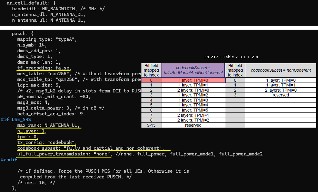
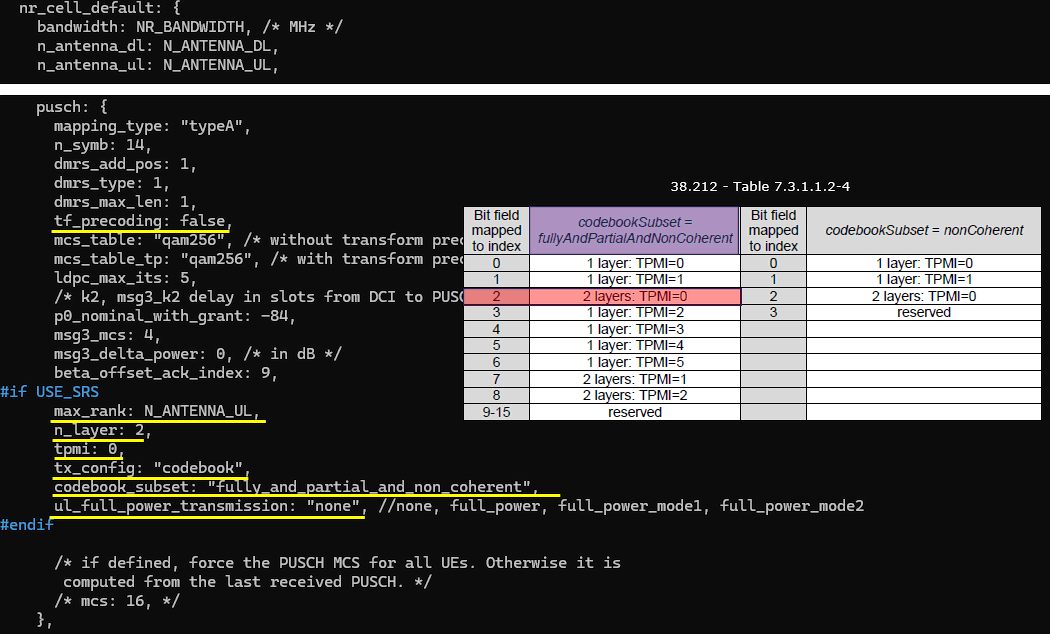
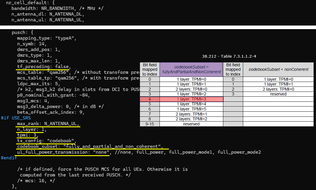
The important part is the SRS and codebook configuration. USE_SRS enables uplink sounding, so the gNB can estimate the UL channel. tx_config: "codebook" means the UE uses a standardized UL precoder, not an arbitrary one. n_layer: 1 configures one-layer PUSCH transmission. tpmi: 2 forces TPMI index 2. With codebook_subset: "fully_and_partial_and_non_coherent", this TPMI is interpreted using the wide UL codebook subset defined by 3GPP. "fully_and_partial_and_non_coherent" determines the column of the 3GPP table. The combination of n_layer and tpmi value determines the row of the table. In this case, n_layer :1 and tpmi:2 corresponds to 'Bit field mapped to index' : 3.
So, in short, this configuration makes the UE transmit one-layer PUSCH using a specific UL codebook precoder selected by TPMI 2. It is useful for checking whether the UE correctly applies the TPMI indicated by the gNB.

This setting is not mandatory either, but I extended the inactivity timer so that the connection can stay active long enough to check PHY throughput without generating IP throughput. inactivity_timer: 60000 keeps the UE in connected state for a long time even when there is no user-plane IP traffic, so the UE does not quickly move back to idle state while I am monitoring the forced UL scheduling and TPMI-related PUSCH behavior. This is useful in this test because I want to observe the PHY-layer uplink throughput and confirm the TPMI operation under a stable connected condition, not measure application-layer throughput generated by ping, iperf, or other IP traffic. By keeping the connection active for a longer time, I can check whether the UE continues to apply the configured UL precoding behavior without continuously generating external traffic.
Perform the Test
After starting the Callbox, first check whether the cell is configured as intended.
The important part in this test is the uplink configuration, so I checked the number of UL antennas and the number of UL layers using the cell phy command, and I also checked the enabled RX channels using the rf_info command. In the cell phy result, the UL ANT value is 2 and the UL NL value is also 2, which means that two uplink antennas and two uplink layers are configured. This confirms that the cell is configured for UL 2x2 MIMO. In the rf_info result, RX0 and RX1 are enabled, which means that two uplink receive paths are active in the Callbox. This matches the intended UL 2x2 MIMO configuration because the gNB needs two RX channels to receive the two uplink antenna paths from the UE. The key confirmation from this step is that the gNB is configured with two UL antennas, two UL layers, and two active RX paths, so the Callbox side is ready for the UL 2x2 MIMO TPMI test.
Power on UE on UE sim. (NOTE : If you are using your own DUT instead of Amarisoft UEsim, you can replace this with your own UE operation).
Confirm that the UE completes the attach and check the throughput. Confirm that the UE completes the attach and check the throughput.
Log Analysis
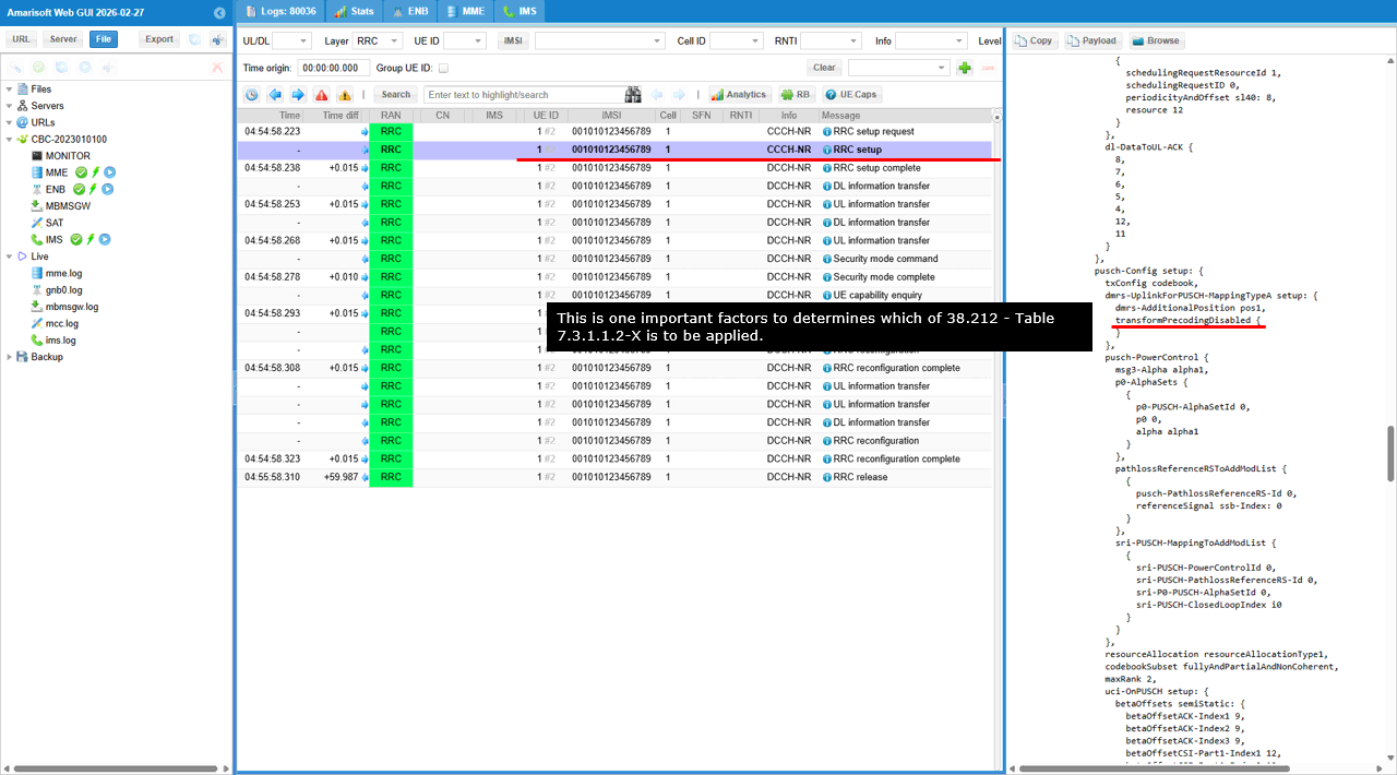
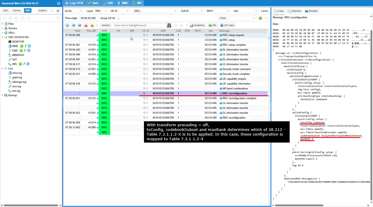
In the RRC setup the UE receives pusch-Config setup. Inside that, txConfig codebook indicates codebook-based UL transmission. Then transformPrecoder disabled confirms that CP-OFDM PUSCH is used, not DFT-s-OFDM.
This is important because the TPMI interpretation depends on this condition. With transform precoding disabled, the UE should apply the UL codebook rule from 38.212 Table 7.3.1.1.2-4.
In short, this log is the RRC-level confirmation that the UE was configured for codebook-based UL MIMO PUSCH, CP-OFDM operation, and TPMI-based precoder selection.
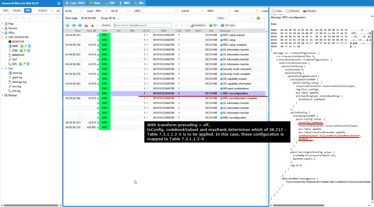
txConfig codebook configures the UE to use codebook-based uplink PUSCH transmission. This means the uplink precoder is not chosen freely by the UE. It is selected from the standardized UL codebook and can be controlled by TPMI in the UL grant.
codebookSubset fullyAndPartialAndNonCoherent tells the UE which group of UL codebook entries is allowed. In this case, the widest subset is enabled. So fully coherent, partially coherent, and non-coherent precoding candidates can be used.
maxRank 2 configures the maximum number of UL PUSCH layers as 2. This does not mean every PUSCH is transmitted with 2 layers. It means the UE may be scheduled with up to 2 layers, depending on the UL grant and the selected TPMI.
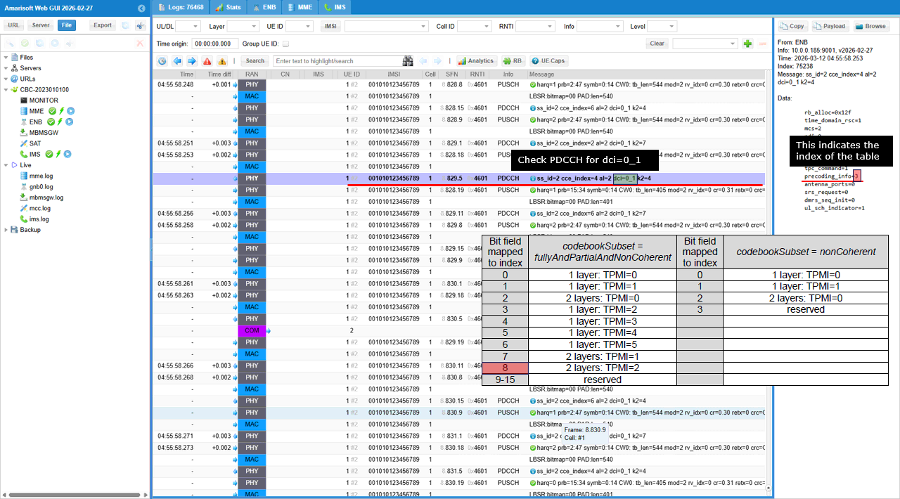
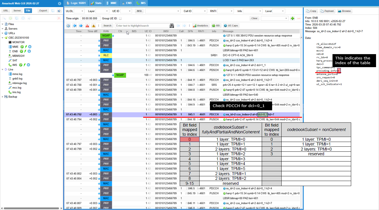
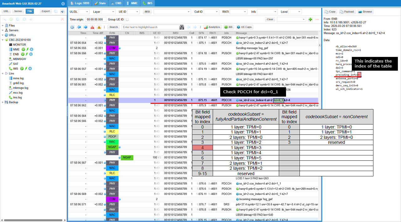
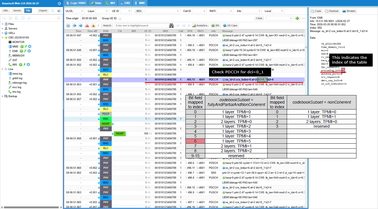
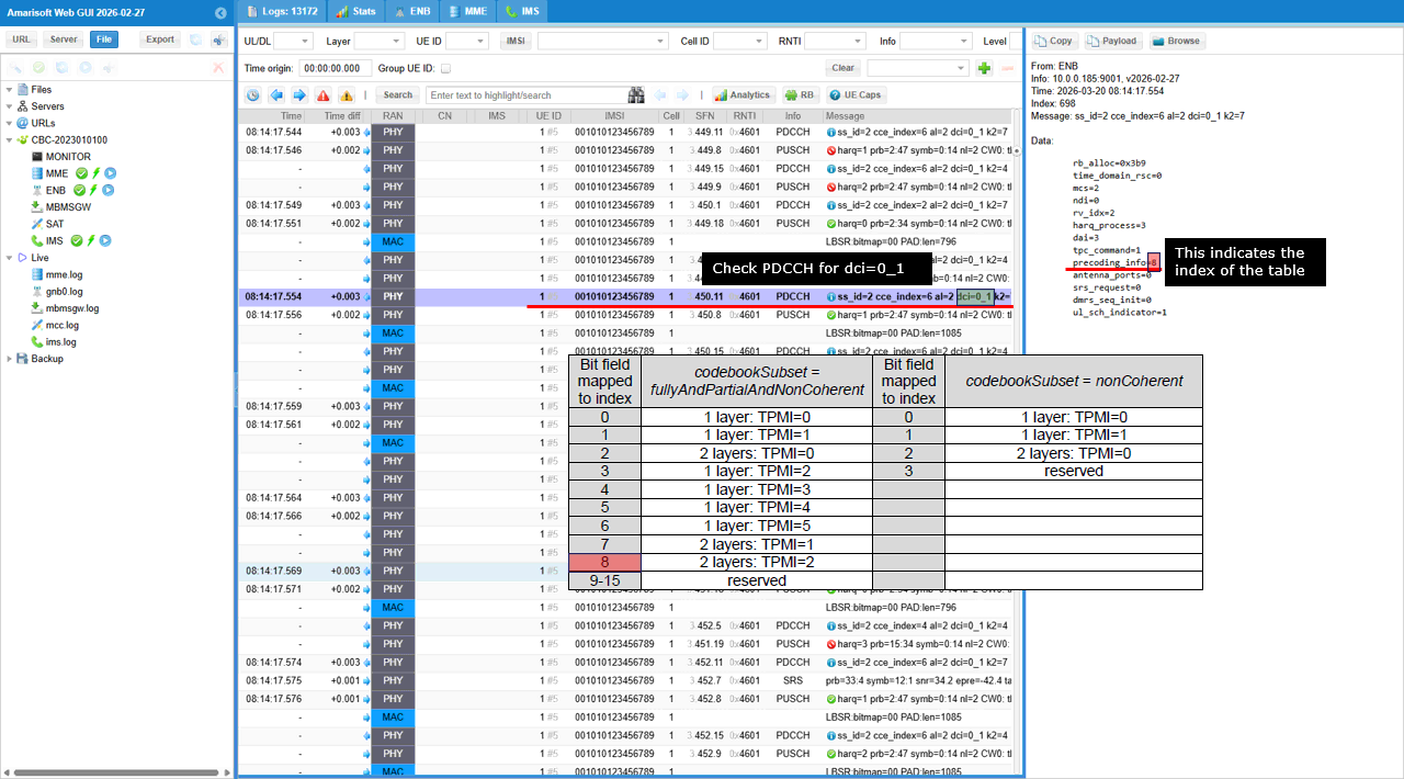
This image shows the actual UL grant decoding on PDCCH.
The highlighted PDCCH message has dci=0_1, so this is an uplink scheduling grant for PUSCH. In the decoded DCI fields, precoding_info=3 is highlighted. This value is the bit-field index used to select the corresponding UL TPMI entry from the 38.212 table. For codebookSubset = fullyAndPartialAndNonCoherent, index 3 maps to 1 layer: TPMI=2.
So this log indicates that the gNB scheduled PUSCH using DCI 0_1, and the UE was instructed to transmit one-layer PUSCH with TPMI 2.
SubTest 1 : Index 0
The main purpose of this sub text is to show how to set the 'Bit field mapped index' to 0 which indicates 1 layer, TPMI 0
The important part is the SRS and codebook configuration. USE_SRS enables uplink sounding, so the gNB can estimate the UL channel. tx_config: "codebook" means the UE uses a standardized UL precoder, not an arbitrary one. n_layer: 1 configures one-layer PUSCH transmission. tpmi: 0 forces TPMI index 0. With codebook_subset: "fully_and_partial_and_non_coherent", this TPMI is interpreted using the wide UL codebook subset defined by 3GPP. "fully_and_partial_and_non_coherent" determines the column of the 3GPP table. The combination of n_layer and tpmi value determines the row of the table. In this case, n_layer :1 and tpmi:2 corresponds to 'Bit field mapped to index' : 0.
So, in short, this configuration makes the UE transmit one-layer PUSCH using a specific UL codebook precoder selected by TPMI 0. It is useful for checking whether the UE correctly applies the TPMI indicated by the gNB.
txConfig codebook configures the UE to use codebook-based uplink PUSCH transmission. This means the uplink precoder is not chosen freely by the UE. It is selected from the standardized UL codebook and can be controlled by TPMI in the UL grant.
codebookSubset fullyAndPartialAndNonCoherent tells the UE which group of UL codebook entries is allowed. In this case, the widest subset is enabled. So fully coherent, partially coherent, and non-coherent precoding candidates can be used.
maxRank 2 configures the maximum number of UL PUSCH layers as 2. This does not mean every PUSCH is transmitted with 2 layers. It means the UE may be scheduled with up to 2 layers, depending on the UL grant and the selected TPMI.
This log shows the actual UL grant decoding on PDCCH.
The highlighted PDCCH message has dci=0_1, so this is an uplink scheduling grant for PUSCH. In the decoded DCI fields, precoding_info=0 is highlighted. This value is the bit-field index used to select the corresponding UL TPMI entry from the 38.212 table. For codebookSubset = fullyAndPartialAndNonCoherent, index 0 maps to 1 layer: TPMI=0.
So this log indicates that the gNB scheduled PUSCH using DCI 0_1, and the UE was instructed to transmit one-layer PUSCH with TPMI 2.
SubTest 2 : Index 2
The main purpose of this sub text is to show how to set the 'Bit field mapped index' to 2 which indicates 2 layer, TPMI 0
The important part is the SRS and codebook configuration. USE_SRS enables uplink sounding, so the gNB can estimate the UL channel. tx_config: "codebook" means the UE uses a standardized UL precoder, not an arbitrary one. n_layer: 2 configures one-layer PUSCH transmission. tpmi: 0 forces TPMI index 0. With codebook_subset: "fully_and_partial_and_non_coherent", this TPMI is interpreted using the wide UL codebook subset defined by 3GPP. "fully_and_partial_and_non_coherent" determines the column of the 3GPP table. The combination of n_layer and tpmi value determines the row of the table. In this case, n_layer :2 and tpmi:0 corresponds to 'Bit field mapped to index' : 2.
So, in short, this configuration makes the UE transmit one-layer PUSCH using a specific UL codebook precoder selected by TPMI 0. It is useful for checking whether the UE correctly applies the TPMI indicated by the gNB.
txConfig codebook configures the UE to use codebook-based uplink PUSCH transmission. This means the uplink precoder is not chosen freely by the UE. It is selected from the standardized UL codebook and can be controlled by TPMI in the UL grant.
codebookSubset fullyAndPartialAndNonCoherent tells the UE which group of UL codebook entries is allowed. In this case, the widest subset is enabled. So fully coherent, partially coherent, and non-coherent precoding candidates can be used.
maxRank 2 configures the maximum number of UL PUSCH layers as 2. This does not mean every PUSCH is transmitted with 2 layers. It means the UE may be scheduled with up to 2 layers, depending on the UL grant and the selected TPMI.

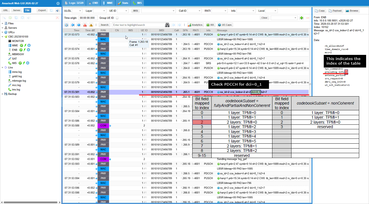
This log shows the actual UL grant decoding on PDCCH.
The highlighted PDCCH message has dci=0_1, so this is an uplink scheduling grant for PUSCH. In the decoded DCI fields, precoding_info=2 is highlighted. This value is the bit-field index used to select the corresponding UL TPMI entry from the 38.212 table. For codebookSubset = fullyAndPartialAndNonCoherent, index 2 maps to 2 layer: TPMI=0.
So this log indicates that the gNB scheduled PUSCH using DCI 0_1, and the UE was instructed to transmit two-layer PUSCH with TPMI 0.
SubTest 3 : Index 4
The main purpose of this sub text is to show how to set the 'Bit field mapped index' to 4 which indicates 1 layer, TPMI 3
The important part is the SRS and codebook configuration. USE_SRS enables uplink sounding, so the gNB can estimate the UL channel. tx_config: "codebook" means the UE uses a standardized UL precoder, not an arbitrary one. n_layer: 1 configures one-layer PUSCH transmission. tpmi: 3 forces TPMI index 0. With codebook_subset: "fully_and_partial_and_non_coherent", this TPMI is interpreted using the wide UL codebook subset defined by 3GPP. "fully_and_partial_and_non_coherent" determines the column of the 3GPP table. The combination of n_layer and tpmi value determines the row of the table. In this case, n_layer :1 and tpmi:3 corresponds to 'Bit field mapped to index' : 4
So, in short, this configuration makes the UE transmit one-layer PUSCH using a specific UL codebook precoder selected by TPMI 3. It is useful for checking whether the UE correctly applies the TPMI indicated by the gNB.
txConfig codebook configures the UE to use codebook-based uplink PUSCH transmission. This means the uplink precoder is not chosen freely by the UE. It is selected from the standardized UL codebook and can be controlled by TPMI in the UL grant.
codebookSubset fullyAndPartialAndNonCoherent tells the UE which group of UL codebook entries is allowed. In this case, the widest subset is enabled. So fully coherent, partially coherent, and non-coherent precoding candidates can be used.
maxRank 2 configures the maximum number of UL PUSCH layers as 2. This does not mean every PUSCH is transmitted with 2 layers. It means the UE may be scheduled with up to 2 layers, depending on the UL grant and the selected TPMI.
This log shows the actual UL grant decoding on PDCCH.
The highlighted PDCCH message has dci=0_1, so this is an uplink scheduling grant for PUSCH. In the decoded DCI fields, precoding_info=4 is highlighted. This value is the bit-field index used to select the corresponding UL TPMI entry from the 38.212 table. For codebookSubset = fullyAndPartialAndNonCoherent, index 4 maps to 1 layer: TPMI=3.
So this log indicates that the gNB scheduled PUSCH using DCI 0_1, and the UE was instructed to transmit one-layer PUSCH with TPMI 3.
SubTest 4 : Index 6
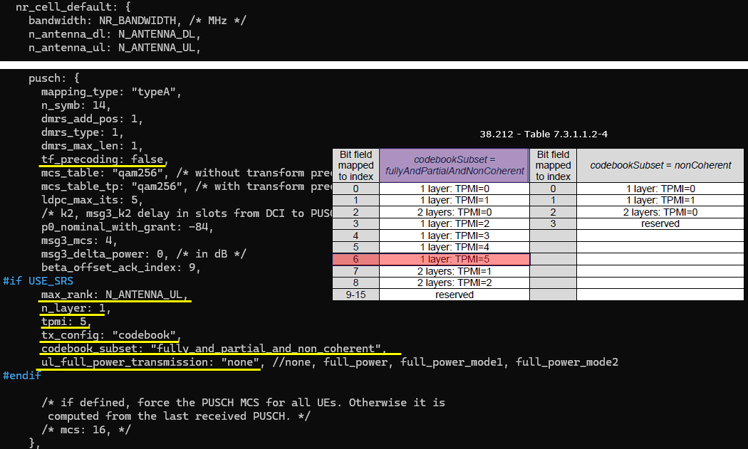
The main purpose of this sub text is to show how to set the 'Bit field mapped index' to 4 which indicates 1 layer, TPMI 5
The important part is the SRS and codebook configuration. USE_SRS enables uplink sounding, so the gNB can estimate the UL channel. tx_config: "codebook" means the UE uses a standardized UL precoder, not an arbitrary one. n_layer: 1 configures one-layer PUSCH transmission. tpmi: 5 forces TPMI index 5. With codebook_subset: "fully_and_partial_and_non_coherent", this TPMI is interpreted using the wide UL codebook subset defined by 3GPP. "fully_and_partial_and_non_coherent" determines the column of the 3GPP table. The combination of n_layer and tpmi value determines the row of the table. In this case, n_layer :1 and tpmi:5 corresponds to 'Bit field mapped to index' : 6
So, in short, this configuration makes the UE transmit one-layer PUSCH using a specific UL codebook precoder selected by TPMI 5. It is useful for checking whether the UE correctly applies the TPMI indicated by the gNB.
txConfig codebook configures the UE to use codebook-based uplink PUSCH transmission. This means the uplink precoder is not chosen freely by the UE. It is selected from the standardized UL codebook and can be controlled by TPMI in the UL grant.
codebookSubset fullyAndPartialAndNonCoherent tells the UE which group of UL codebook entries is allowed. In this case, the widest subset is enabled. So fully coherent, partially coherent, and non-coherent precoding candidates can be used.
maxRank 2 configures the maximum number of UL PUSCH layers as 2. This does not mean every PUSCH is transmitted with 2 layers. It means the UE may be scheduled with up to 2 layers, depending on the UL grant and the selected TPMI.
This log shows the actual UL grant decoding on PDCCH.
The highlighted PDCCH message has dci=0_1, so this is an uplink scheduling grant for PUSCH. In the decoded DCI fields, precoding_info=6 is highlighted. This value is the bit-field index used to select the corresponding UL TPMI entry from the 38.212 table. For codebookSubset = fullyAndPartialAndNonCoherent, index 6 maps to 1 layer: TPMI=5.
So this log indicates that the gNB scheduled PUSCH using DCI 0_1, and the UE was instructed to transmit one-layer PUSCH with TPMI 5.
SubTest 5 : Index 8
The main purpose of this sub text is to show how to set the 'Bit field mapped index' to 4 which indicates 2 layer, TPMI 2
The important part is the SRS and codebook configuration. USE_SRS enables uplink sounding, so the gNB can estimate the UL channel. tx_config: "codebook" means the UE uses a standardized UL precoder, not an arbitrary one. n_layer: 2 configures one-layer PUSCH transmission. tpmi: 2 forces TPMI index 2. With codebook_subset: "fully_and_partial_and_non_coherent", this TPMI is interpreted using the wide UL codebook subset defined by 3GPP. "fully_and_partial_and_non_coherent" determines the column of the 3GPP table. The combination of n_layer and tpmi value determines the row of the table. In this case, n_layer :2 and tpmi:2 corresponds to 'Bit field mapped to index' : 8
So, in short, this configuration makes the UE transmit one-layer PUSCH using a specific UL codebook precoder selected by TPMI 2. It is useful for checking whether the UE correctly applies the TPMI indicated by the gNB.
txConfig codebook configures the UE to use codebook-based uplink PUSCH transmission. This means the uplink precoder is not chosen freely by the UE. It is selected from the standardized UL codebook and can be controlled by TPMI in the UL grant.
codebookSubset fullyAndPartialAndNonCoherent tells the UE which group of UL codebook entries is allowed. In this case, the widest subset is enabled. So fully coherent, partially coherent, and non-coherent precoding candidates can be used.
maxRank 2 configures the maximum number of UL PUSCH layers as 2. This does not mean every PUSCH is transmitted with 2 layers. It means the UE may be scheduled with up to 2 layers, depending on the UL grant and the selected TPMI.
This log shows the actual UL grant decoding on PDCCH.
The highlighted PDCCH message has dci=0_1, so this is an uplink scheduling grant for PUSCH. In the decoded DCI fields, precoding_info=8 is highlighted. This value is the bit-field index used to select the corresponding UL TPMI entry from the 38.212 table. For codebookSubset = fullyAndPartialAndNonCoherent, index 8 maps to 2 layer: TPMI=2.
So this log indicates that the gNB scheduled PUSCH using DCI 0_1, and the UE was instructed to transmit two-layer PUSCH with TPMI 2.
RRC / NAS Signaling
RrcSetup (SA)
: This is the RrcSetup message sent by gNB to configure NR SA. (
{
message c1: rrcSetup: {
rrc-TransactionIdentifier 0,
criticalExtensions rrcSetup: {
radioBearerConfig {
...
},
masterCellGroup {
cellGroupId 0,
rlc-BearerToAddModList {
...
},
mac-CellGroupConfig {
...
},
physicalCellGroupConfig {
pdsch-HARQ-ACK-Codebook dynamic
},
spCellConfig {
spCellConfigDedicated {
initialDownlinkBWP {
pdcch-Config setup: {
...
},
pdsch-Config setup: {
...
}
},
firstActiveDownlinkBWP-Id 0,
uplinkConfig {
initialUplinkBWP {
pucch-Config setup: {
...
},
pusch-Config setup: {
txConfig codebook,
dmrs-UplinkForPUSCH-MappingTypeA setup: {
dmrs-AdditionalPosition pos1,
transformPrecodingDisabled {
}
},
pusch-PowerControl {
...
},
resourceAllocation resourceAllocationType1,
codebookSubset nonCoherent,
maxRank 4,
uci-OnPUSCH setup: {
...
}
},
srs-Config setup: {
...
},
firstActiveUplinkBWP-Id 0,
pusch-ServingCellConfig setup: {
}
},
pdcch-ServingCellConfig setup: {
},
pdsch-ServingCellConfig setup: {
...
},
csi-MeasConfig setup: {
...
},
tag-Id 0
}