NR SA SearchSpace0
The purpose of this tutorial is to see how SearchSpace0 is configured and verified. In terms of test configuration and test procedure, it is very simple. Just configure a few configuration settings in enb.cfg and run the test. you don't even need to connect any UE. All you need to do for verification is to enable lower layer logging and MIB/BCCH.
It is assumed that you already have basic understandings on what is the SearchSpace 0 (If you are not familiar with the concept of the coreset itself, I would suggest to check out this note). SearchSpace0 is the search space where DCI for SIB1 PDSCH is allocated.
- i) define various predefined set of configuration in 3GPP specification (both gNB and UE should have these predefined table in it)
- ii) Inform the UE on which table and which index of the table to use via MIB (PBCH)
The summary of this mechanism would be illustrated as below (as per my understanding).

Image Source : SIB1 decoding Procedure in Sharetechnote
In 3GPP, SSB SCS,PDCCH SCS, Min BW determines which table to apply and the MIB parameter determines the index of the selected table. In Amarisoft gNB, SSB SCS,PDCCH SCS, Min BW determines which table to apply and the index of the table is specified in enb.cfg. (The index specified in the configuration file is populated in MIB).
Table of Contents
- NR SA SearchSpace0
- Introduction
- Summary of the Tutorial
- Key Configuration Parameter
- Test 1 : SSB index 0 or 1, SearchSpace 0 = {0,..,15}
- Sub Test 1 : SSB index 0, SearchSpace0 = 0
- Sub Test 2 : SSB index 0, SearchSpace0 = 1
- Sub Test 3 : SSB index 0, SearchSpace0 = 2
- Sub Test 4 : SSB index 0, SearchSpace0 = 3
- Sub Test 5 : SSB index 0, SearchSpace0 = 4
- Sub Test 6 : SSB index 0, SearchSpace0 = 5
- Sub Test 7 : SSB index 0, SearchSpace0 = 6
- Sub Test 8 : SSB index 0, SearchSpace0 = 7
- Sub Test 9 : SSB index 0, SearchSpace0 = 8
- Sub Test 10 : SSB index 0, SearchSpace0 = 9
- Sub Test 11 : SSB index 0, SearchSpace0 = 10
- Sub Test 12 : SSB index 1, SearchSpace0 = 11
- Sub Test 13 : SSB index 0, SearchSpace0 = 12
- Sub Test 14 : SSB index 1, SearchSpace0 = 13
- Sub Test 15 : SSB index 0, SearchSpace0 = 14
- Sub Test 16 : SSB index 1, SearchSpace0 = 15
- RRC / NAS Signaling
Introduction
In the context of 5G NR (New Radio) networks, SearchSpace0 is a fundamental concept within the initial access and system information acquisition procedures. It is specifically associated with the configuration and allocation of Downlink Control Information (DCI) for the Physical Downlink Shared Channel (PDSCH) carrying System Information Block Type 1 (SIB1). SearchSpace0 operates within a predefined set of configurations as specified by 3GPP standards, involving intricate relationships between the Synchronization Signal Block (SSB) subcarrier spacing (SCS), PDCCH SCS, and the minimum bandwidth supported by the cell. These parameters collectively determine which configuration table is employed for SearchSpace0, with the specific index within that table being conveyed to the User Equipment (UE) via the Master Information Block (MIB) broadcasted over the Physical Broadcast Channel (PBCH). In practical implementations such as Amarisoft gNB, these settings are managed through configuration files (e.g., enb.cfg), allowing for flexible adaptation and verification of SearchSpace0 behavior without the need for active UE connections. The configuration and validation of SearchSpace0 are crucial for ensuring reliable delivery of essential system information to UEs during the cell search and initial access phase, ultimately facilitating seamless network entry and service availability. Understanding these architectural underpinnings and control signaling mechanisms is vital for engineers and researchers working with 5G NR RAN (Radio Access Network) infrastructure, as it directly impacts network accessibility, interoperability, and compliance with 3GPP specifications.
-
Context and Background
- SearchSpace0 is a core mechanism for mapping control information required for initial UE access and SIB1 delivery in 5G NR networks.
- It is tightly coupled with CORESET0 (Control Resource Set 0), which defines where and how control channels such as PDCCH are scheduled for initial system information transmission.
- 3GPP specifications provide predefined configuration tables referenced by both gNB (5G base station) and UE to ensure interoperability and standardized behavior.
- The relevant configuration parameters—SSB SCS, PDCCH SCS, and minimum bandwidth—are foundational to selecting the appropriate SearchSpace0 table and index.
-
Relevance and Importance of the Tutorial
- This tutorial is designed to guide practitioners through the process of SearchSpace0 configuration and verification using a practical, implementation-focused approach.
- Proper configuration of SearchSpace0 is essential for ensuring UEs can reliably decode SIB1 and access the network, impacting user experience and network performance.
- Understanding the linkage between configuration files (such as enb.cfg), broadcast signaling (MIB/BCCH), and the underlying 3GPP mechanisms is critical for network engineers and system integrators.
-
Learning Outcomes
- Gain a comprehensive understanding of how SearchSpace0 is defined, configured, and signaled in a commercial 5G NR gNB implementation.
- Acquire hands-on skills in setting up and verifying SearchSpace0 using configuration files and logging tools, even without connecting a UE.
- Develop the ability to interpret MIB and BCCH outputs to confirm correct SearchSpace0 operation and compliance with standards.
- Build foundational knowledge that supports further exploration of 5G NR access procedures, control signaling, and system information delivery.
-
Prerequisite Knowledge and Skills
- Basic understanding of 5G NR architecture, including the roles of gNB, UE, and core network components.
- Familiarity with 3GPP specifications relevant to NR control channels, system information, and initial access procedures.
- Experience with network configuration files (e.g., enb.cfg) and the use of protocol logging/monitoring tools.
- General knowledge of how broadcast channels (MIB/BCCH) function in cellular networks.
Summary of the Tutorial
This tutorial demonstrates a comprehensive set of test procedures for verifying the allocation and configuration of Search Space 0 (SearchSpace0) in an NR (5G) gNB setup, specifically focusing on how different search_space0_index values (0 to 15) and SSB (Synchronization Signal Block) indices impact the time domain position of SearchSpace0, as per TS 38.213 - Table 13-11. The procedures are designed for FR1 and CORESET0 Multiplexing Pattern 1, and the tests use a TDD cell with a 40 MHz channel bandwidth.
-
Key Configuration Parameters:
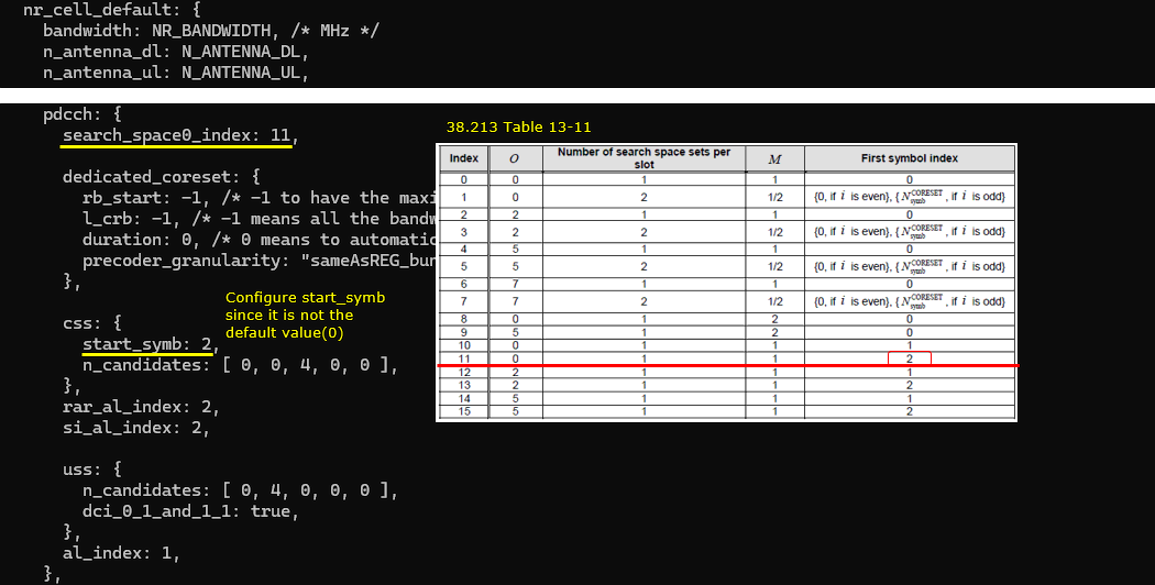
- search_space0_index
- css
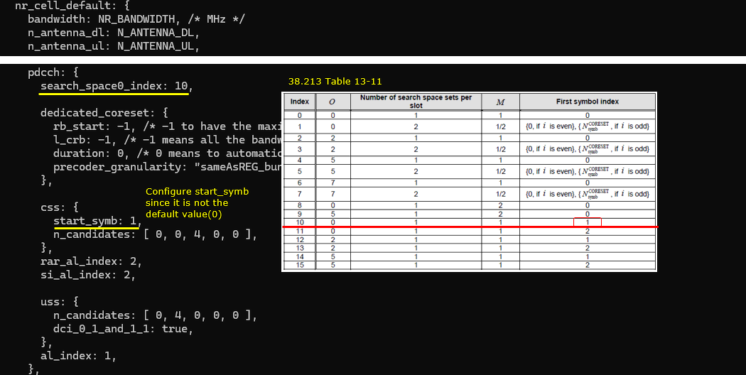
- start_symb
Usually, only search_space0_index needs to be set, but start_symb may also need to be configured, depending on requirements.
-
General Test Procedure for Each Sub Test (applies to Sub Tests 1 through 16):
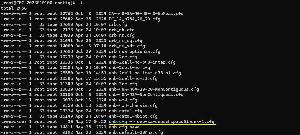
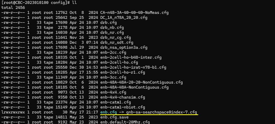
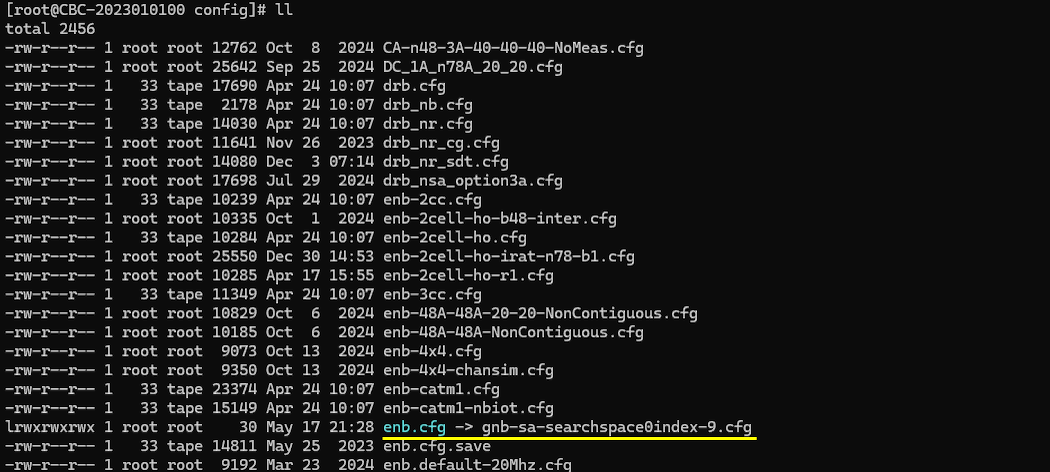
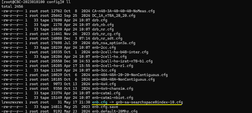
- Select or create the appropriate gNB configuration file (e.g., gnb-sa-searchspace0index-X.cfg, where X is the desired search_space0_index).
- Set the cell to TDD mode (NR_TDD = 1), and assign the channel bandwidth (e.g., NR_BANDWIDTH = 40 MHz).
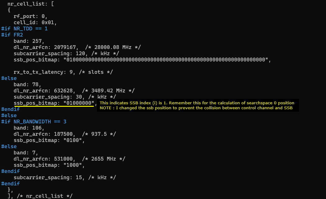
- Configure the SSB bitmap to select the corresponding SSB index (e.g., "10000000" for SSB index 0, "01000000" for SSB index 1).
- Assign the search_space0_index parameter as required by the sub test (from 0 to 15).
- Optionally, set start_symb in the css configuration; default is 0 if not specified.
- Start the LTE service (using Amarisoft Callbox or equivalent platform) and observe the cell PHY results to confirm that the intended configuration is applied.
- No UE connection is necessary for these tests; the focus is on cell configuration and broadcast signaling.
- For result verification, collect and analyze MIB, BCCH, and PHY layer logs:
- Inspect the MIB message to ensure SearchSpaceZero is set as intended.
- Use the WebGUI to check the resource block (RB) map; although CORESET0 and SearchSpace0 allocations are not directly visualized, their time domain positions can be inferred based on the SIB1 PDSCH location (as all three reside in the same slot).
- Repeat the above steps for each value of search_space0_index and SSB index as specified by the sub test.
-
Sub Test Specifics:
Each sub test varies the search_space0_index and, in some cases, the SSB index, to demonstrate how SearchSpace0 slot allocation changes. The SSB bitmap is adjusted accordingly. The analysis procedure remains consistent across tests.
-
Log Analysis Methodology:
- Utilize MIB and BCCH logs to verify SearchSpace0 configuration.
- Leverage the WebGUI's RB map to deduce the slot allocation of SearchSpace0 via the SIB1 PDSCH location.
- If necessary, check additional PHY layer logs for confirmation of CORESET0 and SearchSpace0 placement.
-
Additional Notes:
- For some SSB indices (e.g., SSB index 1), the SSB bitmap pattern is adjusted to avoid conflicts with control channel timing.
- All tests reference TS 38.213 for determining SearchSpace0 allocation logic.
Overall, the test suite systematically covers all combinations of SSB indices (0 and 1) with SearchSpace0 indices (0 to 15), ensuring a thorough validation of SearchSpace0 time domain positioning and configuration using the Amarisoft platform and standardized 5G NR configuration methodologies.
Key Configuration Parameter
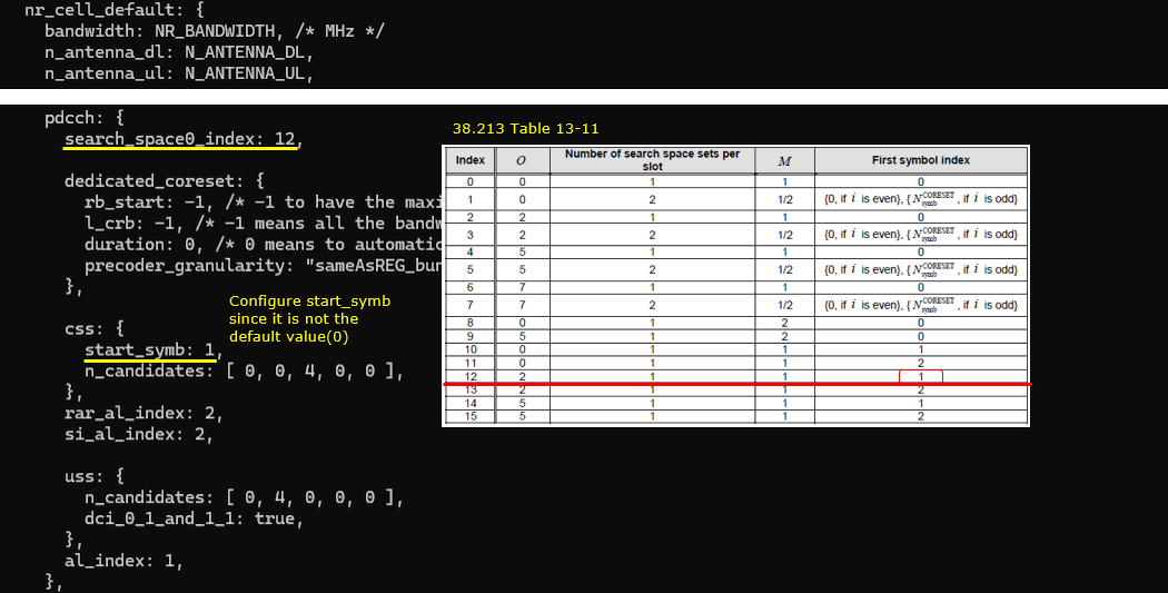
The list of configuration parameters for SearchSpace0 is very short as follows. In many cases, you may need to set search_space0_index only but you may need to set start_symb depending on situations.
Test 1 : SSB index 0 or 1, SearchSpace 0 = {0,..,15}
Sub Test 1 : SSB index 0, SearchSpace0 = 0
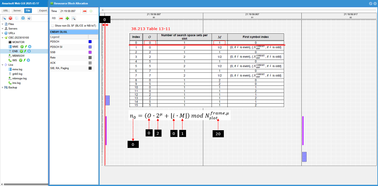
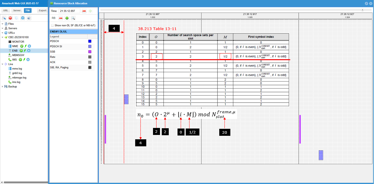
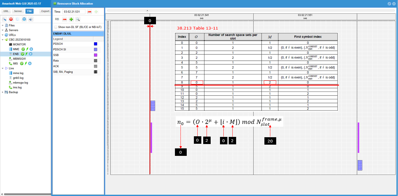
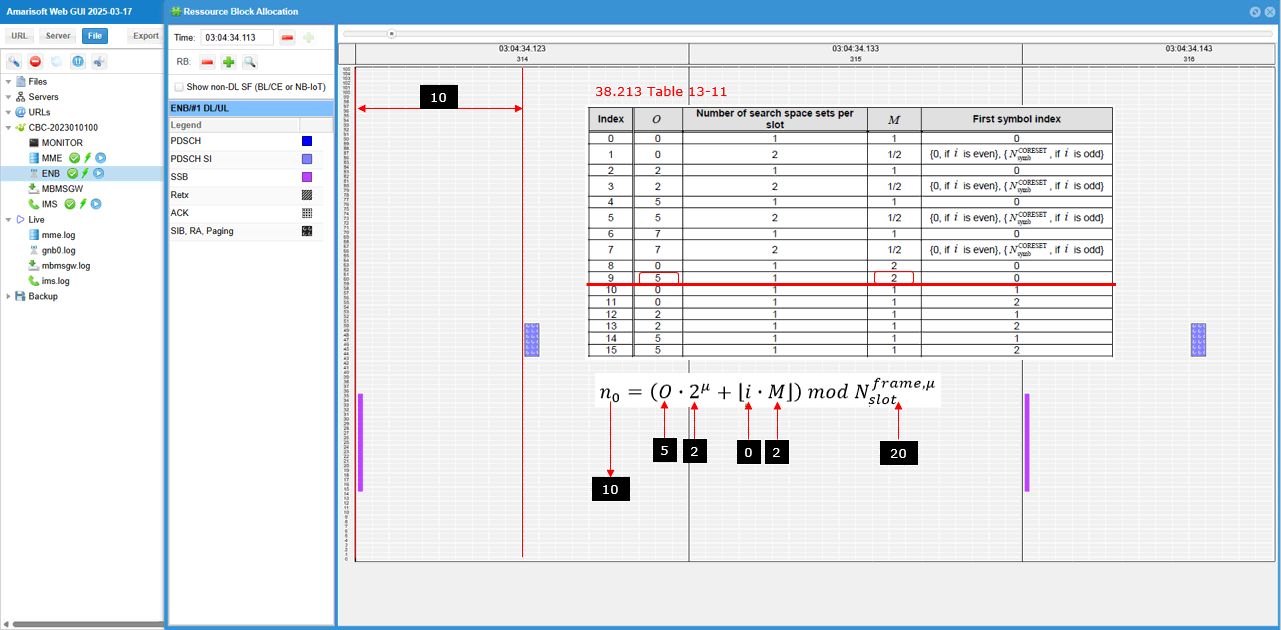
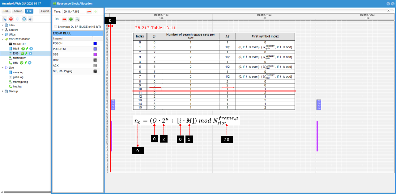
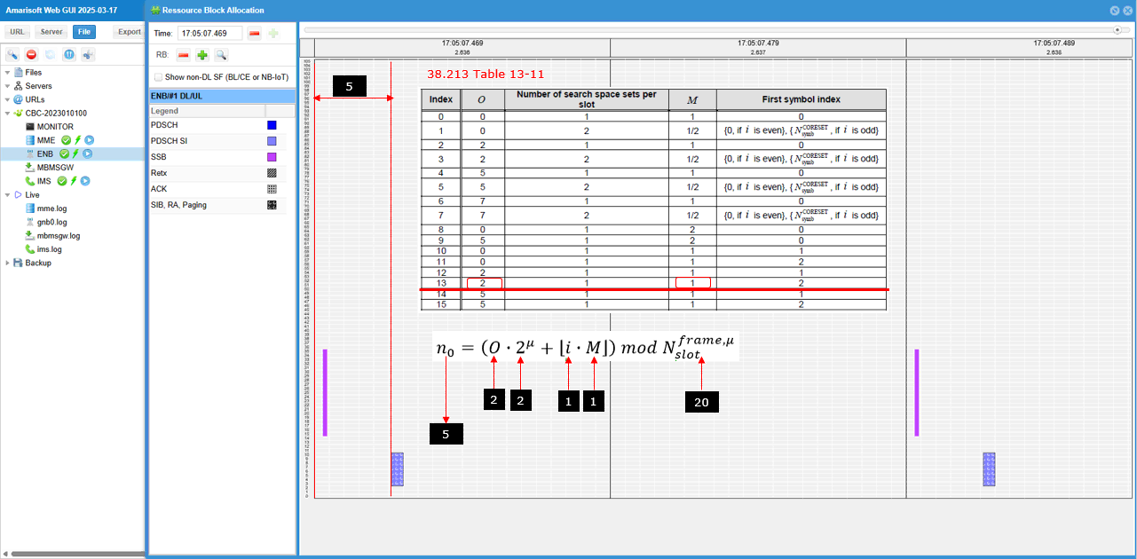
In this sub test, it will be shown where (in which slot) Search Space 0 is allocated for FR1 and Coreset0 Multiplexing Pattern 1. In this case, the search space 0 is allocated based on TS 38.213 - Table 13-11
Configuration
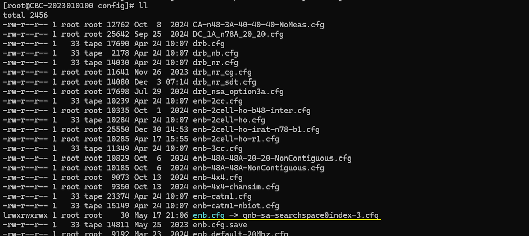
gnb-sa-searchspace0index-0.cfg is used for gNB configuration.
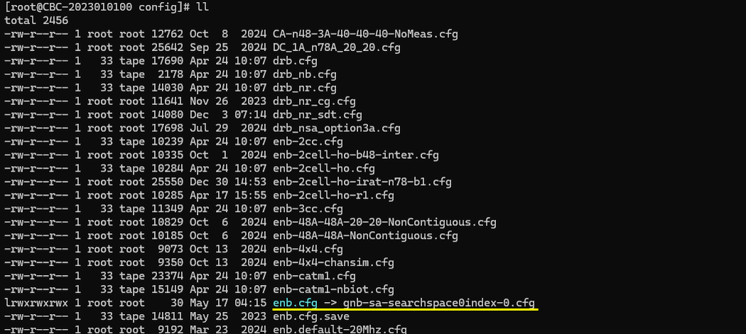
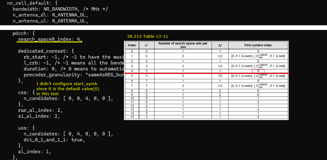
In gnb-sa-searchspace0index-0.cfg , gNB setting is configured as follows.
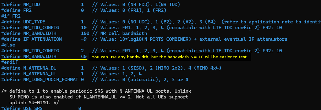
In this case, the cell is set to TDD (NR_TDD = 1) and the channel bandwidth (NR_BANDWIDTH) is set to 40 Mhz. You can set it to any bandwidth as long as it is valid for the specified band (You may refer to 38.101-1 regarding the valid channel bandwidth for a specific band)
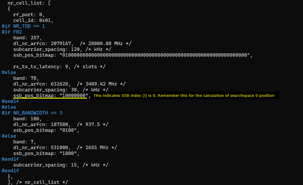
I set "10000000" for SSB bitmap which indicates that the configured SSB index (i) is 0. Remember this index since it is one of the parameter to determine the time domain position of searchspace 0 according to TS 38.213
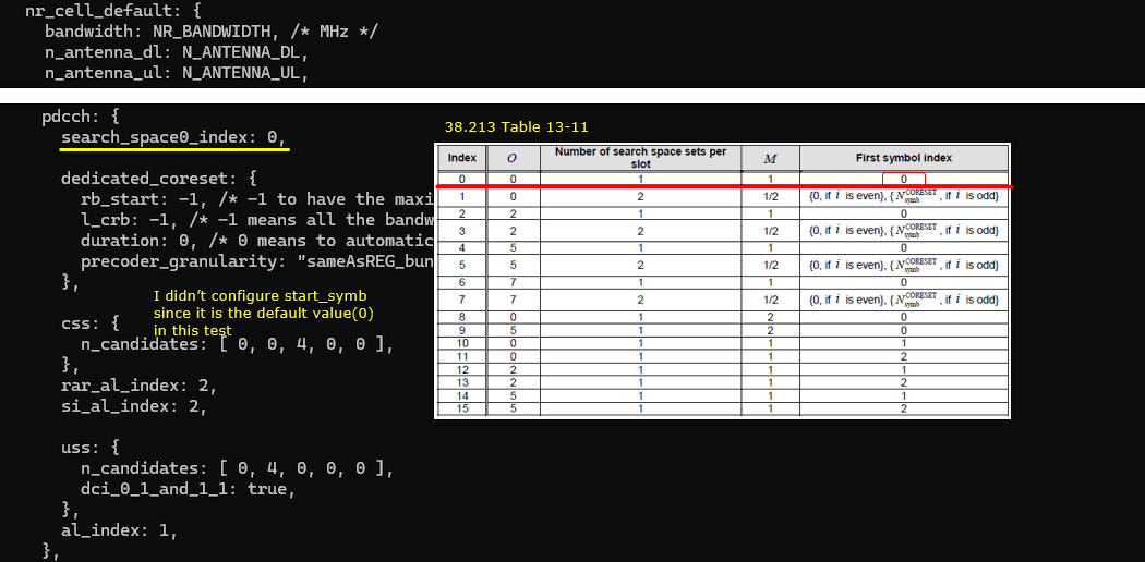
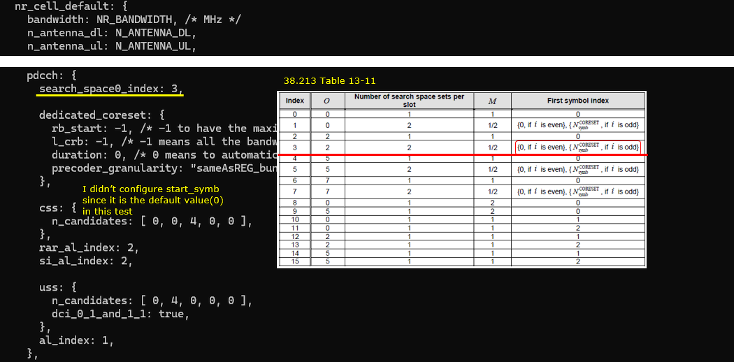
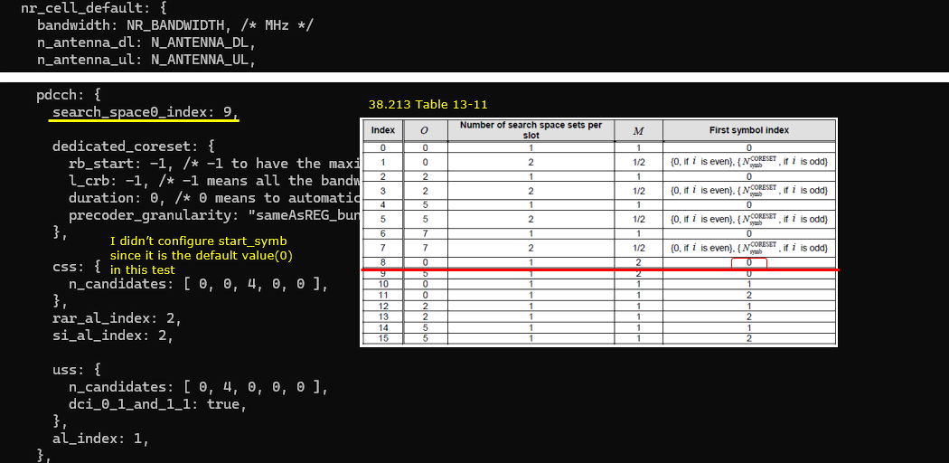
The search space0 is set to the index 0 of 38.213 Table 13-11 (search_space0_index = 0). In this case, the first symbol index (start_symb) is not configured since it is 0 (the default value of start_symb). You can explicitely set start_symb : 0 in css if you like.
Perform the Test
Start the lte service and check out the result of cell phy and see if the configuration is properly set as intended.

This is all you need to do for the test. You don't need to connect any UE for the test.
Log Analysis
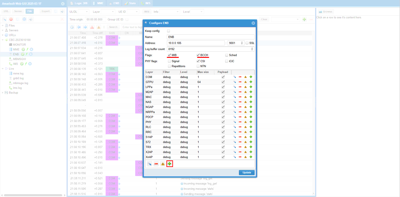
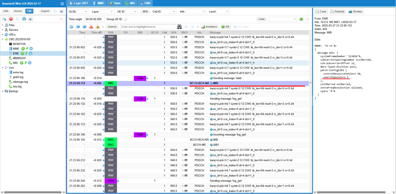
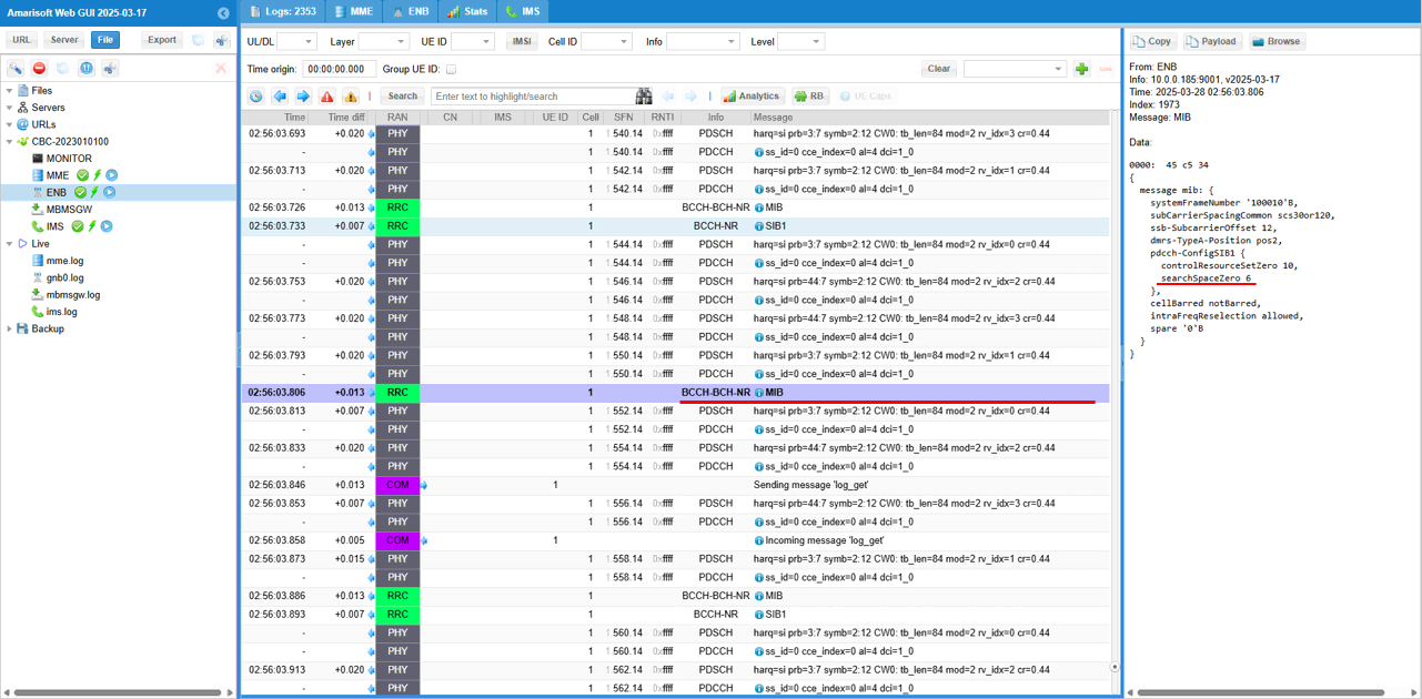
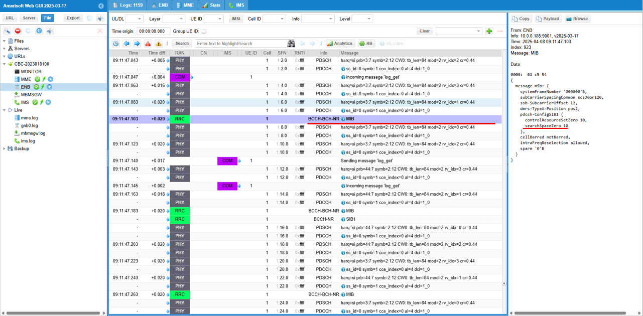
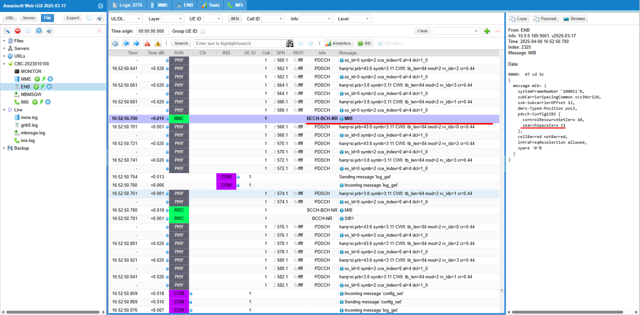
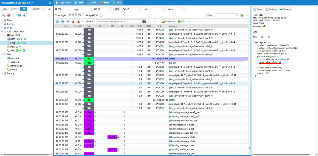
For this test, it is important to collect MIB and BCCH and PHY layer log. A simple way to do it is to check MIB, BCCH and click [+] button in ENB configuration on WebGUI.
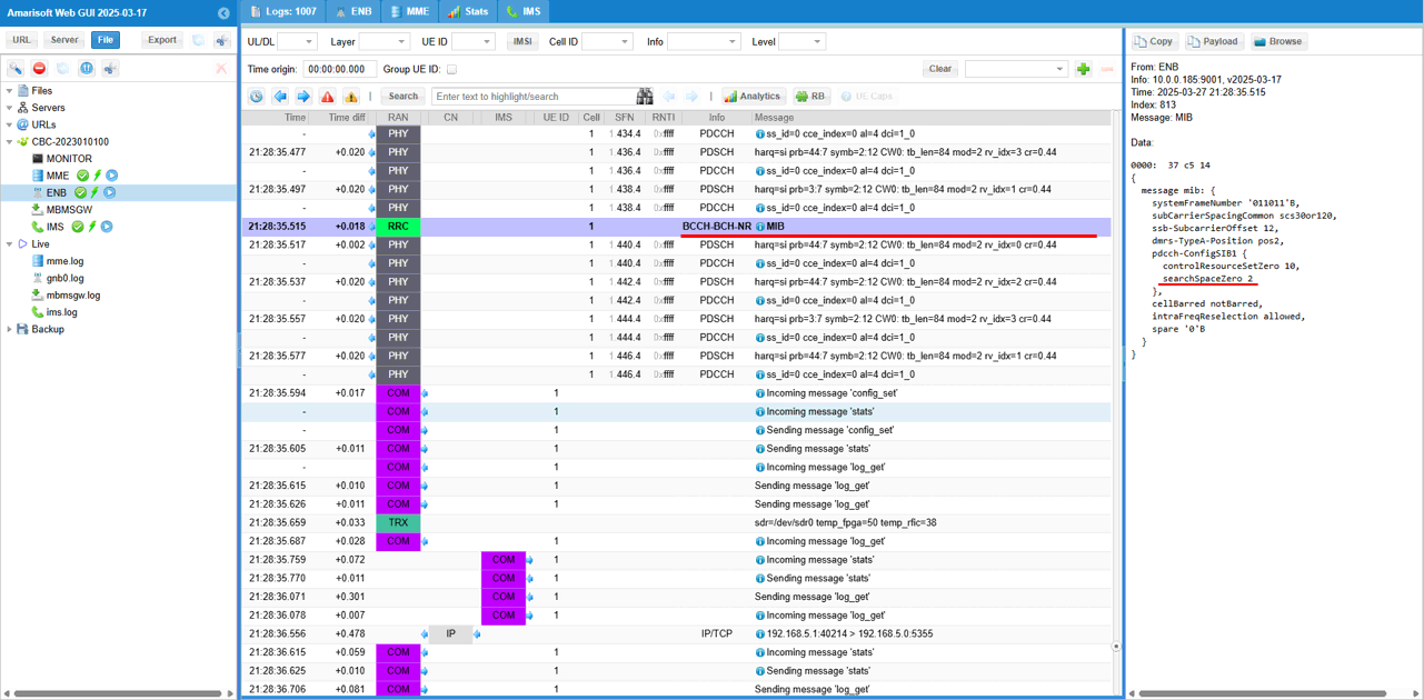
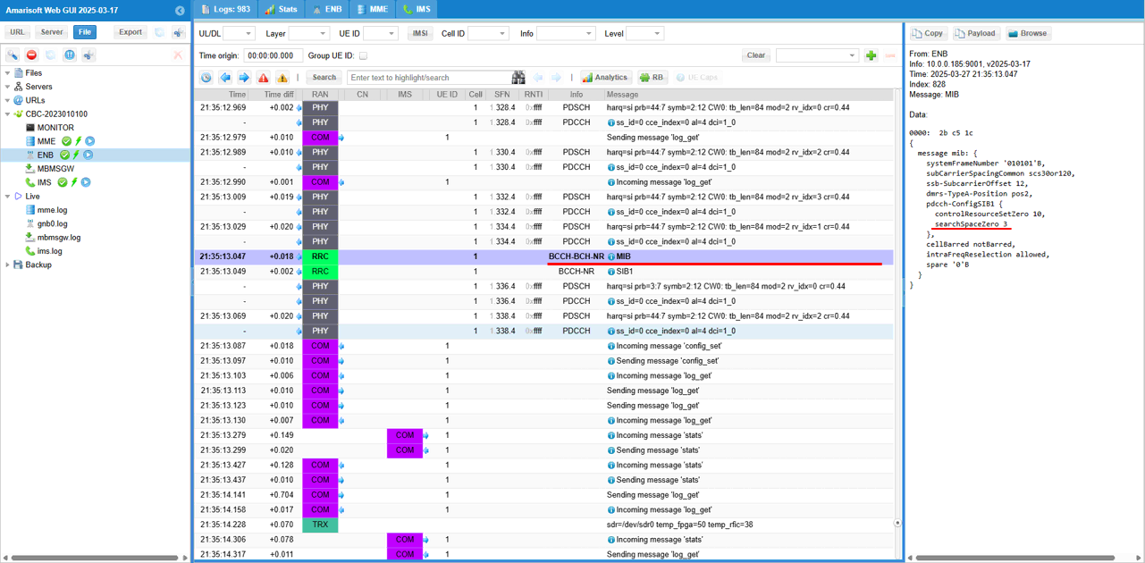
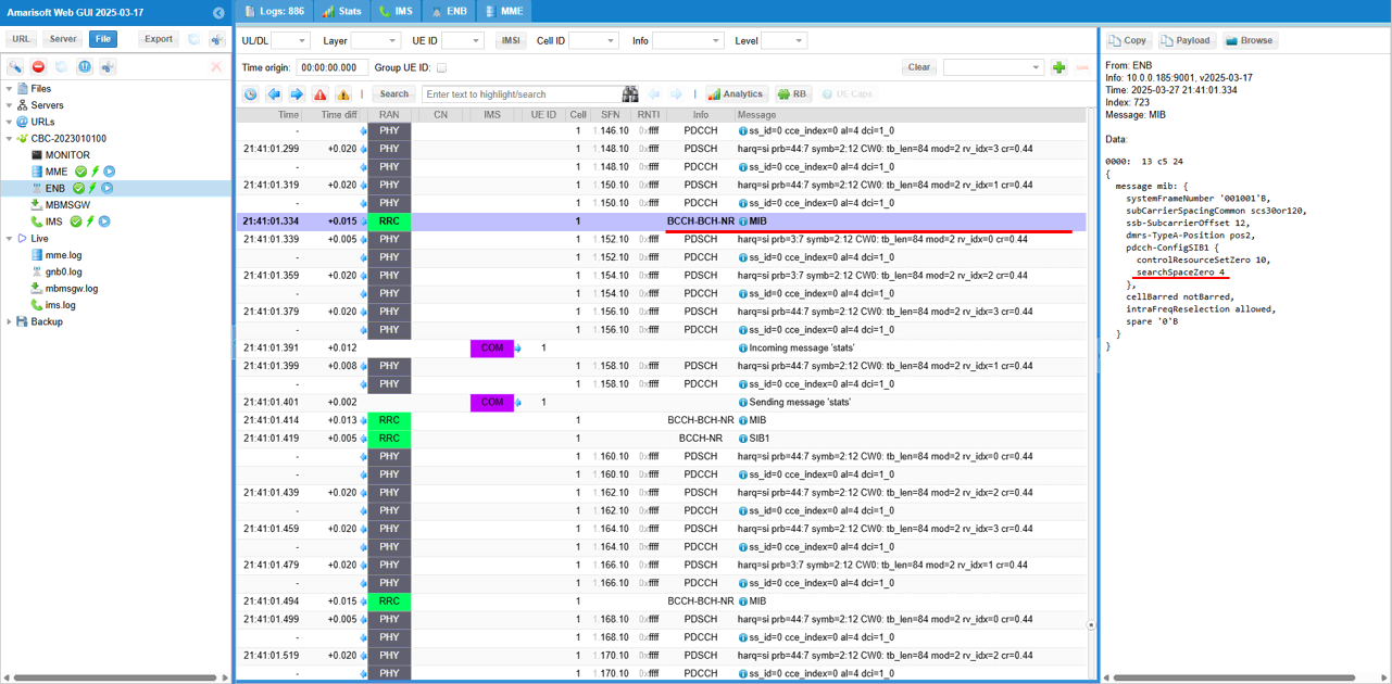
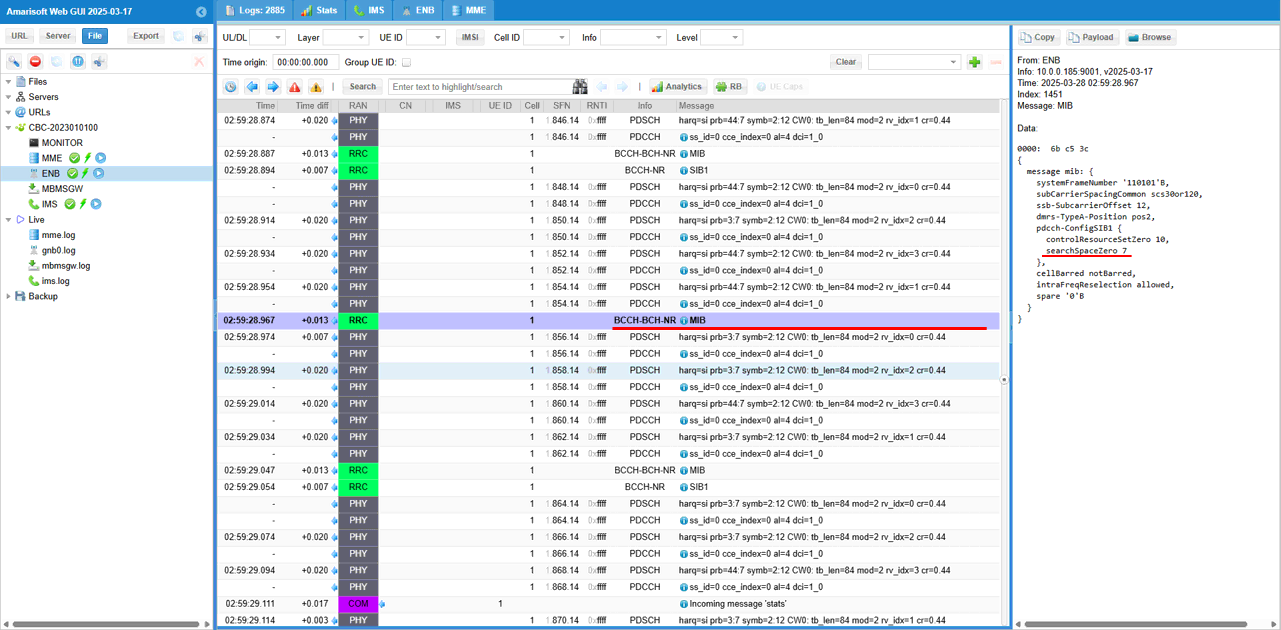
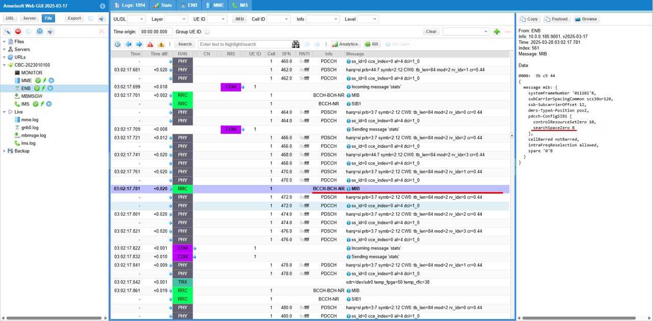
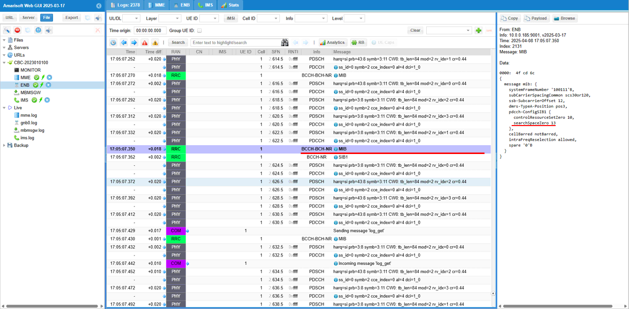
First check out the confents of MIB message and make it sure searchSpaceZero is configured as intended.
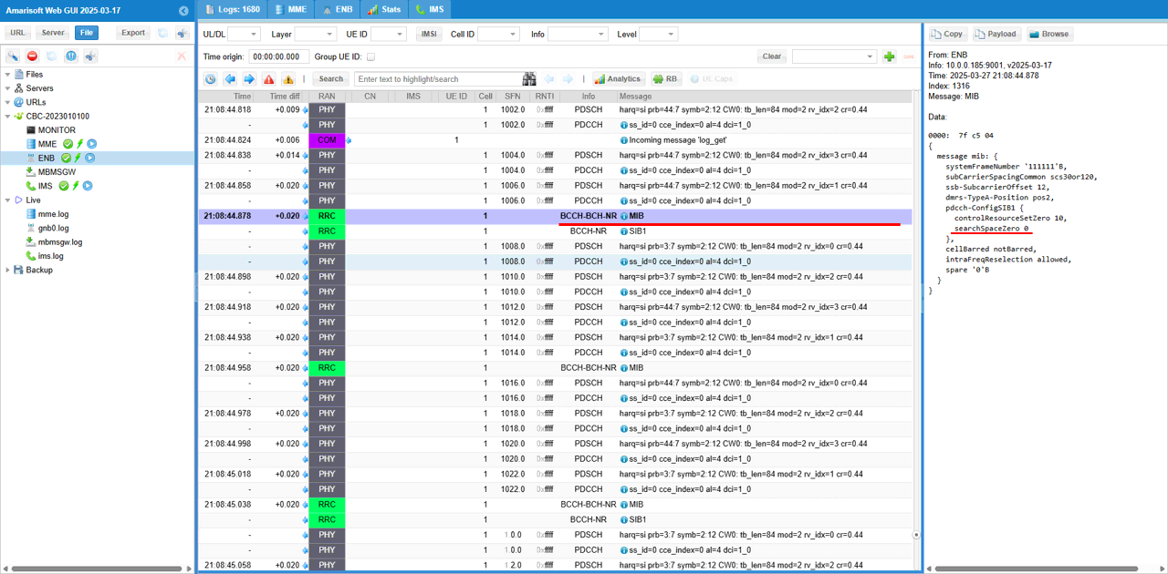
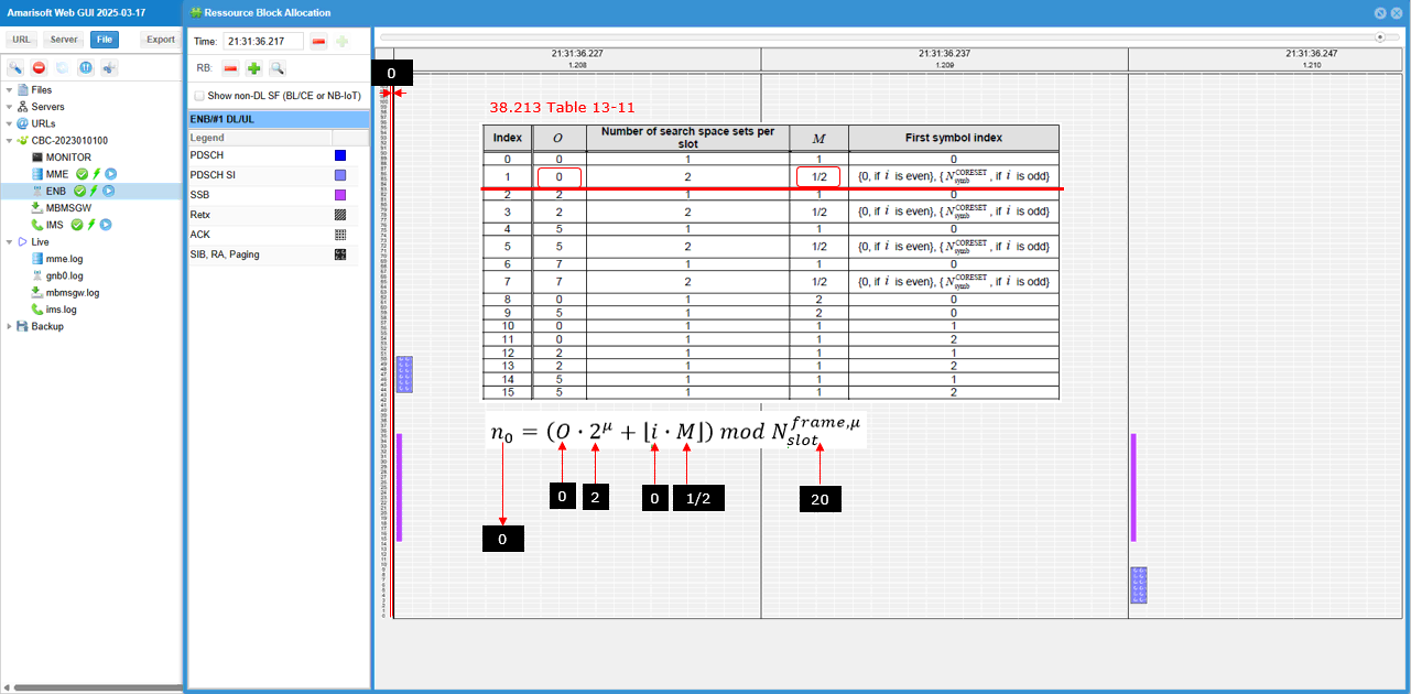
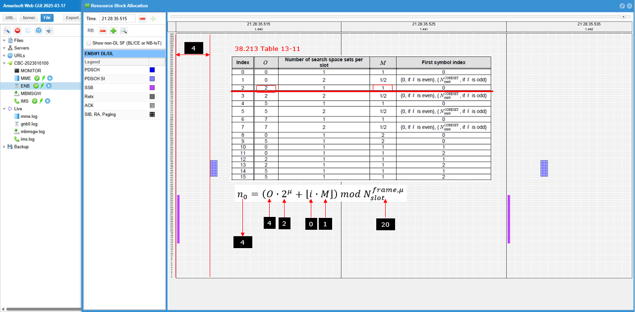
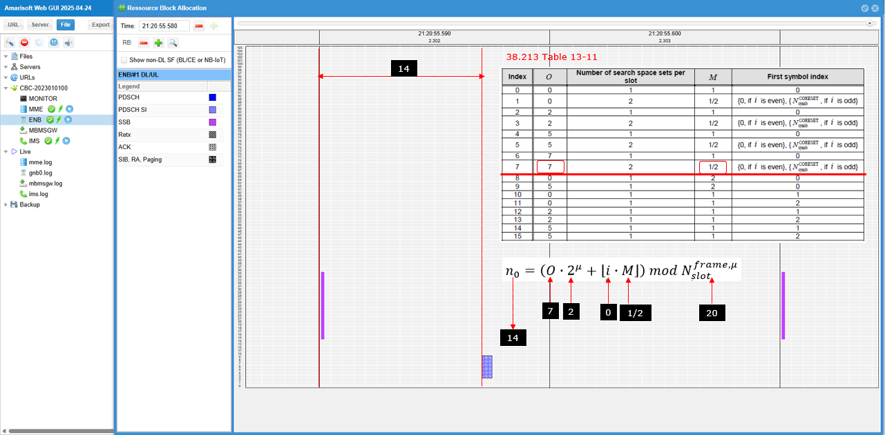
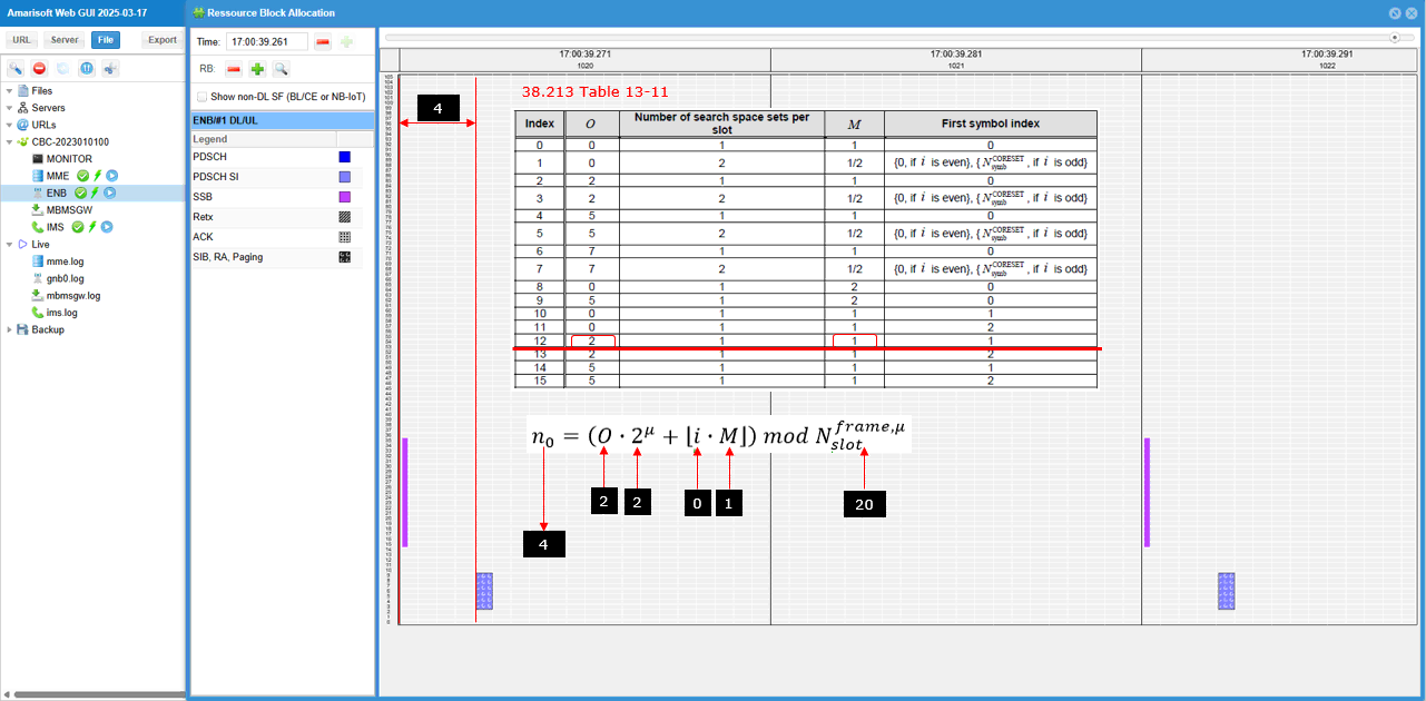
Now check out the location of search space 0 slot in RB map on WebGUI. The RB map does not explicitely plot the resource allocation for CORESET0 and SearchSpace0, but you can indirectly figure out the slot based on SIB1 PDSCH since CORESET0, SearchSpace0 and SIB1 PDSCH are all in the same slot.
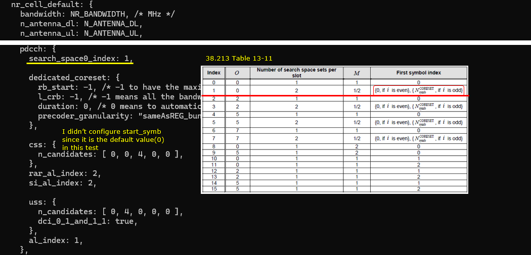
Sub Test 2 : SSB index 0, SearchSpace0 = 1
In this sub test, it will be shown where (in which slot) Search Space 0 is allocated for FR1 and Coreset0 Multiplexing Pattern 1. In this case, the search space 0 is allocated based on TS 38.213 - Table 13-11
Configuration
gnb-sa-searchspace0index-1.cfg is used for gNB configuration.
In gnb-sa-searchspace0index-1.cfg , gNB setting is configured as follows.
In this case, the cell is set to TDD (NR_TDD = 1) and the channel bandwidth (NR_BANDWIDTH) is set to 40 Mhz. You can set it to any bandwidth as long as it is valid for the specified band (You may refer to 38.101-1 regarding the valid channel bandwidth for a specific band)
I set "10000000" for SSB bitmap which indicates that the configured SSB index (i) is 0. Remember this index since it is one of the parameter to determine the time domain position of searchspace 0 according to TS 38.213
The search space0 is set to the index 1 of 38.213 Table 13-11 (search_space0_index = 1). In this case, the first symbol index (start_symb) is not configured since it is 0 (the default value of start_symb). You can explicitely set start_symb : 0 in css if you like.
Perform the Test
Start the lte service and check out the result of cell phy and see if the configuration is properly set as intended.
This is all you need to do for the test. You don't need to connect any UE for the test.
Log Analysis
For this test, it is important to collect MIB and BCCH and PHY layer log. A simple way to do it is to check MIB, BCCH and click [+] button in ENB configuration on WebGUI.
First check out the confents of MIB message and make it sure searchSpaceZero is configured as intended.
Now check out the location of search space 0 slot in RB map on WebGUI. The RB map does not explicitely plot the resource allocation for CORESET0 and SearchSpace0, but you can indirectly figure out the slot based on SIB1 PDSCH since CORESET0, SearchSpace0 and SIB1 PDSCH are all in the same slot.
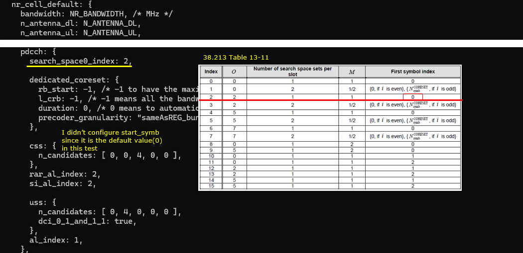
Sub Test 3 : SSB index 0, SearchSpace0 = 2
In this sub test, it will be shown where (in which slot) Search Space 0 is allocated for FR1 and Coreset0 Multiplexing Pattern 1. In this case, the search space 0 is allocated based on TS 38.213 - Table 13-11
Configuration
gnb-sa-searchspace0index-2.cfg is used for gNB configuration.

In gnb-sa-searchspace0index-2.cfg , gNB setting is configured as follows.
In this case, the cell is set to TDD (NR_TDD = 1) and the channel bandwidth (NR_BANDWIDTH) is set to 40 Mhz. You can set it to any bandwidth as long as it is valid for the specified band (You may refer to 38.101-1 regarding the valid channel bandwidth for a specific band)
I set "10000000" for SSB bitmap which indicates that the configured SSB index (i) is 0. Remember this index since it is one of the parameter to determine the time domain position of searchspace 0 according to TS 38.213
The search space0 is set to the index 2 of 38.213 Table 13-11 (search_space0_index = 2). In this case, the first symbol index (start_symb) is not configured since it is 0 (the default value of start_symb). You can explicitely set start_symb : 0 in css if you like.
Perform the Test
Start the lte service and check out the result of cell phy and see if the configuration is properly set as intended.
This is all you need to do for the test. You don't need to connect any UE for the test.
Log Analysis
For this test, it is important to collect MIB and BCCH and PHY layer log. A simple way to do it is to check MIB, BCCH and click [+] button in ENB configuration on WebGUI.
First check out the confents of MIB message and make it sure searchSpaceZero is configured as intended.
Now check out the location of search space 0 slot in RB map on WebGUI. The RB map does not explicitely plot the resource allocation for CORESET0 and SearchSpace0, but you can indirectly figure out the slot based on SIB1 PDSCH since CORESET0, SearchSpace0 and SIB1 PDSCH are all in the same slot.
Sub Test 4 : SSB index 0, SearchSpace0 = 3
In this sub test, it will be shown where (in which slot) Search Space 0 is allocated for FR1 and Coreset0 Multiplexing Pattern 1. In this case, the search space 0 is allocated based on TS 38.213 - Table 13-11
Configuration
gnb-sa-searchspace0index-3.cfg is used for gNB configuration.
In gnb-sa-searchspace0index-3.cfg , gNB setting is configured as follows.
In this case, the cell is set to TDD (NR_TDD = 1) and the channel bandwidth (NR_BANDWIDTH) is set to 40 Mhz. You can set it to any bandwidth as long as it is valid for the specified band (You may refer to 38.101-1 regarding the valid channel bandwidth for a specific band)
I set "10000000" for SSB bitmap which indicates that the configured SSB index (i) is 0. Remember this index since it is one of the parameter to determine the time domain position of searchspace 0 according to TS 38.213
The search space0 is set to the index 3 of 38.213 Table 13-11 (search_space0_index = 3). In this case, the first symbol index (start_symb) is not configured since it is 0 (the default value of start_symb). You can explicitely set start_symb : 0 in css if you like.
Perform the Test
Start the lte service and check out the result of cell phy and see if the configuration is properly set as intended.
This is all you need to do for the test. You don't need to connect any UE for the test.
Log Analysis
For this test, it is important to collect MIB and BCCH and PHY layer log. A simple way to do it is to check MIB, BCCH and click [+] button in ENB configuration on WebGUI.
First check out the confents of MIB message and make it sure searchSpaceZero is configured as intended.
Now check out the location of search space 0 slot in RB map on WebGUI. The RB map does not explicitely plot the resource allocation for CORESET0 and SearchSpace0, but you can indirectly figure out the slot based on SIB1 PDSCH since CORESET0, SearchSpace0 and SIB1 PDSCH are all in the same slot.
Sub Test 5 : SSB index 0, SearchSpace0 = 4
In this sub test, it will be shown where (in which slot) Search Space 0 is allocated for FR1 and Coreset0 Multiplexing Pattern 1. In this case, the search space 0 is allocated based on TS 38.213 - Table 13-11
Configuration
gnb-sa-searchspace0index-4.cfg is used for gNB configuration.

In gnb-sa-searchspace0index-4.cfg , gNB setting is configured as follows.
In this case, the cell is set to TDD (NR_TDD = 1) and the channel bandwidth (NR_BANDWIDTH) is set to 40 Mhz. You can set it to any bandwidth as long as it is valid for the specified band (You may refer to 38.101-1 regarding the valid channel bandwidth for a specific band)
I set "10000000" for SSB bitmap which indicates that the configured SSB index (i) is 0. Remember this index since it is one of the parameter to determine the time domain position of searchspace 0 according to TS 38.213
The search space0 is set to the index 4 of 38.213 Table 13-11 (search_space0_index = 4). In this case, the first symbol index (start_symb) is not configured since it is 0 (the default value of start_symb). You can explicitely set start_symb : 0 in css if you like.
Perform the Test
Start the lte service and check out the result of cell phy and see if the configuration is properly set as intended.
This is all you need to do for the test. You don't need to connect any UE for the test.
Log Analysis
For this test, it is important to collect MIB and BCCH and PHY layer log. A simple way to do it is to check MIB, BCCH and click [+] button in ENB configuration on WebGUI.
First check out the confents of MIB message and make it sure searchSpaceZero is configured as intended.
Now check out the location of search space 0 slot in RB map on WebGUI. The RB map does not explicitely plot the resource allocation for CORESET0 and SearchSpace0, but you can indirectly figure out the slot based on SIB1 PDSCH since CORESET0, SearchSpace0 and SIB1 PDSCH are all in the same slot.
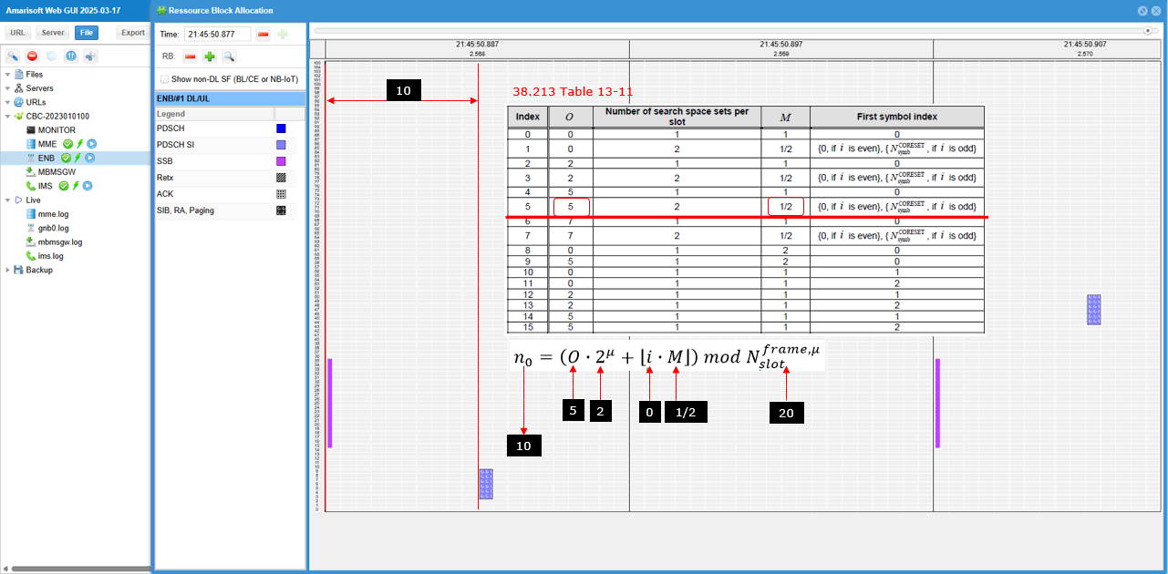
Sub Test 6 : SSB index 0, SearchSpace0 = 5
In this sub test, it will be shown where (in which slot) Search Space 0 is allocated for FR1 and Coreset0 Multiplexing Pattern 1. In this case, the search space 0 is allocated based on TS 38.213 - Table 13-11
Configuration
gnb-sa-searchspace0index-5.cfg is used for gNB configuration.
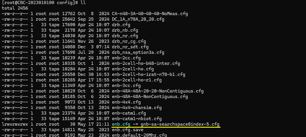
In gnb-sa-searchspace0index-5.cfg , gNB setting is configured as follows.
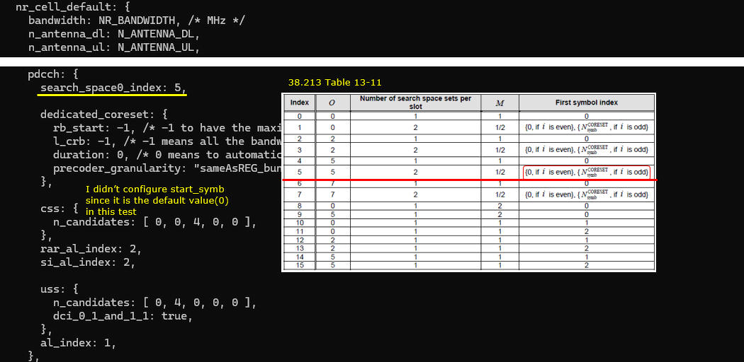
In this case, the cell is set to TDD (NR_TDD = 1) and the channel bandwidth (NR_BANDWIDTH) is set to 40 Mhz. You can set it to any bandwidth as long as it is valid for the specified band (You may refer to 38.101-1 regarding the valid channel bandwidth for a specific band)
I set "10000000" for SSB bitmap which indicates that the configured SSB index (i) is 0. Remember this index since it is one of the parameter to determine the time domain position of searchspace 0 according to TS 38.213
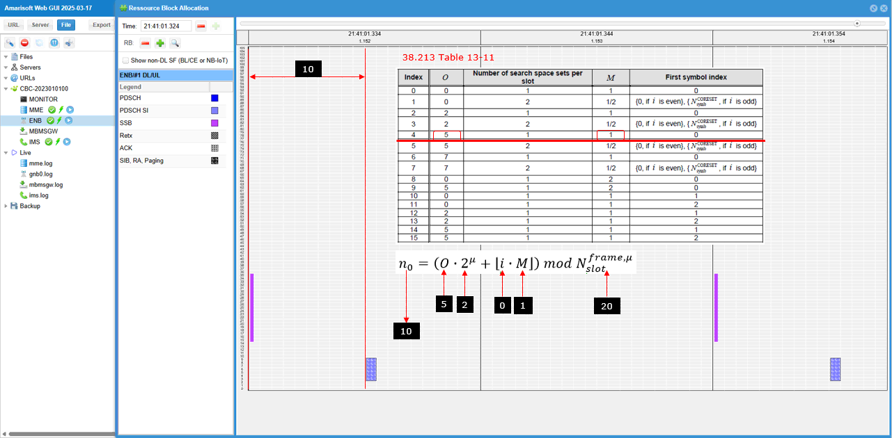
The search space0 is set to the index 5 of 38.213 Table 13-11 (search_space0_index = 5). In this case, the first symbol index (start_symb) is not configured since it is 0 (the default value of start_symb). You can explicitely set start_symb : 0 in css if you like.
Perform the Test
Start the lte service and check out the result of cell phy and see if the configuration is properly set as intended.
This is all you need to do for the test. You don't need to connect any UE for the test.
Log Analysis
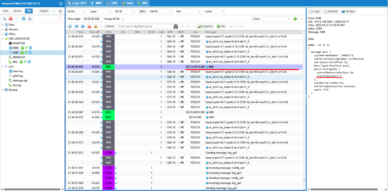
For this test, it is important to collect MIB and BCCH and PHY layer log. A simple way to do it is to check MIB, BCCH and click [+] button in ENB configuration on WebGUI.
First check out the confents of MIB message and make it sure searchSpaceZero is configured as intended.
Now check out the location of search space 0 slot in RB map on WebGUI. The RB map does not explicitely plot the resource allocation for CORESET0 and SearchSpace0, but you can indirectly figure out the slot based on SIB1 PDSCH since CORESET0, SearchSpace0 and SIB1 PDSCH are all in the same slot.
Sub Test 7 : SSB index 0, SearchSpace0 = 6
In this sub test, it will be shown where (in which slot) Search Space 0 is allocated for FR1 and Coreset0 Multiplexing Pattern 1. In this case, the search space 0 is allocated based on TS 38.213 - Table 13-11
Configuration
gnb-sa-searchspace0index-6.cfg is used for gNB configuration.

In gnb-sa-searchspace0index-6.cfg , gNB setting is configured as follows.
In this case, the cell is set to TDD (NR_TDD = 1) and the channel bandwidth (NR_BANDWIDTH) is set to 40 Mhz. You can set it to any bandwidth as long as it is valid for the specified band (You may refer to 38.101-1 regarding the valid channel bandwidth for a specific band)
I set "10000000" for SSB bitmap which indicates that the configured SSB index (i) is 0. Remember this index since it is one of the parameter to determine the time domain position of searchspace 0 according to TS 38.213
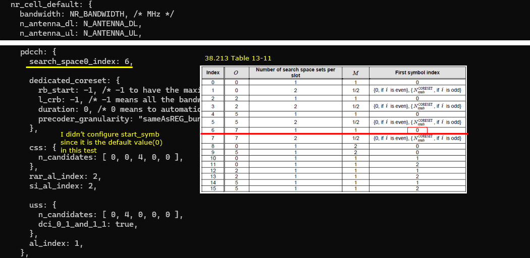
The search space0 is set to the index 6 of 38.213 Table 13-11 (search_space0_index = 6). In this case, the first symbol index (start_symb) is not configured since it is 0 (the default value of start_symb). You can explicitely set start_symb : 0 in css if you like.
Perform the Test
Start the lte service and check out the result of cell phy and see if the configuration is properly set as intended.
This is all you need to do for the test. You don't need to connect any UE for the test.
Log Analysis
For this test, it is important to collect MIB and BCCH and PHY layer log. A simple way to do it is to check MIB, BCCH and click [+] button in ENB configuration on WebGUI.
First check out the confents of MIB message and make it sure searchSpaceZero is configured as intended.
Now check out the location of search space 0 slot in RB map on WebGUI. The RB map does not explicitely plot the resource allocation for CORESET0 and SearchSpace0, but you can indirectly figure out the slot based on SIB1 PDSCH since CORESET0, SearchSpace0 and SIB1 PDSCH are all in the same slot.
Sub Test 8 : SSB index 0, SearchSpace0 = 7
In this sub test, it will be shown where (in which slot) Search Space 0 is allocated for FR1 and Coreset0 Multiplexing Pattern 1. In this case, the search space 0 is allocated based on TS 38.213 - Table 13-11
Configuration
gnb-sa-searchspace0index-7.cfg is used for gNB configuration.
In gnb-sa-searchspace0index-7.cfg , gNB setting is configured as follows.
In this case, the cell is set to TDD (NR_TDD = 1) and the channel bandwidth (NR_BANDWIDTH) is set to 40 Mhz. You can set it to any bandwidth as long as it is valid for the specified band (You may refer to 38.101-1 regarding the valid channel bandwidth for a specific band)
I set "10000000" for SSB bitmap which indicates that the configured SSB index (i) is 0. Remember this index since it is one of the parameter to determine the time domain position of searchspace 0 according to TS 38.213
The search space0 is set to the index 7 of 38.213 Table 13-11 (search_space0_index = 7). In this case, the first symbol index (start_symb) is not configured since it is 0 (the default value of start_symb). You can explicitely set start_symb : 0 in css if you like.

Perform the Test
Start the lte service and check out the result of cell phy and see if the configuration is properly set as intended.
This is all you need to do for the test. You don't need to connect any UE for the test.
Log Analysis
For this test, it is important to collect MIB and BCCH and PHY layer log. A simple way to do it is to check MIB, BCCH and click [+] button in ENB configuration on WebGUI.
First check out the confents of MIB message and make it sure searchSpaceZero is configured as intended.
Now check out the location of search space 0 slot in RB map on WebGUI. The RB map does not explicitely plot the resource allocation for CORESET0 and SearchSpace0, but you can indirectly figure out the slot based on SIB1 PDSCH since CORESET0, SearchSpace0 and SIB1 PDSCH are all in the same slot.
Sub Test 9 : SSB index 0, SearchSpace0 = 8
In this sub test, it will be shown where (in which slot) Search Space 0 is allocated for FR1 and Coreset0 Multiplexing Pattern 1. In this case, the search space 0 is allocated based on TS 38.213 - Table 13-11
Configuration
gnb-sa-searchspace0index-8.cfg is used for gNB configuration.

In gnb-sa-searchspace0index-8.cfg , gNB setting is configured as follows.
In this case, the cell is set to TDD (NR_TDD = 1) and the channel bandwidth (NR_BANDWIDTH) is set to 40 Mhz. You can set it to any bandwidth as long as it is valid for the specified band (You may refer to 38.101-1 regarding the valid channel bandwidth for a specific band)
I set "10000000" for SSB bitmap which indicates that the configured SSB index (i) is 0. Remember this index since it is one of the parameter to determine the time domain position of searchspace 0 according to TS 38.213
The search space0 is set to the index 8 of 38.213 Table 13-11 (search_space0_index = 8). In this case, the first symbol index (start_symb) is not configured since it is 0 (the default value of start_symb). You can explicitely set start_symb : 0 in css if you like.
Perform the Test
Start the lte service and check out the result of cell phy and see if the configuration is properly set as intended.
This is all you need to do for the test. You don't need to connect any UE for the test.
Log Analysis
For this test, it is important to collect MIB and BCCH and PHY layer log. A simple way to do it is to check MIB, BCCH and click [+] button in ENB configuration on WebGUI.
First check out the confents of MIB message and make it sure searchSpaceZero is configured as intended.
Now check out the location of search space 0 slot in RB map on WebGUI. The RB map does not explicitely plot the resource allocation for CORESET0 and SearchSpace0, but you can indirectly figure out the slot based on SIB1 PDSCH since CORESET0, SearchSpace0 and SIB1 PDSCH are all in the same slot.
Sub Test 10 : SSB index 0, SearchSpace0 = 9
In this sub test, it will be shown where (in which slot) Search Space 0 is allocated for FR1 and Coreset0 Multiplexing Pattern 1. In this case, the search space 0 is allocated based on TS 38.213 - Table 13-11
Configuration
gnb-sa-searchspace0index-9.cfg is used for gNB configuration.
In gnb-sa-searchspace0index-9.cfg , gNB setting is configured as follows.
In this case, the cell is set to TDD (NR_TDD = 1) and the channel bandwidth (NR_BANDWIDTH) is set to 40 Mhz. You can set it to any bandwidth as long as it is valid for the specified band (You may refer to 38.101-1 regarding the valid channel bandwidth for a specific band)
I set "10000000" for SSB bitmap which indicates that the configured SSB index (i) is 0. Remember this index since it is one of the parameter to determine the time domain position of searchspace 0 according to TS 38.213
The search space0 is set to the index 9 of 38.213 Table 13-11 (search_space0_index = 9). In this case, the first symbol index (start_symb) is not configured since it is 0 (the default value of start_symb). You can explicitely set start_symb : 0 in css if you like.

Perform the Test
Start the lte service and check out the result of cell phy and see if the configuration is properly set as intended.
This is all you need to do for the test. You don't need to connect any UE for the test.
Log Analysis
For this test, it is important to collect MIB and BCCH and PHY layer log. A simple way to do it is to check MIB, BCCH and click [+] button in ENB configuration on WebGUI.
First check out the confents of MIB message and make it sure searchSpaceZero is configured as intended.
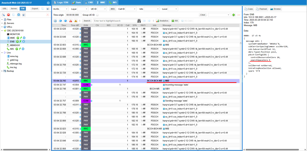
Now check out the location of search space 0 slot in RB map on WebGUI. The RB map does not explicitely plot the resource allocation for CORESET0 and SearchSpace0, but you can indirectly figure out the slot based on SIB1 PDSCH since CORESET0, SearchSpace0 and SIB1 PDSCH are all in the same slot.
Sub Test 11 : SSB index 0, SearchSpace0 = 10
In this sub test, it will be shown where (in which slot) Search Space 0 is allocated for FR1 and Coreset0 Multiplexing Pattern 1. In this case, the search space 0 is allocated based on TS 38.213 - Table 13-11
Configuration
gnb-sa-searchspace0index-10.cfg is used for gNB configuration.
In gnb-sa-searchspace0index-10.cfg , gNB setting is configured as follows.
In this case, the cell is set to TDD (NR_TDD = 1) and the channel bandwidth (NR_BANDWIDTH) is set to 40 Mhz. You can set it to any bandwidth as long as it is valid for the specified band (You may refer to 38.101-1 regarding the valid channel bandwidth for a specific band)
I set "10000000" for SSB bitmap which indicates that the configured SSB index (i) is 0. Remember this index since it is one of the parameter to determine the time domain position of searchspace 0 according to TS 38.213
The search space0 is set to the index 10 of 38.213 Table 13-11 (search_space0_index = 10). In this case, the first symbol index (start_symb) is not configured since it is 0 (the default value of start_symb). You can explicitely set start_symb : 0 in css if you like.
Perform the Test
Start the lte service and check out the result of cell phy and see if the configuration is properly set as intended.
This is all you need to do for the test. You don't need to connect any UE for the test.
Log Analysis
For this test, it is important to collect MIB and BCCH and PHY layer log. A simple way to do it is to check MIB, BCCH and click [+] button in ENB configuration on WebGUI.
First check out the confents of MIB message and make it sure searchSpaceZero is configured as intended.
Now check out the location of search space 0 slot in RB map on WebGUI. The RB map does not explicitely plot the resource allocation for CORESET0 and SearchSpace0, but you can indirectly figure out the slot based on SIB1 PDSCH since CORESET0, SearchSpace0 and SIB1 PDSCH are all in the same slot.
Sub Test 12 : SSB index 1, SearchSpace0 = 11
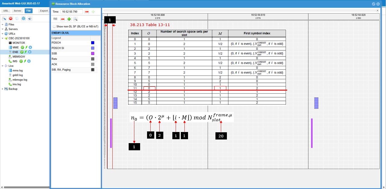
In this sub test, it will be shown where (in which slot) Search Space 0 is allocated for FR1 and Coreset0 Multiplexing Pattern 1. In this case, the search space 0 is allocated based on TS 38.213 - Table 13-11
Configuration
gnb-sa-searchspace0index-11.cfg is used for gNB configuration.

In gnb-sa-searchspace0index-11.cfg , gNB setting is configured as follows.
In this case, the cell is set to TDD (NR_TDD = 1) and the channel bandwidth (NR_BANDWIDTH) is set to 40 Mhz. You can set it to any bandwidth as long as it is valid for the specified band (You may refer to 38.101-1 regarding the valid channel bandwidth for a specific band)
I set "01000000" for SSB bitmap which indicates that the configured SSB index (i) is 1. Remember this index since it is one of the parameter to determine the time domain position of searchspace 0 according to TS 38.213 (

The search space0 is set to the index 11 of 38.213 Table 13-11 (search_space0_index = 11). In this case, the first symbol index (start_symb) is not configured since it is 0 (the default value of start_symb). You can explicitely set start_symb : 0 in css if you like.
Perform the Test
Start the lte service and check out the result of cell phy and see if the configuration is properly set as intended.
This is all you need to do for the test. You don't need to connect any UE for the test.
Log Analysis
For this test, it is important to collect MIB and BCCH and PHY layer log. A simple way to do it is to check MIB, BCCH and click [+] button in ENB configuration on WebGUI.
First check out the confents of MIB message and make it sure searchSpaceZero is configured as intended.
Now check out the location of search space 0 slot in RB map on WebGUI. The RB map does not explicitely plot the resource allocation for CORESET0 and SearchSpace0, but you can indirectly figure out the slot based on SIB1 PDSCH since CORESET0, SearchSpace0 and SIB1 PDSCH are all in the same slot.
Sub Test 13 : SSB index 0, SearchSpace0 = 12
In this sub test, it will be shown where (in which slot) Search Space 0 is allocated for FR1 and Coreset0 Multiplexing Pattern 1. In this case, the search space 0 is allocated based on TS 38.213 - Table 13-11
Configuration
gnb-sa-searchspace0index-12.cfg is used for gNB configuration.

In gnb-sa-searchspace0index-12.cfg , gNB setting is configured as follows.
In this case, the cell is set to TDD (NR_TDD = 1) and the channel bandwidth (NR_BANDWIDTH) is set to 40 Mhz. You can set it to any bandwidth as long as it is valid for the specified band (You may refer to 38.101-1 regarding the valid channel bandwidth for a specific band)
I set "10000000" for SSB bitmap which indicates that the configured SSB index (i) is 0. Remember this index since it is one of the parameter to determine the time domain position of searchspace 0 according to TS 38.213
The search space0 is set to the index 12 of 38.213 Table 13-11 (search_space0_index = 12). In this case, the first symbol index (start_symb) is not configured since it is 0 (the default value of start_symb). You can explicitely set start_symb : 0 in css if you like.
Perform the Test
Start the lte service and check out the result of cell phy and see if the configuration is properly set as intended.
This is all you need to do for the test. You don't need to connect any UE for the test.
Log Analysis
For this test, it is important to collect MIB and BCCH and PHY layer log. A simple way to do it is to check MIB, BCCH and click [+] button in ENB configuration on WebGUI.
First check out the confents of MIB message and make it sure searchSpaceZero is configured as intended.
Now check out the location of search space 0 slot in RB map on WebGUI. The RB map does not explicitely plot the resource allocation for CORESET0 and SearchSpace0, but you can indirectly figure out the slot based on SIB1 PDSCH since CORESET0, SearchSpace0 and SIB1 PDSCH are all in the same slot.
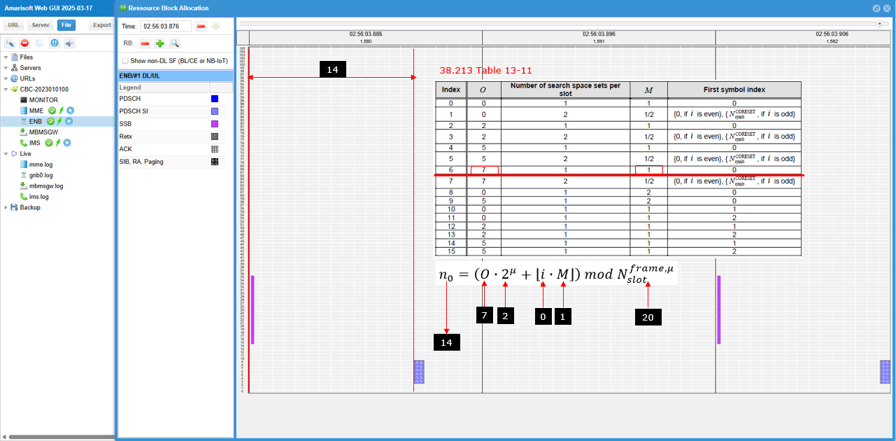
Sub Test 14 : SSB index 1, SearchSpace0 = 13
In this sub test, it will be shown where (in which slot) Search Space 0 is allocated for FR1 and Coreset0 Multiplexing Pattern 1. In this case, the search space 0 is allocated based on TS 38.213 - Table 13-11
Configuration
gnb-sa-searchspace0index-13.cfg is used for gNB configuration.

In gnb-sa-searchspace0index-13.cfg , gNB setting is configured as follows.
In this case, the cell is set to TDD (NR_TDD = 1) and the channel bandwidth (NR_BANDWIDTH) is set to 40 Mhz. You can set it to any bandwidth as long as it is valid for the specified band (You may refer to 38.101-1 regarding the valid channel bandwidth for a specific band)
I set "01000000" for SSB bitmap which indicates that the configured SSB index (i) is 1. Remember this index since it is one of the parameter to determine the time domain position of searchspace 0 according to TS 38.213 (
The search space0 is set to the index 13 of 38.213 Table 13-11 (search_space0_index = 13). In this case, the first symbol index (start_symb) is not configured since it is 0 (the default value of start_symb). You can explicitely set start_symb : 0 in css if you like.

Perform the Test
Start the lte service and check out the result of cell phy and see if the configuration is properly set as intended.
This is all you need to do for the test. You don't need to connect any UE for the test.
Log Analysis
For this test, it is important to collect MIB and BCCH and PHY layer log. A simple way to do it is to check MIB, BCCH and click [+] button in ENB configuration on WebGUI.
First check out the confents of MIB message and make it sure searchSpaceZero is configured as intended.
Now check out the location of search space 0 slot in RB map on WebGUI. The RB map does not explicitely plot the resource allocation for CORESET0 and SearchSpace0, but you can indirectly figure out the slot based on SIB1 PDSCH since CORESET0, SearchSpace0 and SIB1 PDSCH are all in the same slot.
Sub Test 15 : SSB index 0, SearchSpace0 = 14
In this sub test, it will be shown where (in which slot) Search Space 0 is allocated for FR1 and Coreset0 Multiplexing Pattern 1. In this case, the search space 0 is allocated based on TS 38.213 - Table 13-11
Configuration
gnb-sa-searchspace0index-14.cfg is used for gNB configuration.
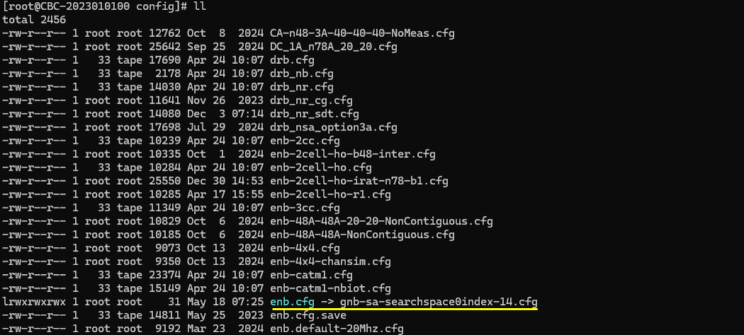
In gnb-sa-searchspace0index-14.cfg , gNB setting is configured as follows.
In this case, the cell is set to TDD (NR_TDD = 1) and the channel bandwidth (NR_BANDWIDTH) is set to 40 Mhz. You can set it to any bandwidth as long as it is valid for the specified band (You may refer to 38.101-1 regarding the valid channel bandwidth for a specific band)
I set "10000000" for SSB bitmap which indicates that the configured SSB index (i) is 0. Remember this index since it is one of the parameter to determine the time domain position of searchspace 0 according to TS 38.213
The search space0 is set to the index 14 of 38.213 Table 13-11 (search_space0_index = 14). In this case, the first symbol index (start_symb) is not configured since it is 0 (the default value of start_symb). You can explicitely set start_symb : 0 in css if you like.

Perform the Test
Start the lte service and check out the result of cell phy and see if the configuration is properly set as intended.
This is all you need to do for the test. You don't need to connect any UE for the test.
Log Analysis
For this test, it is important to collect MIB and BCCH and PHY layer log. A simple way to do it is to check MIB, BCCH and click [+] button in ENB configuration on WebGUI.
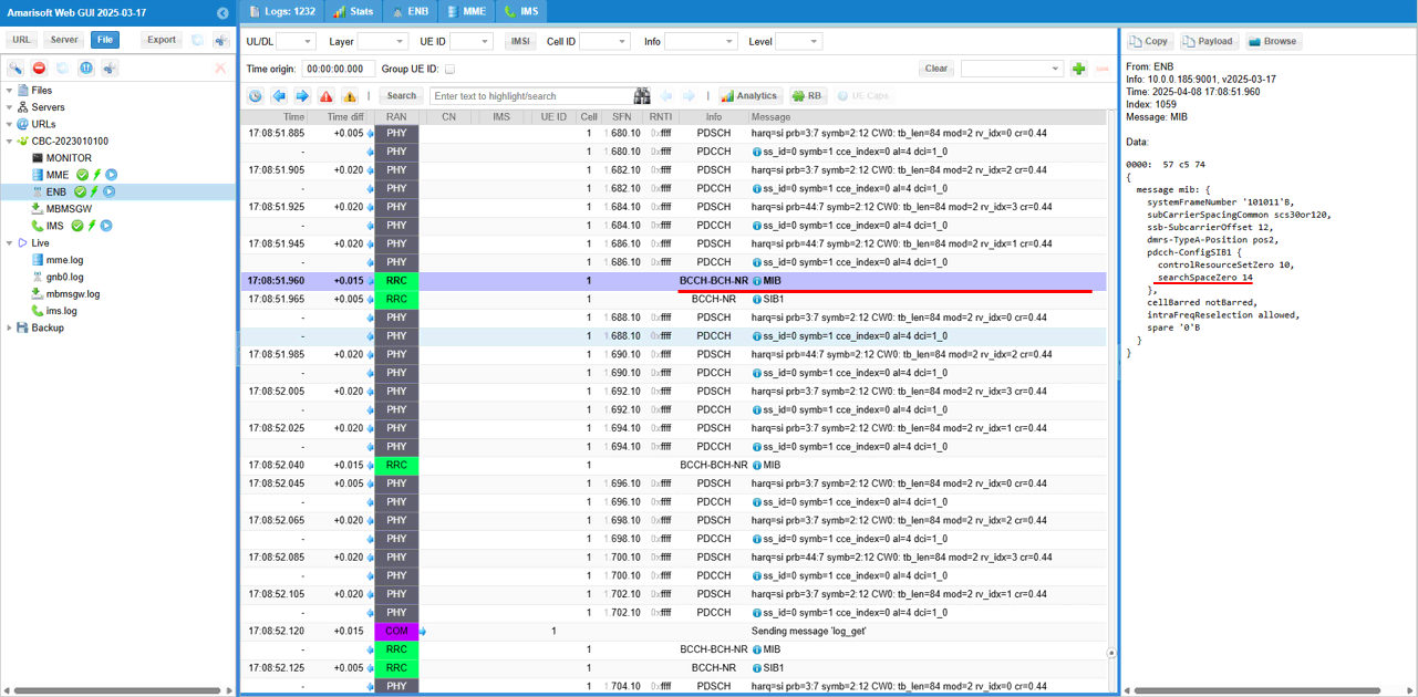
First check out the confents of MIB message and make it sure searchSpaceZero is configured as intended.
Now check out the location of search space 0 slot in RB map on WebGUI. The RB map does not explicitely plot the resource allocation for CORESET0 and SearchSpace0, but you can indirectly figure out the slot based on SIB1 PDSCH since CORESET0, SearchSpace0 and SIB1 PDSCH are all in the same slot.
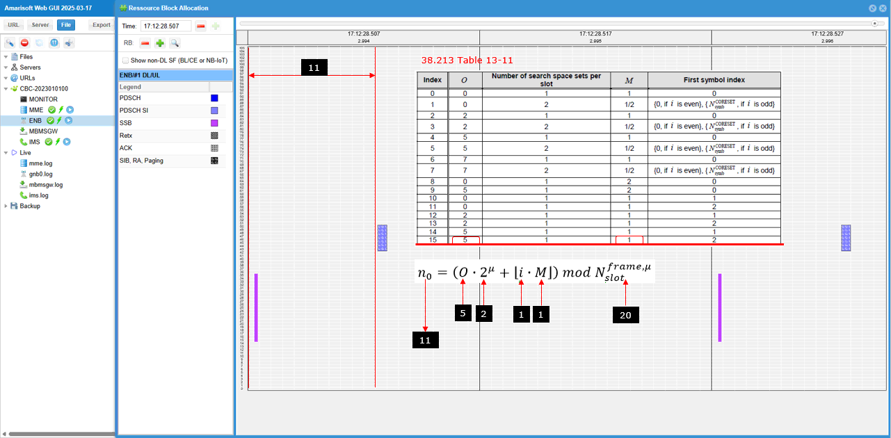
Sub Test 16 : SSB index 1, SearchSpace0 = 15
In this sub test, it will be shown where (in which slot) Search Space 0 is allocated for FR1 and Coreset0 Multiplexing Pattern 1. In this case, the search space 0 is allocated based on TS 38.213 - Table 13-11
Configuration
gnb-sa-searchspace0index-15.cfg is used for gNB configuration.
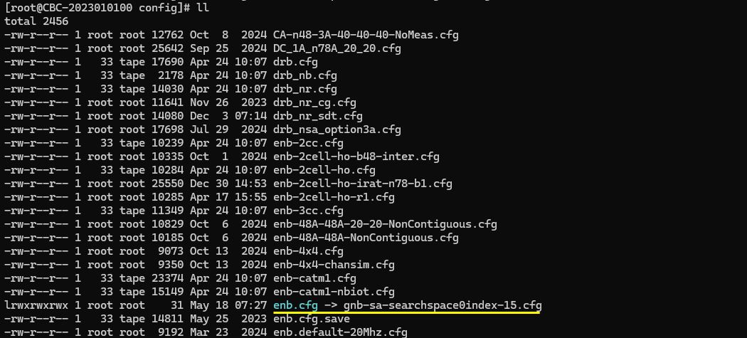
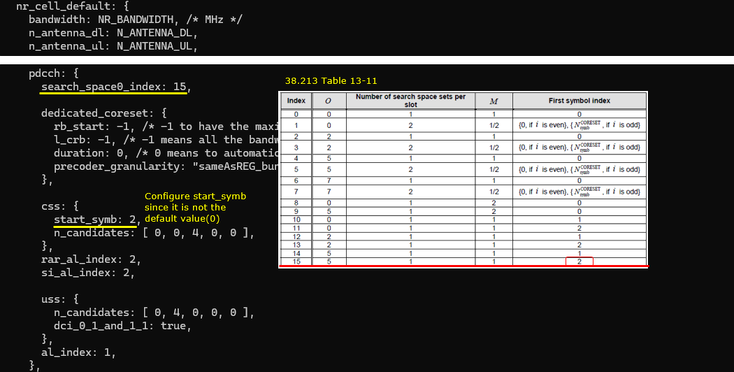
In gnb-sa-searchspace0index-15.cfg , gNB setting is configured as follows.
In this case, the cell is set to TDD (NR_TDD = 1) and the channel bandwidth (NR_BANDWIDTH) is set to 40 Mhz. You can set it to any bandwidth as long as it is valid for the specified band (You may refer to 38.101-1 regarding the valid channel bandwidth for a specific band)
I set "01000000" for SSB bitmap which indicates that the configured SSB index (i) is 1. Remember this index since it is one of the parameter to determine the time domain position of searchspace 0 according to TS 38.213 (

The search space0 is set to the index 15 of 38.213 Table 13-11 (search_space0_index = 15). In this case, the first symbol index (start_symb) is not configured since it is 0 (the default value of start_symb). You can explicitely set start_symb : 0 in css if you like.
Perform the Test
Start the lte service and check out the result of cell phy and see if the configuration is properly set as intended.
This is all you need to do for the test. You don't need to connect any UE for the test.
Log Analysis
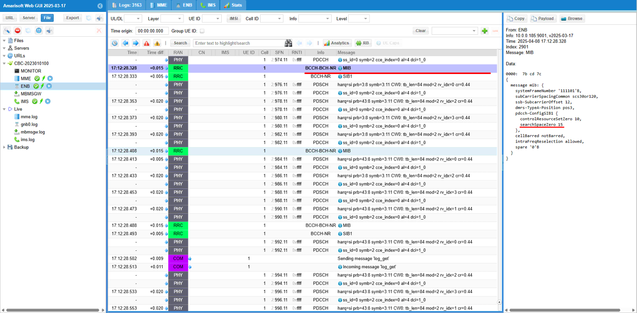
For this test, it is important to collect MIB and BCCH and PHY layer log. A simple way to do it is to check MIB, BCCH and click [+] button in ENB configuration on WebGUI.
First check out the confents of MIB message and make it sure searchSpaceZero is configured as intended.
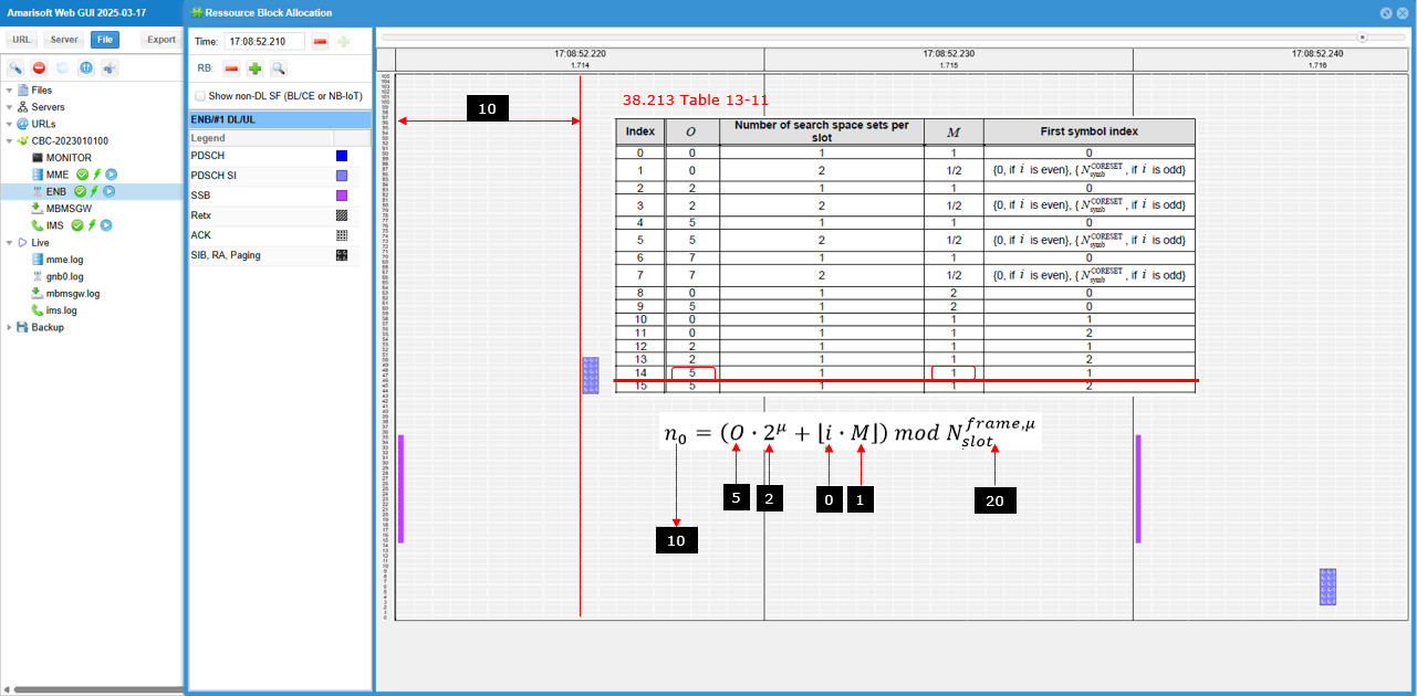
Now check out the location of search space 0 slot in RB map on WebGUI. The RB map does not explicitely plot the resource allocation for CORESET0 and SearchSpace0, but you can indirectly figure out the slot based on SIB1 PDSCH since CORESET0, SearchSpace0 and SIB1 PDSCH are all in the same slot.
RRC / NAS Signaling
MIB (SA)
: Amarisoft Callbox does not print out the full contents of MIB (PBCH) in the trace log (The MIB contents related to CORESET 0 is printed in the log at meta data section as shown above). The ASN.1 structure of NR SA MIB is as shown below.
