NR SA - SSB / CSI RS
The purpose of this tutorial is a little straightforward. it is about how to change SSB bitmap, but implementation is not that simple because just increasing the number of active bits in SSB bitmap may cause collision of other signals for example coliision with CSI RS as shown below.

To resolve this kind of collision, you may need to change the resource allocation of other signals (e.g, CSI RS) to avoid the collision with the SSB. What I am going to show you in this tutorial is to change the resource allocation of CSI RS when the number of active bits in SSB bitmap is increased.
Table of Contents
Introduction
In 5G NR (New Radio) systems, Synchronization Signal Blocks (SSBs) play a critical role in enabling initial access, beam management, and mobility operations for user equipment (UE). The SSB bitmap determines which SSB beams are active, directly influencing the coverage and capacity of the gNB (next-generation NodeB) cell. However, modifying the SSB bitmap—particularly by increasing the number of active SSB beams—can introduce complexities within the radio frame, specifically due to the risk of resource collisions with other downlink signals such as Channel State Information Reference Signals (CSI-RS). The NR frame structure is carefully partitioned, and overlapping resource allocations can degrade system performance or cause signaling failures. Therefore, proper coordination and reconfiguration of signal resource allocations are essential when adjusting the SSB bitmap. This tutorial addresses the technical challenges associated with modifying the SSB bitmap, focusing on how to resolve potential collisions with CSI-RS. By guiding you through the process of adjusting CSI-RS resource allocations in response to changes in the SSB bitmap, this tutorial ensures that you can maintain robust and efficient network operation while extending SSB coverage or enhancing beamforming capabilities. The concepts and procedures discussed here are integral to the effective deployment and optimization of 5G NR networks, reflecting the intricate balance required in radio resource planning and management.
-
Context and Background
- 5G NR relies on precise synchronization and reference signaling, where SSB and CSI-RS are crucial for network access and performance optimization.
- The SSB bitmap defines which beams are broadcast, affecting the cell's synchronization coverage and the initial access process for UEs.
- Resource allocation for downlink signals is governed by the NR frame structure, requiring careful planning to avoid signal overlap and collisions.
-
Relevance and Importance of the Tutorial
- Understanding how to safely modify the SSB bitmap is vital for network engineers seeking to expand coverage or improve beam management.
- Avoiding resource collisions, particularly with CSI-RS, ensures reliable UE measurements and optimal network throughput.
- This tutorial addresses a practical and frequently encountered challenge in NR network deployment and optimization.
-
Learning Outcomes
- Gain a detailed understanding of the interplay between SSB and CSI-RS resource allocations in NR systems.
- Learn the technical steps required to adjust CSI-RS resource allocation when increasing the number of active SSBs.
- Acquire best practices for avoiding signal collisions and maintaining network performance following SSB bitmap changes.
-
Prerequisite Knowledge
- Familiarity with 5G NR architecture, especially SSB and CSI-RS concepts.
- Understanding of NR frame structure and resource allocation principles.
- Basic experience with gNB configuration and NR signal planning.
Summary of the Tutorial
This tutorial outlines the procedure for low-layer testing of SSB bitmap configuration and CSI-RS resource allocation in an NR (5G) system using Amarisoft tools. The focus is on ensuring that SSB and CSI-RS resources do not collide, particularly with all SSB positions enabled.
-
Test Setup:
- Uses the default SIM card provided with the system.
- Test is performed on low-layer signaling; no complex IP layer setup is required.
- Reference diagrams are used to visualize physical resource allocations for SSB and CSI-RS.
-
Key Configuration Parameters:
- ssb_pos_bitmap: Set to "11111111" to enable all SSB bursts.
- csi_rs and associated parameters (e.g., nzp_csi_rs_resource, csi_im_resource, zp_csi_rs_resource, etc.): These are carefully configured to prevent resource collisions with SSB.
- TDD Mode: TDD is used as the duplex mode, with DL/UL configuration set to NR_TDD_CONFIG 2.
-
Test Procedure:
-
1. Resource Allocation Planning:
- Draw diagrams to map out the allocation of SSB, PDCCH, and PDSCH resources, marking which slots/symbols are allowed for CSI-RS.
- Allocate CSI-RS resources to available symbols and slots where they will not overlap with SSB bursts.
-
2. Configuration:
- Use the configuration file gnb-sa-ssb-11111111.cfg, modified from a sample configuration.
- Set ssb_pos_bitmap to enable all SSB positions.
- Configure CSI-RS resources (frequency_domain_allocation, cdm_type, n_ports, first_symb, offset, etc.) to avoid collisions with SSB.
- Set up csi-im resource for interference measurement, ensuring symbol_location and offset do not overlap with SSB.
- Configure blank resource elements within PDSCH RB to avoid SSB bursts.
- Use default IMS and MME configuration files as provided.
-
3. Test Execution:
- Verify physical layer configuration in the cell.
- Power on the UE, wait for initial attach, and confirm that PHY data is being transmitted.
-
4. Log Analysis:
- Confirm SSB positions using SIB1 information; verify the ssb-PositionInBurst field matches configuration.
- Check CSI-RS-related elements to ensure they are not colliding with SSB in slots or symbols.
- Analyze IE fields such as zp-CSI-RS-ResourceToAddModList, nzp-CSI-RS-ResourceToAddModList, and csi-IM-ResourceToAddModList to confirm proper configuration and non-overlapping resource assignment.
- Validate that CSI reports are received as expected, confirming that the SSB burst configuration does not interfere with CSI reporting.
-
1. Resource Allocation Planning:
Summary of Methodology:
- Plan and visualize resource allocation to prevent signal overlap.
- Configure SSB and CSI-RS parameters in the gNB configuration, ensuring all SSB bits are enabled and CSI-RS resources are collision-free.
- Execute the test by powering on the UE and confirming system attach and PHY data flow.
- Analyze logs and configuration mappings to validate that all signal resources are allocated as intended and verify the absence of collisions.
This procedure ensures robust configuration and testing of SSB and CSI-RS coexistence, focusing on resource separation and verification through both configuration checks and real-time log analysis.
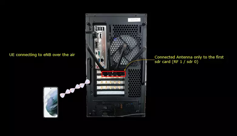
Test Setup
Test setup for this tutorial is as shown below. This is just for low layer testing, you may not need any complicated IP layer setup.
- SIM Card used in this tutorial is the one delivered with the system as it is.
- If you want to change the configuration, The tutorial Configuration Guide would help
Key Configuration Parameters
Followings are important configuration parameters for this tutorial. You may click on the items for the descriptions from Amarisoft documents.
- ssb_pos_bitmap
- csi_rs
- nzp_csi_rs_resource : In this link, you can find the descriptions for all the parameters below.
- csi_rs_id
- n_ports
- frequency_domain_allocation
- cdm_type
- density
- first_symb
- first_symb2
- rb_start
- l_crb
- period
- offset
- qcl_info_periodic_csi_rs
- csi_im_resource : In this link, you can find the descriptions for all the parameters below.
- csi_im_id
- pattern
- subcarrier_location
- symbol_location
- rb_start
- l_crb
- period
- offset
- zp_csi_rs_resource : In this link, you can find the descriptions for all the parameters below.
- csi_rs_id
- n_ports
- frequency_domain_allocation
- cdm_type
- density
- first_symb
- first_symb2
- rb_start
- l_crb
- period
- offset
- nzp_csi_rs_resource_set : In this link, you can find the descriptions for all the parameters below.
- csi_rs_set_id
- nzp_csi_rs_resources
- repetition
- trs_info
- csi_im_resource_set : In this link, you can find the descriptions for all the parameters below.
- csi_im_set_id
- csi_im_resources
Test 1 : n78, Case C - SSB bitmap 11111111
In this test, I will show you the case where all of the SSB bits are enabled. Enabling the ssb bit is very simple.. changing just one parameter is enough but the problem rises in the case where the enabled SSB bit collides with other signals especially with CSI-RS. You may need to change CSI-RS so that it does not collide with the enabled SSB. It would not be easy to change CSI-RS properly without clear picture in your mind. So my recommendation is to draw some picture showing the physical resources for various physical signals as shown below. In this test, it is assumed that TDD_Config 2 of our sample configuration : gnb-sa.cfg.
First draw a picture showing all the major physical signal resources except CSI-RS and mark which slots/symbols are allowed for CSI-RS and which are not allowed as shown below.

Then allocate the various CSI-RS to any of the allowed slots/symbols. There can be many possibilities, but following diagram shows only one of those possibilities and this will configured into the configuration file for this test.

Configuration
The configuration shown here is common configuration for all the subtests belonging to Test 1 and I will not show this configuration repeatedly for every subtest.
I have used gnb-sa-ssb-11111111.cfg which is copied and modified from gnb-sa.cfg

I am using the default mme, ims config as shown below. ims.default.cfg is used for ims.cfg and mme-ims.cfg is used for mme.cfg

In gnb-sa-ssb-11111111.cfg , it is configured as follows.
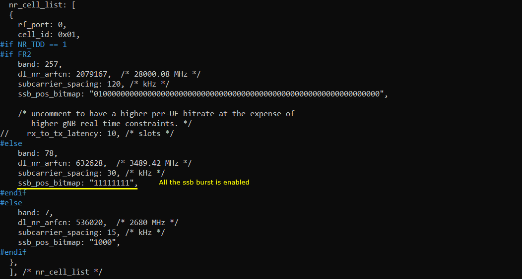
TDD is used for duplex mode and TDD DL/UL configuration is set to NR_TDD_CONFIG 2. This is one of the preconfigured set in the configuration file provided by sample configuration.

In this example, ssb_pos_bitmap is set to "11111111" meaning that every SSB burst is activated.
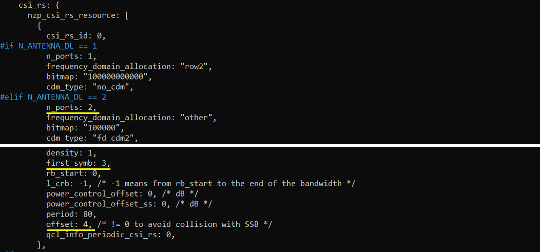
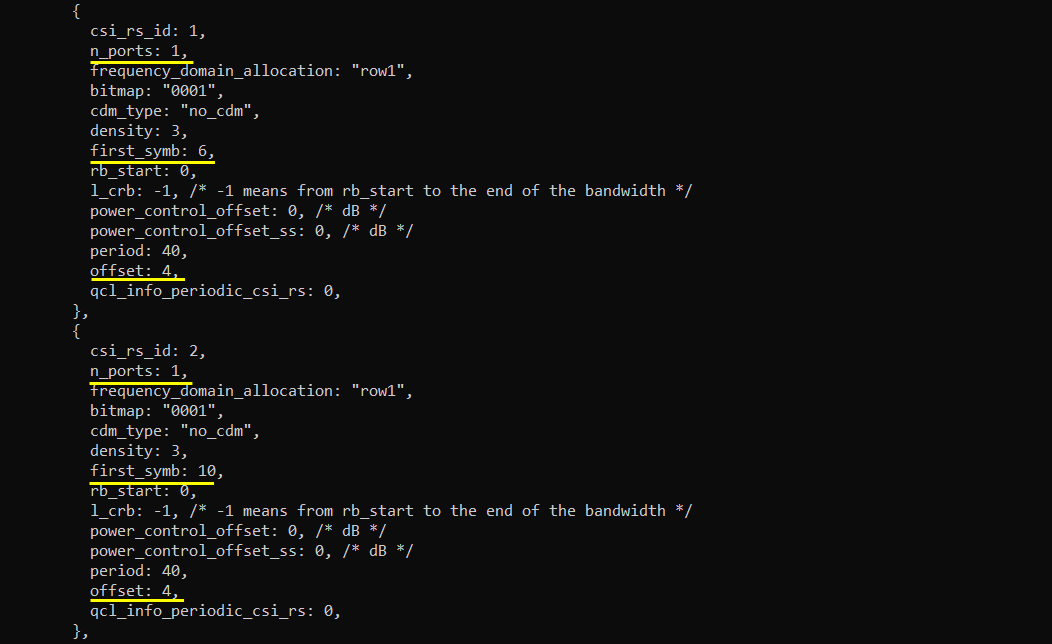
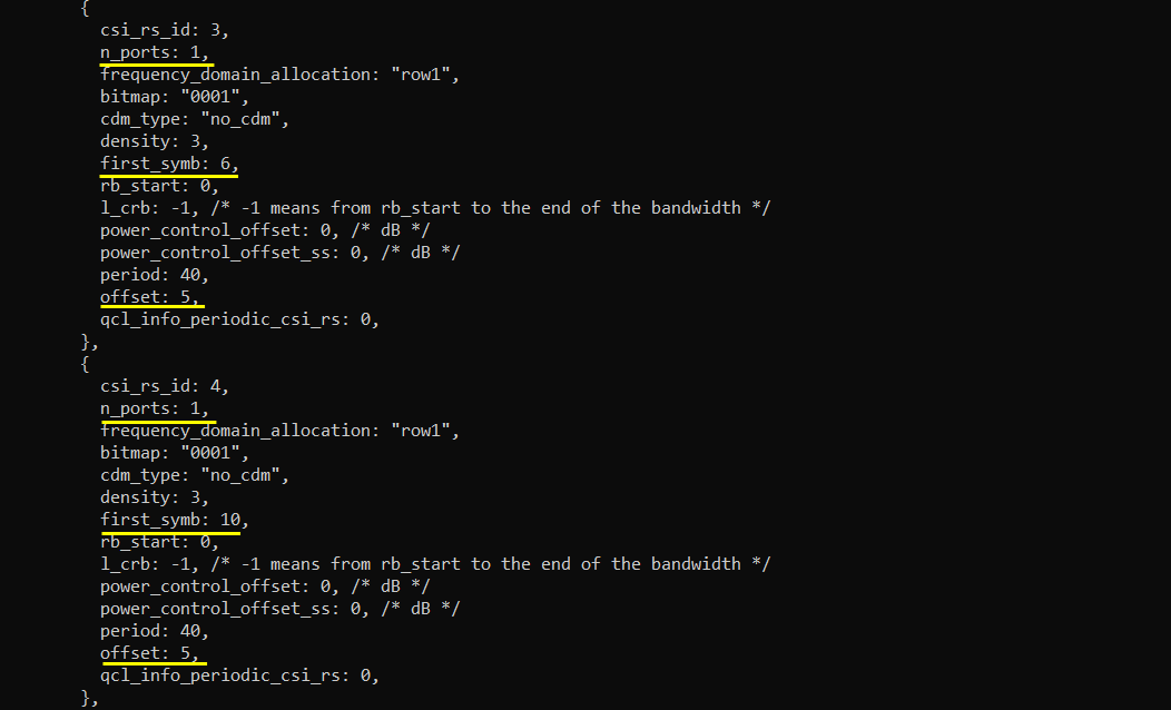
Followings are configurations for csi-rs. Just looking at the numbers would not make much sense. Check out the resource allocation diagram above again and check out the symbol number (OFDM symbol number) and offset (slot) in this configuration and compare them with the diagram shown above.
The parameters to be noted in this example are as follows : (NOTE : the detailed meaning of each of these parameter in terms of 3GPP, check out this note)
- frequency_domain_allocation, cdm_type : the configuration for csi_rs_id 0 is for CSI report and csi_rs_id 1,2,3,4 is to configure TRS.
- n_ports : this is set to be same as the number of DL Antenna for CSI report and set to 1 for TRS
- first_symb, offset : set these in such a way that does not overlap each other and set to meet TRS requirement if they are for TRS.
This is the configuration for interference measurement. symbol_location and offset are configured not to collide with SSB and all other settings are set to be same as in the original sample configuration file.

This is for blank resource elements configuration within PDSCH RB. Set first_symb and offset so that it does not collide with the SSB burst.

Perform Test
Check out the cell phy configuration and see if overall configuration is set as intended

Power on UE and wait until the initial attach is complete and some phy data goes through

Log Analysis
This is just for showing the association between the configuration shown above and IE (Information Elements) in RRC.
You can confirm on ssb position with ssb-PositionInBurst IE in SIB1. Check out if this is properly set as you configured in the configuration file.
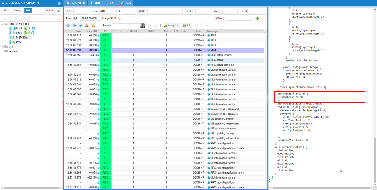
Now check out all the elements related to CSI reference signal and make it sure that they are not colliding with SSB burst in terms of slots and symbols.
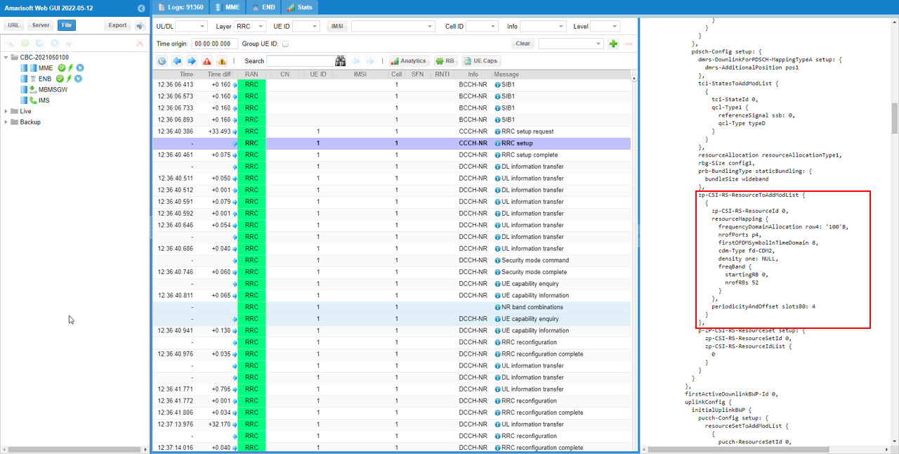
First check out the IE zp-CSI-RS-ResourceToAddModList in RRC Setup. Make it sure that it does not collide with SSB burst by checking periodicityAndOffset IE.
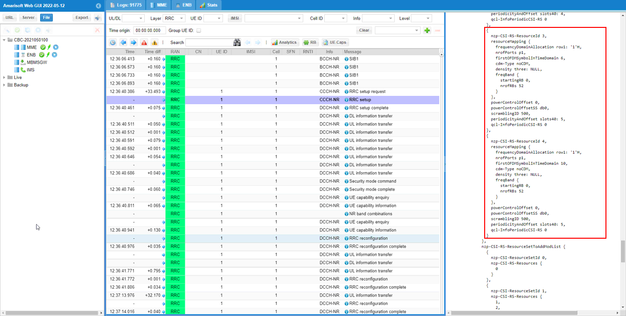
Then check out the IE nzp-CSI-RS-ResourceToAddModList in RRC Setup. Make it sure that noe of the nzp CSI RS does collide with SSB burst by checking firstDMRSSymbolInTimeDomain and periodicityAndOffset IE.
Now check out the IE csi-IM-ResourceToAddModList in RRC Setup. Make it sure that it does not collide with SSB burst by checking csi-IM-ResourceElementPattern and periodicityAndOffset IE.
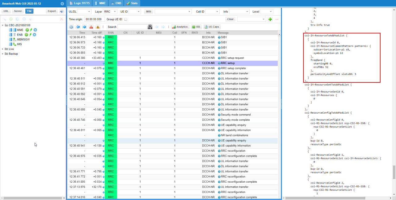 t
t
Just to confirm the CSI report is not interruped by SSB burst configuration, check if all the CSI report is being received at the expected timing.
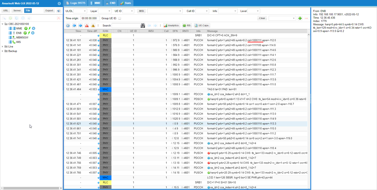
RRC / NAS Signaling
SIB1 (SA)
: This is the SIB1 message sent by gNB to configure NR SA. (
{
message c1: systemInformationBlockType1: {
...
servingCellConfigCommon {
...
ssb-PositionsInBurst {
inOneGroup 'FF'H
},
ssb-PeriodicityServingCell ms20,
|
RrcSetup (SA)
: This is the RrcSetup message sent by gNB to configure NR SA. (
{
message c1: rrcSetup: {
rrc-TransactionIdentifier 0,
...
spCellConfig {
spCellConfigDedicated {
...
csi-MeasConfig setup: {
nzp-CSI-RS-ResourceToAddModList {
{
nzp-CSI-RS-ResourceId 0,
resourceMapping {
frequencyDomainAllocation other: '100000'B,
nrofPorts p2,
firstOFDMSymbolInTimeDomain 3,
cdm-Type fd-CDM2,
density one: NULL,
freqBand {
startingRB 0,
nrofRBs 52
}
},
powerControlOffset 0,
powerControlOffsetSS db0,
scramblingID 500,
periodicityAndOffset slots80: 4,
qcl-InfoPeriodicCSI-RS 0
},
{
nzp-CSI-RS-ResourceId 1,
resourceMapping {
frequencyDomainAllocation row1: '1'H,
nrofPorts p1,
firstOFDMSymbolInTimeDomain 6,
cdm-Type noCDM,
density three: NULL,
freqBand {
startingRB 0,
nrofRBs 52
}
},
powerControlOffset 0,
powerControlOffsetSS db0,
scramblingID 500,
periodicityAndOffset slots40: 4,
qcl-InfoPeriodicCSI-RS 0
},
{
nzp-CSI-RS-ResourceId 2,
resourceMapping {
frequencyDomainAllocation row1: '1'H,
nrofPorts p1,
firstOFDMSymbolInTimeDomain 10,
cdm-Type noCDM,
density three: NULL,
freqBand {
startingRB 0,
nrofRBs 52
}
},
powerControlOffset 0,
powerControlOffsetSS db0,
scramblingID 500,
periodicityAndOffset slots40: 4,
qcl-InfoPeriodicCSI-RS 0
},
{
nzp-CSI-RS-ResourceId 3,
resourceMapping {
frequencyDomainAllocation row1: '1'H,
nrofPorts p1,
firstOFDMSymbolInTimeDomain 6,
cdm-Type noCDM,
density three: NULL,
freqBand {
startingRB 0,
nrofRBs 52
}
},
powerControlOffset 0,
powerControlOffsetSS db0,
scramblingID 500,
periodicityAndOffset slots40: 5,
qcl-InfoPeriodicCSI-RS 0
},
{
nzp-CSI-RS-ResourceId 4,
resourceMapping {
frequencyDomainAllocation row1: '1'H,
nrofPorts p1,
firstOFDMSymbolInTimeDomain 10,
cdm-Type noCDM,
density three: NULL,
freqBand {
startingRB 0,
nrofRBs 52
}
},
powerControlOffset 0,
powerControlOffsetSS db0,
scramblingID 500,
periodicityAndOffset slots40: 5,
qcl-InfoPeriodicCSI-RS 0
}
},
nzp-CSI-RS-ResourceSetToAddModList {
{
nzp-CSI-ResourceSetId 0,
nzp-CSI-RS-Resources {
0
}
},
{
nzp-CSI-ResourceSetId 1,
nzp-CSI-RS-Resources {
1,
2,
3,
4
},
trs-Info true
}
},
csi-IM-ResourceToAddModList {
{
csi-IM-ResourceId 0,
csi-IM-ResourceElementPattern pattern1: {
subcarrierLocation-p1 s8,
symbolLocation-p1 12
},
freqBand {
startingRB 0,
nrofRBs 52
},
periodicityAndOffset slots80: 5
}
},
csi-IM-ResourceSetToAddModList {
{
csi-IM-ResourceSetId 0,
csi-IM-Resources {
0
}
}
},
csi-ResourceConfigToAddModList {
{
csi-ResourceConfigId 0,
csi-RS-ResourceSetList nzp-CSI-RS-SSB: {
nzp-CSI-RS-ResourceSetList {
0
}
},
bwp-Id 0,
resourceType periodic
},
{
csi-ResourceConfigId 1,
csi-RS-ResourceSetList csi-IM-ResourceSetList: {
0
},
bwp-Id 0,
resourceType periodic
},
{
csi-ResourceConfigId 2,
csi-RS-ResourceSetList nzp-CSI-RS-SSB: {
nzp-CSI-RS-ResourceSetList {
1
}
},
bwp-Id 0,
resourceType periodic
}
},
csi-ReportConfigToAddModList {
{
reportConfigId 0,
resourcesForChannelMeasurement 0,
csi-IM-ResourcesForInterference 1,
reportConfigType periodic: {
reportSlotConfig slots80: 9,
pucch-CSI-ResourceList {
{
uplinkBandwidthPartId 0,
pucch-Resource 13
}
}
},
reportQuantity cri-RI-PMI-CQI: NULL,
reportFreqConfiguration {
cqi-FormatIndicator widebandCQI,
pmi-FormatIndicator widebandPMI
},
timeRestrictionForChannelMeasurements notConfigured,
timeRestrictionForInterferenceMeasurements notConfigured,
codebookConfig {
codebookType type1: {
subType typeI-SinglePanel: {
nrOfAntennaPorts two: {
twoTX-CodebookSubsetRestriction '111111'B
},
typeI-SinglePanel-ri-Restriction '03'H
},
codebookMode 1
}
},
groupBasedBeamReporting disabled: {
},
cqi-Table table2,
subbandSize value1
}
}
},
tag-Id 0
}