
NR SA PUSCH Transform Precoding
The purpose of this tutorial is to show you how to configure and verify PUSCH Transform Precoding. In LTE, we use the different waveform for DL and UL by default in which OFDMA is for DL and SC-FDMA(Single Carrier-FDMA) is used for UL. However in NR, we use the same type of waveform OFDM for both DL and UL in most of the default configuration. The reason why we use SC-FDMA in LTE UL is to decrease PAPR (Peak to Average Power Ratio). It implies that UL PAPR would be larger in NR default configuration comparing to LTE UL. For some specific case where low PAPR is necessary in NR, NR support a specific parameter to use SC-FDMA for UL and it is called 'Transform Precoding'. You may think of Transform Precoding as another name for SC-FDMA. There are two stages of applying the Transform Precoding in NR as listed below.
- Apply Transform Precoding only for msg3. You can configure this in SIB1
- Apply Transform Precoding for all other UL except msg3. You can configure this in RRCSetup or RRCReconfiguration.
You can enable both of them or enable only one of the options as you like.
Table of Contents
Introduction
PUSCH (Physical Uplink Shared Channel) Transform Precoding is a key technique in the 5G New Radio (NR) air interface, designed to optimize uplink transmission characteristics, particularly in scenarios demanding low Peak-to-Average Power Ratio (PAPR). In legacy LTE systems, OFDMA (Orthogonal Frequency Division Multiple Access) is employed in the downlink, while SC-FDMA (Single Carrier Frequency Division Multiple Access) is used in the uplink to address the high PAPR challenge, which is critical for power-limited User Equipment (UE). With 5G NR, OFDM (Orthogonal Frequency Division Multiplexing) is adopted for both downlink and uplink by default, providing increased flexibility, spectral efficiency, and simplified transceiver design. However, OFDM inherently exhibits higher PAPR, which can be detrimental for uplink transmissions—particularly for battery-powered devices. To address this, NR introduces Transform Precoding as an optional feature that effectively reintroduces SC-FDMA-like characteristics into the uplink waveform by applying a Discrete Fourier Transform (DFT) prior to subcarrier mapping. This architectural option allows NR to strike a balance between flexibility and power efficiency, enabling operators and device manufacturers to tailor uplink performance to specific scenarios, such as coverage enhancement or IoT applications. Transform Precoding can be selectively enabled at different stages—such as for initial random access (msg3) or for all subsequent uplink transmissions—via parameters configured in SIB1 or RRC signaling. Its significance lies in providing a standards-compliant method to lower PAPR, ensuring robust uplink performance, extending UE battery life, and supporting diverse deployment requirements within the broader 5G ecosystem.
-
Context of PUSCH Transform Precoding in 5G NR
- 5G NR adopts OFDM for both uplink and downlink by default, differing from LTE's use of SC-FDMA in the uplink to reduce PAPR.
- High PAPR in uplink can negatively impact UE battery life and coverage, especially for power-constrained devices.
- Transform Precoding enables a DFT operation prior to subcarrier mapping, emulating SC-FDMA behavior and reducing PAPR.
- The feature can be configured at various protocol stages, including initial access (msg3) and subsequent uplink transmissions.
-
Relevance and Importance of the Tutorial Topic
- Understanding and configuring Transform Precoding is essential for optimizing uplink performance in scenarios where low PAPR is critical.
- The tutorial addresses practical steps for parameter configuration and verification, which are vital for network engineers, system integrators, and device developers.
- Proper configuration impacts device battery longevity, uplink coverage, and overall network efficiency.
-
Learning Outcomes
- Gain a clear understanding of Transform Precoding’s role and benefits in 5G NR uplink transmissions.
- Acquire practical knowledge of how to configure Transform Precoding for different uplink scenarios.
- Learn to verify the correct application of Transform Precoding through relevant configuration parameters.
- Be able to assess when and why to enable Transform Precoding based on deployment needs.
-
Prerequisite Knowledge or Skills
- Familiarity with fundamental wireless communication concepts, especially OFDM and SC-FDMA.
- Basic understanding of LTE and 5G NR protocol architecture and signaling procedures.
- Experience with network configuration, radio resource management, and 3GPP standards is beneficial.
Summary of the Tutorial
This tutorial demonstrates the procedure for testing transform precoding (SC-FDMA) enabled for both Msg3 and subsequent PUSCH transmissions in a 5G NR Standalone (SA) environment using Amarisoft’s UEsim and Callbox (gNB simulator).
-
Test Setup:
- The test configuration involves Amarisoft UEsim as the UE and Callbox as the gNB, connected as depicted in the referenced diagram.
-
Key Configuration Parameters:
- tf_precoding: Enables transform precoding for all PUSCH transmissions after Msg3.
- msg3_tf_precoding: Enables transform precoding specifically for Msg3.
-
Test 1: Transform-Precoding enabled for both Msg3 and PUSCH afterwards
-
Configuration Steps:
- Ensure proper alignment between UEsim and Callbox configuration files. The tutorial uses default configurations (ue.default.cfg and enb.default.cfg) without modification.
- For UEsim, use ue-nr-sa.cfg as-is.
- For the Callbox (gNB), use gnb-sa-tf-precode.cfg (a copy of gnb-sa.cfg).
- The test operates in TDD mode with NR_TDD_CONFIG 2. SRS is disabled for simplicity (USE_SRS 0).
- Band n78 with 30 kHz subcarrier spacing is used, but any band/frequency can be selected.
- msg3_tf_precoding and tf_precoding are both set to true to enable transform precoding for Msg3 and all PUSCH.
- Ensure UE bandwidth and subcarrier spacing in UEsim (BANDWIDTH 20, band:78, subcarrier_spacing:30) match gNB settings.
-
Performing the Test:
- Validate Callbox (gNB) configuration using 'cell phy' and 'cell' commands.
- Power on the UE on UEsim after confirming gNB configuration.
- Confirm successful call setup using the 't' command.
-
Log Analysis:
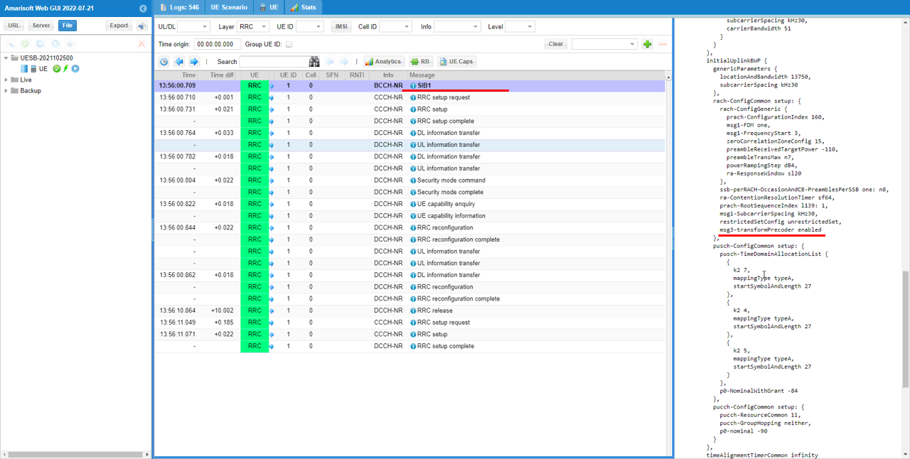
- Confirm msg3 transform precoding is enabled by inspecting the msg3-transformPrecoder information element (IE) in SIB1.
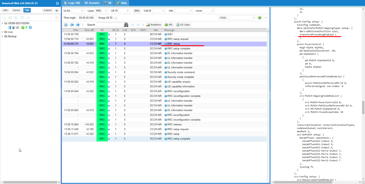
- Verify transform precoding for PUSCH after Msg3 by checking the transformPrecodingEnabled flag in the RRC Setup message.
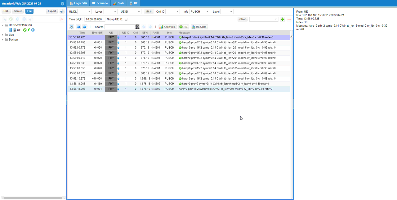
- Ensure all PUSCH transmissions are properly received and decoded by the gNB. Note that PUSCH logs do not directly indicate transform precoding status.
-
Configuration Steps:
The methodology focuses on aligning UE and gNB configurations, enabling and verifying transform precoding features for initial and subsequent uplink transmissions, and confirming correct operation through configuration checks and log analysis.
Test Setup
Setup A
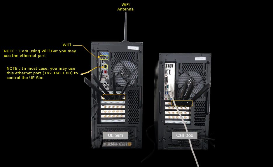
Test setup for this tutorial is as shown below.
The UE Sim and the Call Box are connected through a single SDR port pair, marked on the card row at the back of each box, so one RF cable carries both the downlink and the uplink of the cell under test. Only one cell is used in this tutorial, so no further SDR port is cabled.
I control the UE Sim over WiFi here, but you may use the ethernet port just below the WiFi module instead. In most cases that ethernet port, at 192.168.1.80, is the one you use to reach the UE Sim.
Key Configuration Parameters
Followings are important configuration parameters for this tutorial. You may click on the items for the descriptions from Amarisoft documents.
Test 1 : Transform-Precoding enabled for both Msg3 and PUSCH afterwards
In this test I will show you how to apply transform precoding (SC-FDMA) to Msg3 and all the PUSCH after the msg3.
Configuration
An important thing in using UE sim is to do proper matching between UE sim configuration and Call box configuration In this tutorial, I used the ue.default.cfg and and enb.default.cfg without any change
If you use other Network (e.g, other network simulator or real network), you have to make it sure to configure UE sim according to the settings on network side
I used ue-nr-sa.cfg. as it is
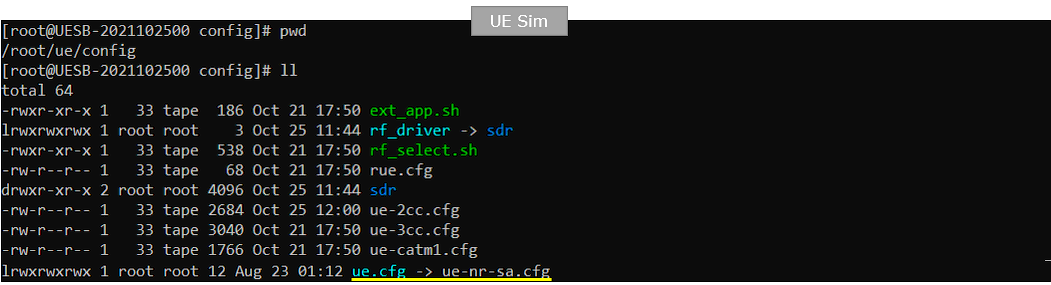
I used gnb-sa-tf-precode.cfg which is copied from gnb-sa.cfg.
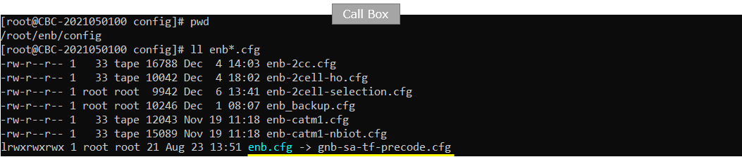
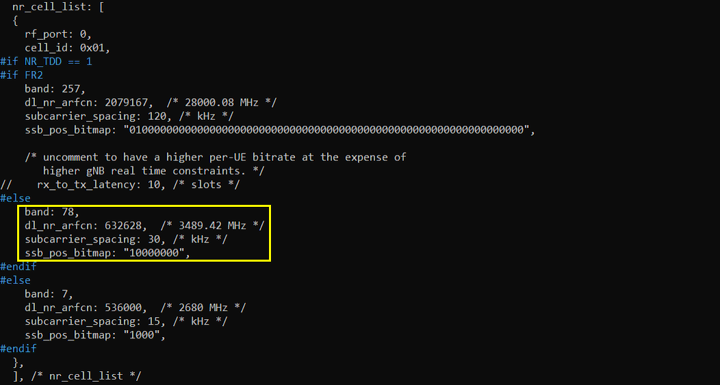
The configuration in gnb-sa-tf-precode.cfg (Callbox) is set as follows. In this test, TDD is used and one of the default TDD config (NR_TDD_CONFIG 2) is applied. And SRS is disabled (USE_SRS 0) for simplicity.
NR_TDD is set to 1 and FR2 is set to 0, so the cell runs as an FR1 TDD cell and the FR1 side of the #if FR2 block is the one that applies. That side gives NR_TDD_CONFIG 2 and NR_BANDWIDTH 20. The FR2 side above it, with UDC_TYPE 1, NR_TDD_CONFIG 10 and NR_BANDWIDTH 100, is not used in this test.
N_ANTENNA_DL is 2 and N_ANTENNA_UL is 1, so the downlink can carry two layers while the uplink stays single layer. USE_SRS is what would enable periodic SRS on the N_ANTENNA_UL ports, and with N_ANTENNA_UL of 2 or more it would also turn on uplink SU-MIMO, so leaving it at 0 keeps the uplink to a plain single stream PUSCH and keeps this test focused on the waveform. NR_LONG_PUCCH_FORMAT is 2.
If you want to run the same test on a wider cell, change NR_BANDWIDTH in the FR1 branch and set the matching bandwidth on the UEsim side. Transform precoding does not depend on any of these defines, so you can leave them as they are and still get the same result.
It doesn't matter whatever band and frequency is used for transform precoding. In this test, n78 (band :78) with SCS 30 Khz (subcarrier_spacing 30) is used.
The cell sits in nr_cell_list with rf_port 0 and cell_id 0x01. The carrier itself is picked by the nested #if NR_TDD == 1 and #if FR2 test, and with NR_TDD 1 and FR2 0 the branch that applies is the one carrying band 78, dl_nr_arfcn 632628 which is 3489.42 MHz, subcarrier_spacing 30 and ssb_pos_bitmap "10000000".
The other two branches are there only so that the same file can be reused for other setups. The FR2 branch with band 257 at dl_nr_arfcn 2079167 and subcarrier_spacing 120, and the FDD branch with band 7 at dl_nr_arfcn 536000 and subcarrier_spacing 15, are not compiled in this test.
To run this test on another carrier, change band, dl_nr_arfcn and subcarrier_spacing in that FR1 TDD branch and make the same change on the UEsim side. The commented rx_to_tx_latency line belongs to the FR2 branch and is left untouched.
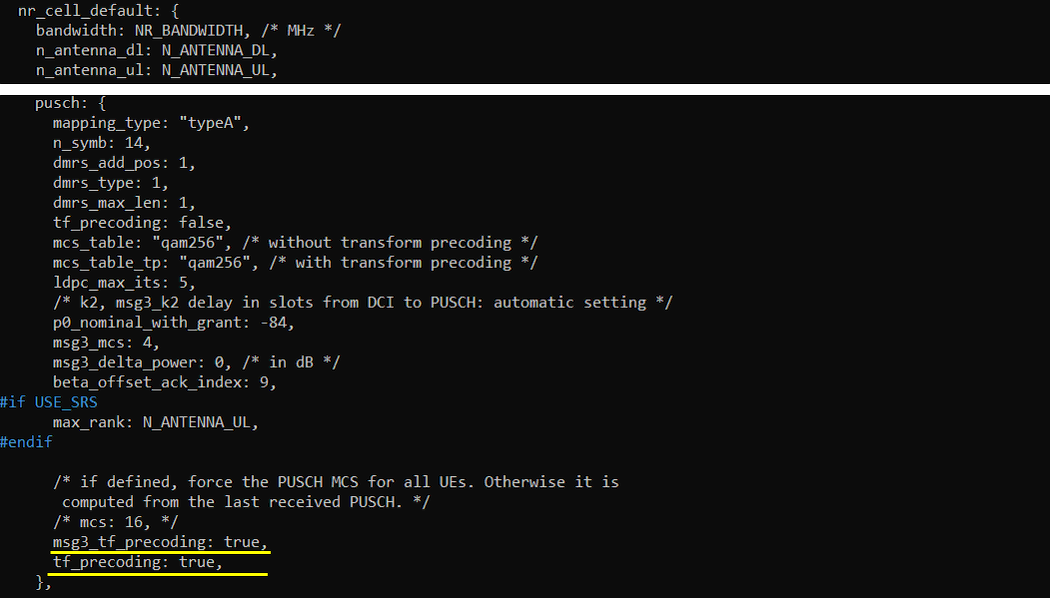
These are the main configuration parameter for transform preconding. Transform Precoding is applied to msg3 by setting msg3_tf_precoding to true and applied to all the PUSCH by setting tf_precoding to true.
Both lines are added at the very end of the pusch block of nr_cell_default, after the commented mcs line, and they are the last assignment in that block. The block still carries the stock tf_precoding: false further up with the rest of the defaults, and the two lines at the end are the ones in effect for this test. msg3_tf_precoding defaults to whatever tf_precoding is set to, so setting tf_precoding alone would already have turned msg3 on, but I set both of them explicitly so that each of the two stages is visible in the file.
The same block decides which MCS table the uplink uses. mcs_table selects the table for the case where transform precoding is disabled and mcs_table_tp selects the table used once it is enabled, and both are set to "qam256" here, so switching transform precoding on does not change the modulation range available to the uplink. The remaining PUSCH settings are the defaults of this cell : mapping_type "typeA", n_symb 14, dmrs_add_pos 1, dmrs_type 1, dmrs_max_len 1, ldpc_max_its 5, p0_nominal_with_grant -84, msg3_mcs 4, msg3_delta_power 0 and beta_offset_ack_index 9. The max_rank line sits inside #if USE_SRS and is not compiled here because USE_SRS is 0.
If you want transform precoding on msg3 only, set msg3_tf_precoding to true and leave tf_precoding at false. For the opposite case, set tf_precoding to true and set msg3_tf_precoding to false explicitly, because leaving it out would make it follow tf_precoding and enable msg3 as well.
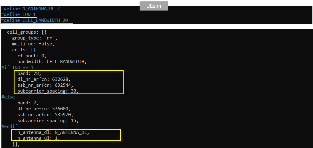
The configuration in ue-nr-sa.cfg (UEsim) is set as follows. TDD is used for UEsim to be aligned to Callbox (gNB) configuration. BANDWIDTH 20 and band :78, subcarrier_spacing:30 are configured to get aligned to gNB configuration.
The three defines at the top of the file drive the whole cell entry. TDD 1 selects the #if TDD == 1 branch, which gives band 78, dl_nr_arfcn 632628, ssb_nr_arfcn 632544 and subcarrier_spacing 30, and the #else branch with band 7 at dl_nr_arfcn 536000 and subcarrier_spacing 15 is not used here. CELL_BANDWIDTH 20 is what the cell entry picks up as bandwidth, and N_ANTENNA_DL 2 is what it picks up as n_antenna_dl. The cell group is declared with group_type "nr", multi_ue false and rf_port 0.
n_antenna_ul is set to 1 so that it matches N_ANTENNA_UL 1 on the Callbox side. ssb_nr_arfcn 632544 is the one value that has no direct counterpart in the gNB file, since the gNB derives its SSB position from ssb_pos_bitmap, and it is worth checking against the SSB ARFCN the gNB reports so that the UE searches where the SSB is actually transmitted.
There is no transform precoding parameter anywhere in the UEsim file, and there does not need to be one. The UE applies transform precoding because the gNB tells it to, through msg3-transformPrecoder in SIB1 and transformPrecodingEnabled in RRC Setup, so the UEsim side only has to be aligned on band, ARFCN, bandwidth, subcarrier spacing and antenna count.
Perform the Test
check if callbox confgiuration (gNB configuration) is properly set as you intended by the command 'cell phy' and 'cell'.
'cell phy' prints one row for cell 0x001 on gNB_ID 0x12345 and PLMN 00101, and it splits into a global part, a downlink part, an uplink part and an SSB part. The global part reads RAT NR, band n78 and BW 20. The downlink is on ARFCN 632628 with 2 antennas, 2 layers, SCS 30 and QAM 256, the uplink is on the same ARFCN 632628 with 1 antenna, 1 layer, SCS 30 and QAM 256, and the SSB is on ARFCN 632544 with SCS 30. The uplink QAM column of 256 is the mcs_table_tp setting, which is the table that applies once transform precoding is on.
'cell' prints the cell level parameters : TAC 0x000064, dl_arfcn 632628, pci 500, prach_seq 1, dl_gain 0.0, ul_dis N and plmn 00101. Neither command prints anything about transform precoding, so at this point you are only confirming that the carrier, the numerology and the antenna counts came up as configured. The confirmation of transform precoding itself comes from SIB1 and RRC Setup in the log.

If gNB configuration is done as you desire, power on UE on UEsim.
power_on is typed at the (ue) prompt of the UEsim console. Before that I set the log file with 'log file.rotate=250M,file.path=/var/log/lte/', so that the trace of this run is kept on disk and can be opened later in the WebGUI.
The RF0 line printed above the prompt is the one to read back after the UEsim starts. It reports the sample rate, the downlink and uplink frequency, the band and the number of downlink and uplink antennas that the UEsim actually brought up, and those have to be the ones the gNB is running on. If they are not, the UE will never find the SSB and no PRACH will reach the Callbox.

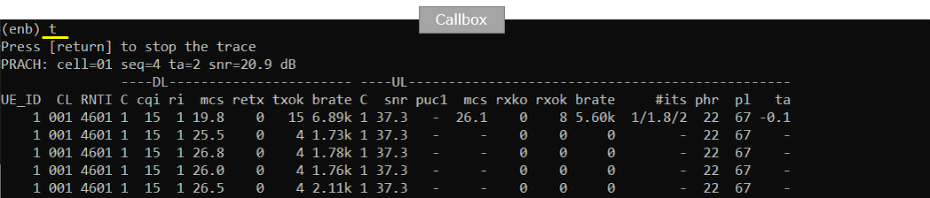
Make it sure that call setup is properly established using 't' command.
The first thing 't' prints is the PRACH line, here cell=01 with seq=4, ta=2 and snr=20.9 dB, which tells you the preamble was detected and the timing advance was resolved. After that the trace runs one row per second for UE_ID 1 on cell 001 with RNTI 4601, which is the UE that completed the random access.
On the downlink side cqi stays at 15 and ri at 1, mcs runs between 19.8 and 26.8 and retx stays at 0. On the uplink side snr is 37.3 dB, the first row carries mcs 26.1 with rxok 8, rxko 0 and brate 5.60k, phr 22, pl 67 and ta -0.1. The rows after it show no uplink counters because the signalling is over and there is no uplink traffic left to send. What matters here is that the uplink rows have rxko at 0, meaning the transform precoded PUSCH is being decoded without failure, and that a high uplink mcs is being reached.
't' does not report transform precoding either, so use it only to confirm that the call is up and that the uplink is healthy before moving to the log.
Log Analysis
You can confirm that msg3 transform precoding is enabled by checking out msg3-transformPrecoder IE in SIB1.
Set Layer to RRC and the SIB1 on BCCH-NR is the first entry of the call, at 13:56:00.709 in this run, ahead of the RRC setup request that follows it 1 ms later. Open it and scroll the decoded message down to servingCellConfigCommon, uplinkConfigCommon, initialUplinkBWP.
msg3-transformPrecoder enabled is the last item of rach-ConfigCommon, next to prach-ConfigurationIndex 160, msg1-FDM one, msg1-FrequencyStart 3, prach-RootSequenceIndex l139: 1, msg1-SubcarrierSpacing kHz30 and restrictedSetConfig unrestrictedSet. That placement is what makes it usable : it is broadcast with the rest of the random access parameters, so the UE has it before it ever sends msg3. The initialUplinkBWP that carries it is locationAndBandwidth 13750 with subcarrierSpacing kHz30.
The IE only appears when msg3_tf_precoding is true. Set it to false and SIB1 carries no msg3-transformPrecoder at all, and msg3 goes out as ordinary OFDM even if the PUSCH after it is transform precoded.
Transform Precoding for PUSCH after msg3 can be confirmed by checking out transformPrecodingEnabled in RRC Setup. If transformPrecodingEnabled exists, it indicates transform precoding is enabled.
The RRC setup on CCCH-NR is at 13:56:00.731 here, 21 ms after the RRC setup request. In the decoded message the place to look is spCellConfigDedicated, uplinkConfig, initialUplinkBWP, pusch-Config, and inside it dmrs-UplinkForPUSCH-MappingTypeA. transformPrecodingEnabled sits there beside dmrs-AdditionalPosition pos1, and it is an empty container in this run because none of the optional DMRS sequence options are configured. n_id_rs, group_hopping and sequence_hopping are all left at their defaults in the gNB configuration, so there is nothing to put inside it.
The rest of pusch-Config in this message is txConfig codebook, resourceAllocation resourceAllocationType1, codebookSubset nonCoherent and maxRank 1. resourceAllocationType1 is not incidental here : transform precoding cannot be used together with resource allocation type 0, so a cell configured with ra_type type0 would not be able to run this test.
The mapping type matters as well. transformPrecodingEnabled is carried per DMRS mapping type, and here it is present under mapping type A, which is the mapping_type set for PUSCH in the gNB configuration.
Make it sure that all the PUSCH are properly received and decoded by gNB. PUSCH log print itself does not print any specific information about transform precoding.
Set Layer to PHY and Info to PUSCH and only the PUSCH entries are left. Each line carries harq, the allocated PRBs, symb=0:14, and then the transport block as tb_len, mod, rv_idx, cr and retx. The first one at 13:56:00.725 is the small grant, prb=2 with tb_len=9, mod=2 and cr=0.30, and the ones after it are the larger allocations, prb=15:2 or prb=47:2 with tb_len=201 at mod=6 and cr=0.93, and a few with tb_len=8 at mod=8 and cr=0.69.
Every line has rv_idx=0 and retx=0, so no transport block needed a second attempt. The mod values of 2, 6 and 8 are QPSK, 64QAM and 256QAM, taken from the qam256 table that mcs_table_tp selects for the transform precoded case. From 13:56:11.065 the RNTI changes from 4601 to 4602, which is the second RRC setup after the RRC release at 13:56:10.864.
None of these fields names transform precoding, and there is no separate PHY entry for it either. This part of the log is where you confirm that the uplink is working under the setting, not where you confirm the setting itself.
RRC / NAS Signaling
SIB1 (SA)
: This is the SIB1 message sent by gNB to enable transform precoding for msg1. (
{
message c1: systemInformationBlockType1: {
cellSelectionInfo {
...
},
cellAccessRelatedInfo {
...
},
connEstFailureControl {
...
},
servingCellConfigCommon {
downlinkConfigCommon {
frequencyInfoDL {
...
},
initialDownlinkBWP {
genericParameters {
locationAndBandwidth 13750,
subcarrierSpacing kHz30
},
pdcch-ConfigCommon setup: {
...
},
pdsch-ConfigCommon setup: {
...
}
},
bcch-Config {
...
},
pcch-Config {
...
}
},
uplinkConfigCommon {
frequencyInfoUL {
scs-SpecificCarrierList {
{
offsetToCarrier 0,
subcarrierSpacing kHz30,
carrierBandwidth 51
}
}
},
initialUplinkBWP {
genericParameters {
locationAndBandwidth 13750,
subcarrierSpacing kHz30
},
rach-ConfigCommon setup: {
rach-ConfigGeneric {
prach-ConfigurationIndex 160,
msg1-FDM one,
msg1-FrequencyStart 3,
zeroCorrelationZoneConfig 15,
preambleReceivedTargetPower -110,
preambleTransMax n7,
powerRampingStep dB4,
ra-ResponseWindow sl20
},
ssb-perRACH-OccasionAndCB-PreamblesPerSSB one: n8,
ra-ContentionResolutionTimer sf64,
prach-RootSequenceIndex l139: 1,
msg1-SubcarrierSpacing kHz30,
restrictedSetConfig unrestrictedSet,
msg3-transformPrecoder enabled
},
pusch-ConfigCommon setup: {
...
},
pucch-ConfigCommon setup: {
...
}
},
timeAlignmentTimerCommon infinity
},
ssb-PositionsInBurst {
...
},
ssb-PeriodicityServingCell ms20,
tdd-UL-DL-ConfigurationCommon {
...
},
...
},
ue-TimersAndConstants {
...
RrcSetup (SA)
: This is the RrcSetup message sent by gNB to enable transform precoding for PUSCH after msg1. (
{
message c1: rrcSetup: {
rrc-TransactionIdentifier 0,
criticalExtensions rrcSetup: {
radioBearerConfig {
...
},
masterCellGroup {
...
},
physicalCellGroupConfig {
...
},
spCellConfig {
spCellConfigDedicated {
initialDownlinkBWP {
pdcch-Config setup: {
...
},
pdsch-Config setup: {
...
},
firstActiveDownlinkBWP-Id 0,
uplinkConfig {
initialUplinkBWP {
pucch-Config setup: {
...
},
pusch-Config setup: {
txConfig codebook,
dmrs-UplinkForPUSCH-MappingTypeA setup: {
dmrs-AdditionalPosition pos1,
transformPrecodingEnabled {
}
},
pusch-PowerControl {
...
},
resourceAllocation resourceAllocationType1,
codebookSubset nonCoherent,
maxRank 1,
uci-OnPUSCH setup: {
...
}
},
srs-Config setup: {
...
}
},
firstActiveUplinkBWP-Id 0,
pusch-ServingCellConfig setup: {
}
},
pdcch-ServingCellConfig setup: {
},
pdsch-ServingCellConfig setup: {
...
},
csi-MeasConfig setup: {
...