NR SA PTRS - PDSCH
The purpose of this tutorial is to show you how to configure PTRS for PDSCH . PTRS stands for Phase Tracking Reference Signal is a kind of reference signal that is used for adjusting Phase Shift in harsh channel condition.
- RRC parameter configured in DMRS-DownlinkConfig : This determines deterimine time domain and frequency domain positions of the reference signal (details)
Table of Contents
Introduction
Phase Tracking Reference Signal (PTRS) is a crucial feature in 5G NR (New Radio) systems, specifically designed to enhance the robustness and reliability of downlink data transmission over the Physical Downlink Shared Channel (PDSCH) under challenging radio conditions. PTRS provides the means for user equipment (UE) to accurately track and compensate for phase noise and other impairments caused by high-frequency oscillators, Doppler effects, or rapid signal fading. Architecturally, PTRS is embedded within the PDSCH resource grid, with its configuration governed via RRC (Radio Resource Control) parameters, particularly within the DMRS-DownlinkConfig structure. By optimizing the time and frequency placement of these reference signals, PTRS enables the receiver to perform precise phase correction, which is essential for maintaining low error rates and ensuring high throughput in environments susceptible to phase instability. The configuration and efficient use of PTRS are significant for operators and engineers aiming to deliver high-capacity, low-latency services in scenarios such as massive MIMO deployments or mmWave communications, where phase noise and interference are more pronounced. As a result, understanding how to configure PTRS within the PDSCH framework is vital for maximizing system performance, interoperability, and user experience in advanced 5G networks.
-
Context of PTRS in 5G NR
- PTRS is a specialized reference signal introduced in 5G to address the challenges of phase noise, particularly in high-frequency bands (e.g., mmWave).
- It operates alongside other reference signals, such as DMRS (Demodulation Reference Signal), but serves the specific purpose of fine phase tracking.
- Integration of PTRS into PDSCH ensures robust demodulation and error correction in dynamic radio environments.
-
Relevance and Importance of This Tutorial
- Configuring PTRS optimally is essential for reliable downlink communication, especially in scenarios with significant phase distortion.
- This tutorial demystifies the process of configuring PTRS in the context of PDSCH and explains the role of RRC parameters, such as those found in DMRS-DownlinkConfig.
- It provides a practical guide for network engineers, system integrators, and researchers working on advanced 5G deployments.
-
Learning Outcomes
- Understand the architectural role and technical principles of PTRS in 5G downlink transmission.
- Gain practical knowledge of how PTRS is configured via RRC signaling, focusing on its time and frequency domain mappings.
- Acquire the skills to analyze and optimize PTRS parameters to improve system robustness and throughput.
-
Prerequisite Knowledge
- Familiarity with 5G NR architecture and physical layer concepts, especially PDSCH and reference signals.
- Basic understanding of RRC signaling and parameter configuration in 5G systems.
- Some experience with wireless communication systems and signal processing is beneficial but not mandatory.
Summary of the Tutorial
This tutorial outlines the setup and execution of a low-layer test focusing on the configuration and verification of PTRS (Phase Tracking Reference Signal) for SISO in a 5G NR Standalone (SA) environment. The procedure emphasizes configuration steps, test execution, and log analysis without reliance on advanced IP layer settings.
-
Test Setup:
- Utilize the provided SIM card as delivered with the system.
- Refer to the Configuration Guide if further configuration changes are required.
- Low-layer setup involving a gNB (callbox) and UEsim is depicted in the associated diagram.
-
Key Configuration Parameters:
- Focus on configuring the ptrs object, which includes parameters such as frequency_density, time_density, epre_ratio, and resource_element_offset.
-
Test 1: Basic PTRS Configuration for SISO
-
Configuration Steps:
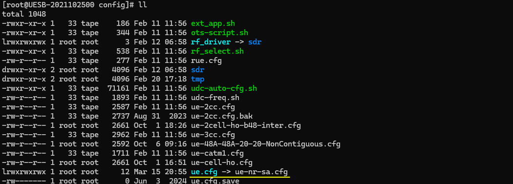
- Start by copying and modifying gnb-sa.cfg to create gnb-sa-pdsch-ptrs.cfg.
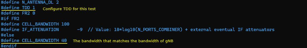
- Set N_ANTENNA_DL to 1 in the configuration to establish SISO operation.
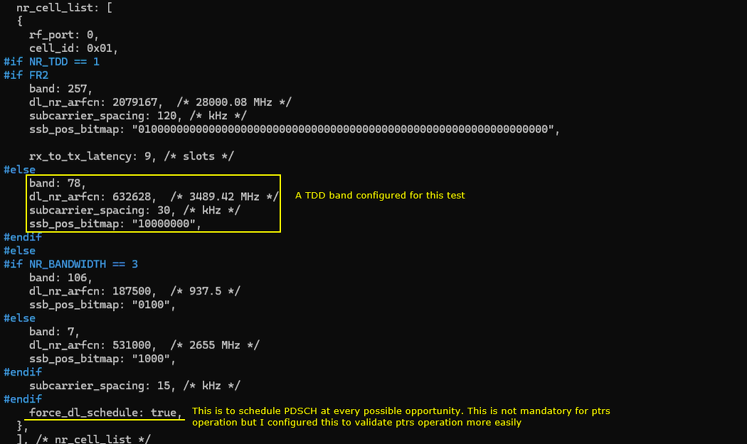
- In the nr_cell_list, enable force_dl_schedule : true to ensure PDSCH is scheduled at every opportunity, facilitating PTRS verification.
- Configure the ptrs object within the PDSCH section, specifying the required density and offset parameters for PTRS.
- For UEsim, use the default ue-nr-sa.cfg configuration file without modifications.
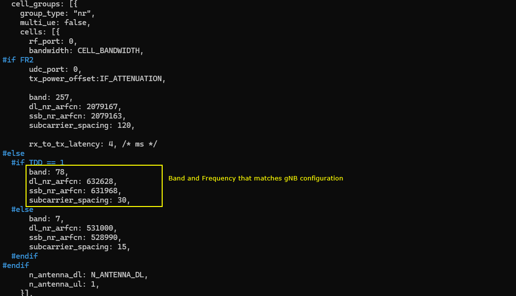
- Ensure TDD and CELL_BANDWIDTH, as well as band, frequency (dl_nr_arfcn, ssb_nr_arfcn), and subcarrier_spacing settings match between gNB and UEsim.
-
Test Execution:
- Start the test system and verify the number of physical antennas using the cell phy command.
- Establish a call and verify call connectivity using the t command.
-
Log Analysis:
- Review RRC logs to confirm PTRS configuration as intended, particularly the phaseTrackingRS field in RRC Reconfiguration.
- Check PDSCH logs to determine if PTRS is activated (indicated by ptrs=1).
-
Configuration Steps:
The methodology focuses on a step-by-step workflow: preparing configurations, aligning parameters between gNB and UE, running the test, and analyzing logs for correct PTRS operation. The entire process is designed for straightforward validation of PTRS in a SISO scenario, with key configuration parameters highlighted for clarity.
Test Setup
Test setup for this tutorial is as shown below. This is just for low layer testing, you may not need any complicated IP layer setup.
- SIM Card used in this tutorial is the one delivered with the system as it is.
- If you want to change the configuration, The tutorial Configuration Guide would help

Key Configuration Parameters
Followings are important configuration parameters for this tutorial. You may click on the items for the descriptions from Amarisoft documents.
Test 1 : Basic Configuration
The purpose of this test is to provide an example of how to configure a basic PTRS configuration for SISO. I used SISO just because it is the default configuration of gnb-sa.cfg. MIMO configuration does not directly affect the operation of PTRS.
Configuration
I have used gnb-sa-pdsch-ptrs.cfg which is copied and modified from gnb-sa.cfg

I am using the default mme, ims config as shown below.

On UEsim side, I am using the default configuration ue-nr-sa.cfg without any modification (
In gnb-sa-pdsch-ptrs.cfg , it is configured as follows. I set N_ANTENNA_DL to 1 meaning that I want to use SISO. You can use any kind of configuration as you like.

I am testing this in n78, but it doesn't matter whatever band you use. The special configuration that I did in nr_cell_list is force_dl_schedule : true. This is not mandatory configuration, it is only for easy verification. Since Downlink PTRS is transmitted in association with PDSCH, which mean that we need to schedule PDSCH to check out the downlink PTRS. force_dl_schedule : true is to schedule PDSCH at every possible opportunities.
Following is the main configuration for this test which are to configure ptrs. As shown here, the parameter is ptrs object. Within the ptrs object, you can configure the detailed property of the ptrs. For the details for the meaning of frequency_density (Frequency Density), time_density (Time Density) and resource_element_offset (Resource Element Offset), you may refer to this note.

For UEsim configuration, the default configuration file ue-nr-sa.cfg is used without any modification (
Configure TDD and CELL_BANDWIDTH to match the configuration of gNB.
Configure the band, frequency (dl_nr_arfcn, ssb_nr_arfcn) and subcarrier spacing (subcarrier_spacing) to match the configuration of gNB (Callbox)
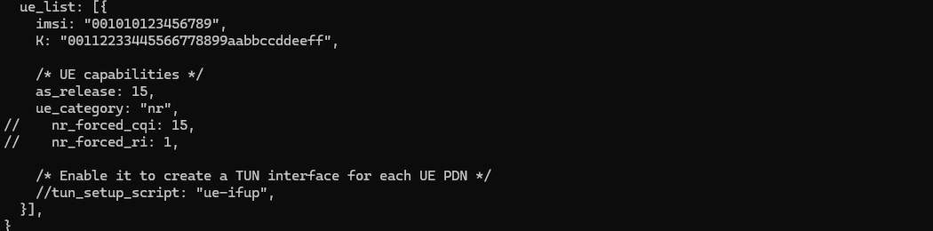
I just used ue_list parameter without any modification.
Perform the Test
First run the test and check on the number of physical antenna using cell phy command.

Then setup a call and make it sure that call connection is OK using t command.

Log Analysis
First check RRC log and see if the configuration is done as you intended.
PTRS is configured by phaseTrackingRS IE in RRC Reconfiguration. You can compare the settings in the configuration file and phaseTrackingRS IE as shown below.

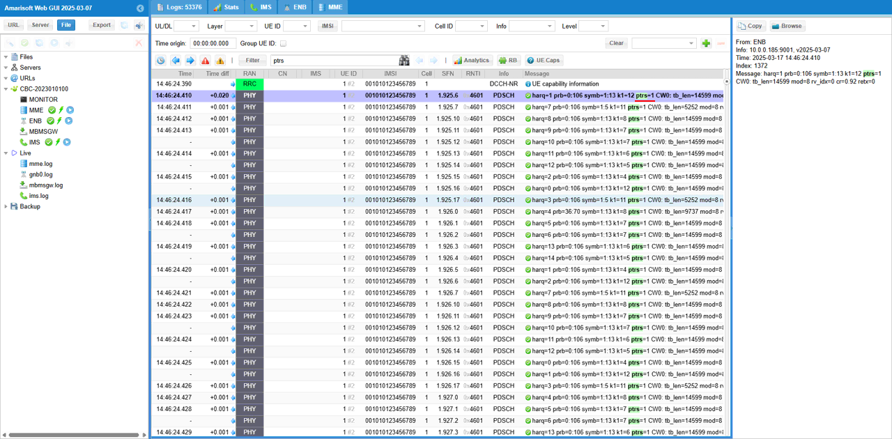
PTRS transmission gets enabled or disabled depending in MCS and the state of PTRS activation is printed in PDSCH log. If the PTRS is activated/transmitted, ptrs=1 is transmitted.
RRC / NAS Signaling
RrcReconfiguration(SA)
: This is the RrcSetup message sent by gNB to configure PDSCH PTRS. (
{
message c1: rrcReconfiguration: {
rrc-TransactionIdentifier 0,
criticalExtensions rrcReconfiguration: {
nonCriticalExtension {
masterCellGroup {
cellGroupId 0,
spCellConfig {
spCellConfigDedicated {
initialDownlinkBWP {
pdsch-Config setup: {
dmrs-DownlinkForPDSCH-MappingTypeA setup: {
dmrs-AdditionalPosition pos0,
phaseTrackingRS setup: {
frequencyDensity {
10,
20
},
timeDensity {
5,
15,
20
},
resourceElementOffset offset10
}
},
resourceAllocation resourceAllocationType1,
rbg-Size config1,
mcs-Table qam256,
prb-BundlingType staticBundling: {
bundleSize wideband
}
}
},
uplinkConfig {
initialUplinkBWP {
pusch-Config setup: {
txConfig codebook,
resourceAllocation resourceAllocationType1,
mcs-Table qam256,
mcs-TableTransformPrecoder qam256,
codebookSubset nonCoherent,
maxRank 1
}
}
},
pdsch-ServingCellConfig setup: {
nrofHARQ-ProcessesForPDSCH n16,
maxMIMO-Layers 1
},
tag-Id 0
}
}
},
dedicatedNAS-MessageList {
'7E024E13893B017E0042010977000BF200F110800101D5916D6554070000F1100000641502010131020101210203005E01BE3408031F19F1031F11F2'H
}
}
}
}
}