
NR SA PDSCH Aggregation
The purpose of this tutorial is to show you how to configure and test PDSCH Aggregation Factor / Repetition. Main user case of this mechanism is to provide chance of more reliable PDSCH reception. Conceptually you may consider this to be similar to PDSCH in LTE IoT application. Overall mechanism of PDSCH Aggrection Factor can be illustrated as below.

Image Source : Sharetechnote
Table of Contents
Introduction
The Physical Downlink Shared Channel (PDSCH) Aggregation Factor and Repetition mechanism is a critical feature within 5G NR (New Radio) networks, designed to enhance the reliability of downlink data transmission under challenging radio conditions. In 5G NR architecture, the PDSCH serves as the primary channel for delivering user data from the gNB (Next Generation NodeB) to the User Equipment (UE). The Aggregation Factor and Repetition mechanism enables the network to transmit identical or redundant PDSCH data blocks over multiple time-frequency resources, effectively increasing the likelihood of successful data decoding at the UE, especially in scenarios characterized by high interference, deep fading, or coverage-limited environments. Mechanistically, this feature draws conceptual parallels to the PDSCH repetition techniques employed in LTE IoT (Internet of Things) applications, where repeated transmissions improve reliability for devices with limited capabilities or in challenging locations. Architecturally, the mechanism is supported by enhancements in the physical layer and scheduling algorithms, allowing dynamic adjustment of the aggregation factor based on real-time link quality and UE capability information. The introduction of this feature, supported by 5G NR releases since early 2023, marks a significant step toward achieving the ultra-reliable low-latency communication (URLLC) objectives of 5G, while also expanding support for massive IoT deployments. By offering configurable levels of repetition and aggregation, network operators can tailor downlink reliability to specific service requirements, thus playing a pivotal role in the broader 5G ecosystem, which demands both high throughput and robust connectivity across diverse use cases.
-
Technology Context
- The PDSCH Aggregation Factor/Repetition is a physical layer enhancement in 5G NR, enabling more robust downlink data delivery by transmitting the same transport block across multiple resources.
- This mechanism is analogous to reliability enhancements found in LTE IoT, but is architected for the advanced scheduling and flexibility of 5G NR.
- It operates within the context of 5G's overall goal to support a wide variety of use cases, from enhanced mobile broadband (eMBB) to URLLC and massive machine-type communications (mMTC).
-
Relevance and Importance
- Enhancing PDSCH reliability is essential for maintaining consistent user experiences, especially at cell edges or in environments with poor radio conditions.
- The Aggregation Factor/Repetition feature is critical for supporting mission-critical applications and IoT devices that require high reliability and/or operate in coverage-challenged scenarios.
- Its configurability allows network operators to balance between spectral efficiency and reliability, aligning with service-level agreements (SLAs) and application needs.
-
Tutorial Outcomes
- Learners will gain a comprehensive understanding of how to configure and test the PDSCH Aggregation Factor/Repetition feature in a 5G NR network environment.
- The tutorial provides practical insights into feature activation, parameter tuning, and validation methodologies to ensure effective deployment.
- Participants will develop the ability to analyze PDSCH performance metrics to assess the impact of aggregation and repetition on downlink reliability.
-
Prerequisite Knowledge and Skills
- Familiarity with 5G NR architecture, especially physical layer concepts such as PDSCH, scheduling, and link adaptation.
- Understanding of radio resource management and basic network configuration procedures.
- Experience with 5G NR test equipment, simulation tools, or network management interfaces is recommended for hands-on exercises.
Summary of the Tutorial
This tutorial provides a detailed procedure for testing PDSCH Aggregation Factor operation in NR SA TDD mode, focusing on configuration, execution, and verification steps.
-
Test Setup:
- The test setup involves a gNB (using Amarisoft Callbox), a UE simulator, and appropriate network configurations. Refer to the included diagram for physical and logical connections.
-
Key Configuration Parameters:
- The essential parameter for this test is aggregation_factor in the pdsch configuration section.
-
Test 1: PDSCH Aggregation - TDD
- Purpose: To validate the PDSCH Aggregation Factor operation in a 5G NR Standalone (SA) TDD scenario.
-
Configuration Steps:
- Use gnb-sa-pdsch-agg.cfg as the gNB configuration, modified from the default sample (gnb-sa.cfg).
- Use default IMS (ims.default.cfg) and MME (mme-ims.cfg) configurations for Callbox.
- Enable detailed logging with phy.rep=1 for PDSCH repetition verification (optional but recommended).
- Set the duplex mode to TDD (NR_TDD=1) and configure the desired TDD pattern using NR_TDD_CONFIG.
- Specify test band (e.g., n78) and subcarrier spacing (e.g., 30 kHz), though any 3GPP-compliant combination may be used.
- Enable PDSCH aggregation by adding the aggregation_factor parameter within the pdsch configuration.
- For UE, use the ue-nr-sa.cfg configuration without modification.
- Ensure UE settings (TDD, band, subcarrier spacing, channel frequency, and SSB frequency) match the Callbox configuration.
- Configure the UE access release (as_release) to 15 and ue_category to "nr".
-
Test Execution Steps:
- Start LTE service (gNB) and run the cell phy and cell commands to initialize the radio cell.
- Power on the UE simulator using the power_on command.
- Confirm UE attachment and check throughput using the 't' command.
-
Log Analysis and Verification:
- Enable the 'Repetition' option in the eNB log property window for enhanced verification.
- After initial attach, check the UE capability information to verify support for PDSCH aggregation (specifically pdsch-RepetitionMultiSlots).
- If supported, confirm that gNB enables PDSCH Aggregation by setting pdsch-AggregationFactor in the PDSCH configuration.
- Validate in the PHY logs that PDSCH aggregation is operational: after PDCCH/DCI 1_1 schedules a PDSCH, observe multiple consecutive PDSCH transmissions with correct repetition and redundancy version indices, without additional scheduling messages.
- Use the WebGUI to visually confirm consecutive PDSCH transmissions (distinct color coding for initial and repeated transmissions).
Note: TDD is used in this example, but PDSCH Aggregation operation is not limited to TDD mode. The aggregation_factor configuration and verification steps apply to other duplexing schemes as well.
Test Setup
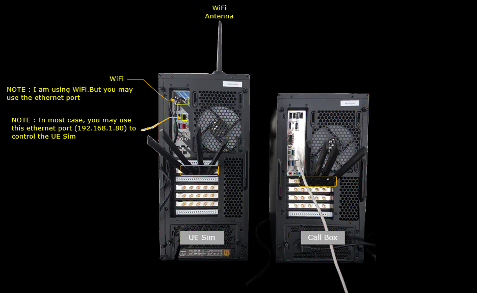
Test setup for this tutorial is as shown below.
The Callbox runs the gNB, and the UEsim plays the role of the UE. One SDR card is used on each side. The two SDR cards are connected directly with four RF cables, so no over the air radio is involved.
Key Configuration Parameters
Followings are important configuration parameters for this tutorial. You may click on the items for the descriptions from Amarisoft documents.
- pdsch
Test 1 : PDSCH Aggregation -TDD
This test is to test PDSCH Aggregation Factor operation in NR SA TDD
Configuration
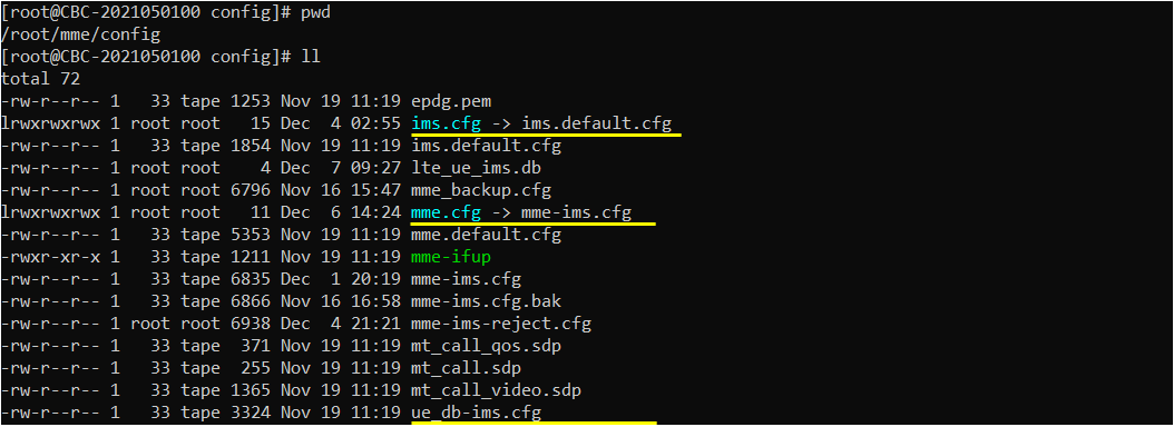
I used the gnb-sa-pdsch-agg.cfg on gNB which is copied and modified from gnb-sa.cfg

I used ims.default.cfg as ims configuration and mme-ims.cfg as mme configuration. These two are default configuration on Callbox.
In gnb-sa-pdsch-agg.cfg , the configuration is done as follows.
I added a log option phy.rep=1 for clear verification in the log. This is not mandatory, but recommended if you want to capture all of the repeated transmission.
In this test, I used TDD. You can select any specific tdd pattern with the parameter NR_TDD_CONFIG. To apply TDD configuration, you first need to configure the duplex mode (NR_TDD) to 1 (TDD). And then I set NR_TDD_CONFIG to 2 which is one of default sample configuration provided by Amarisoft sample
configuration. (
phy.rep=1 is appended to the log_options line, next to all.level=debug and all.max_size=1. It makes the gNB PHY log print each repeated PDSCH. These are the lines you check in the Log Analysis section.
In the defines, NR_TDD is 1 and FR2 is 0. The #if FR2 branch is therefore not used in this test. In the FR1 branch, NR_TDD_CONFIG is 2 and NR_BANDWIDTH is 20 MHz. N_ANTENNA_DL is 1 (SISO) and N_ANTENNA_UL is 1. USE_SRS stays at 0.
If you want to try another TDD pattern or bandwidth, change NR_TDD_CONFIG or NR_BANDWIDTH in the #else branch.

In this test, band n78, subcarrier spacing(subcarrier_spacing) 30 is used, but this is not the mandatory condition. You can specify any band and subcarrier spacing that 3GPP allows.
With NR_TDD set to 1 and FR2 set to 0, the gNB takes the #else branch inside #if NR_TDD == 1. That branch sets band 78 and dl_nr_arfcn 632628 (3489.42 MHz). It also sets subcarrier_spacing 30 kHz and ssb_pos_bitmap "10000000".
The FR2 branch (band 257) and the FDD branch (band 7) are not used in this test. If you change the band or the frequency here, change the UE configuration to the same values.

Enabling PDSCH aggregation is simple. Just add a parameter aggregation_factor in pdsch configuration.
In this file, aggregation_factor is set to 4 inside the pdsch object of nr_cell_default. The rest of the pdsch block is the same as in gnb-sa.cfg. mapping_type is "typeA" and mcs_table is "qam256". k0 and k1 are left to automatic setting, and mcs stays commented out. The PDSCH MCS is therefore computed from the DL channel quality estimation.
aggregation_factor accepts 1, 2, 4 or 8, and the default is 1. When it is greater than 1 and the UE supports it, the gNB configures pdsch-AggregationFactor for PDSCH in this BWP. With 4, each scheduled PDSCH is sent in four consecutive slots. If you want fewer or more repetitions, change this value to 2 or 8.
If repetition_scheme is also configured and the UE supports both features, aggregation_factor is ignored. So do not set repetition_scheme when you test PDSCH aggregation.

I used the ue-nr-sa.cfg as it is.
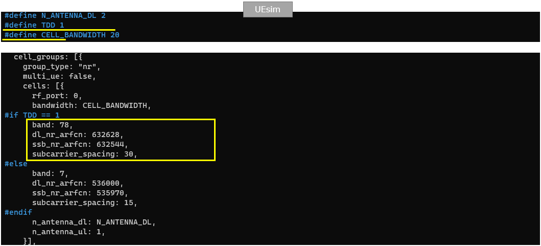
Configure UE as TDD which matches to callbox configuration. Set the band, subcarrier spacing(subcarrier_spacing), channel frequency(dl_nr_arfcn) and SSB frequency(ssb_nr_arfcn) to match with Callbox configuration.
At the top of the UE file, TDD is defined as 1 and CELL_BANDWIDTH as 20. These match NR_TDD and NR_BANDWIDTH on the gNB. N_ANTENNA_DL is 2 on the UE side, and n_antenna_ul is 1.
With TDD at 1, the UE takes the #if TDD == 1 branch. It sets band 78, dl_nr_arfcn 632628, ssb_nr_arfcn 632544 and subcarrier_spacing 30. These are the same values that the gNB reports in the 'cell phy' output. The #else branch with band 7 is not used in this test.
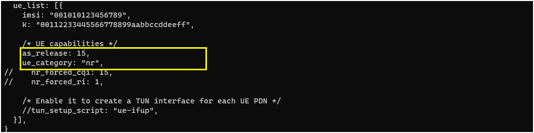
Set UE access release (as_release) to 15 and ue_category to "nr".
These two lines are in the UE capabilities part of ue_list, below the imsi "001010123456789" and the K key. nr_forced_cqi and nr_forced_ri stay commented out, so CQI and RI follow the real channel. I did not add any other UE parameter for PDSCH aggregation.
Perform the Test
Start LTE service (gNB) and run 'cell phy' and 'cell' command, then everything is configured as you intended.
'cell phy' shows one NR cell on band n78 with a bandwidth of 20 MHz. DL and UL both use ARFCN 632628, 1 antenna, 1 layer, SCS 30 and QAM 256. The SSB is at ARFCN 632544 with SCS 30.
'cell' shows the same cell with TAC 0x000064, pci 500 and PLMN 00101. If any of these values differ from what you configured, check the enb.cfg link before going further.

Power on UE on UE sim using power_on command.
Before power_on, I set the UE log with 'log file.rotate=250M,file.path=/var/log/lte/'. This step is optional. It only decides where the UE log is written.

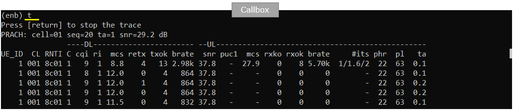
Confirm that the UE completes the attach and check the throughput with 't' command.
The 't' command is run on the gNB console. After the PRACH line, UE_ID 1 with RNTI 8c01 appears on cell 001. The DL cqi is 8 to 9 and ri is 1. The DL mcs stays around 12.0, and the snr is 37.8.
From the second line on, txok is 4 and the DL brate is about 864. This trace only confirms that the UE is attached and being scheduled. The repetitions themselves are checked in the PHY log.
Log Analysis
Before you start logging (i.e, before you turn on UE) I would suggest to check 'Repetition' in eNB log property window for more detailed verification.
To open this window, select ENB in the server list and click the settings button at the top left. Under Phy flags, check Repetitions and click Update. The other phy flags can stay unchecked.
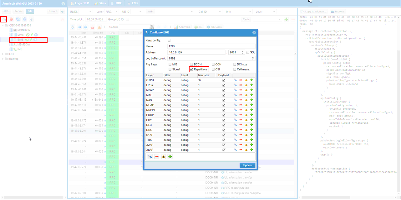
Once the initial attach is done, check UE capability information message and see if UE support PDSCH aggregation (pdsch-RepetitionMultiSlots).
Select the UE capability information message on DCCH-NR. It comes right after the UE capability enquiry. In the decoded message, pdsch-RepetitionMultiSlots is listed as supported under phy-Parameters and phy-ParametersCommon. pusch-RepetitionMultiSlots is supported as well, on the line just above it. That one is for PUSCH aggregation and is not used in this test.

If UE notifies that pdsch-RepetitionMultiSlots is supported, gNB enables the PDSCH Aggregation by setting pdsch-AggregationFactor in pdsch-Config IE (Information Element)
The gNB sends this in the RRC reconfiguration on DCCH-NR, after the UE capability information. pdsch-AggregationFactor n4 is in pdsch-Config setup under initialDownlinkBWP. n4 comes from aggregation_factor 4 in the gNB configuration. The full message is listed in the RRC / NAS Signaling section.

Once PDSCH aggregation is enabled, you can check in PHY log to confirm that it is really working as expected.
First find any PDCCH/DCI 1_1 that schedule a PDSCH and then check a few consecutive PDSCH. You see the first PDSCH log after the PDCCH is printed with n_rep and the following three PDSCH are transmitted with different rep values and rv_idx values without any separate PDCCH/DCI 1_1. The k1 value in this case is calculated from the last repetition of PDSCH.
In this run, the DCI is ss_id=2 cce_index=2 al=2 dci=1_1, sent at 19:47:12.161. The first PDSCH in slot 14.775.1 has harq=0, prb=50, symb=1:13, k1=5 and n_rep=4. Its rv_idx is 0, mod is 6 and tb_len is 72.
The next three PDSCH come in slots 14.775.2, 14.775.3 and 14.775.4 with the same harq=0 and prb=50. They carry rep=1, rep=2 and rep=3, and rv_idx 2, 3 and 1. So the redundancy version moves through 0, 2, 3, 1 over the four slots.
The ACK comes on PUCCH format=1 in slot 14.775.9 with ack=1. That is k1=5 slots after the last repetition in slot 14.775.4, not after the first one. The decoded DCI fields show mcs1=15, harq_process=0 and harq_feedback_timing=3. A few lines lower, the next DCI 1_1 starts another group with k1=12 and n_rep=4.

You can confirm the transmission of the aggregated PDSCH in visual way on the WebGUI. As shown here, you see the 4 consecutive PDSCH. First transmission is marked in dark color and the following repetition is marked in ligher colors.
To open this view, click the RB button in the log toolbar. The four PDSCH blocks are at the top of the grid, around 19:47:12.155. The green block after them is the PUCCH carrying the ACK. The gap between the last repetition and the PUCCH is k1, the same k1 seen in the PHY log.

RRC / NAS Signaling
This section lists the RRC message that turns PDSCH aggregation on for the UE. It is the full text of the RRC reconfiguration checked in the Log Analysis section, so you can compare it with your own log.
RrcReconfiguration (SA)
: This is the RrcReconfiguration sent by gNB to configure PDSCH Aggregation Factor. (
{
message c1: rrcReconfiguration: {
rrc-TransactionIdentifier 0,
criticalExtensions rrcReconfiguration: {
nonCriticalExtension {
masterCellGroup {
cellGroupId 0,
spCellConfig {
spCellConfigDedicated {
initialDownlinkBWP {
pdsch-Config setup: {
resourceAllocation resourceAllocationType1,
pdsch-AggregationFactor n4,
rbg-Size config1,
mcs-Table qam256,
prb-BundlingType staticBundling: {
bundleSize wideband
}
}
},
uplinkConfig {
initialUplinkBWP {
pusch-Config setup: {
txConfig codebook,
resourceAllocation resourceAllocationType1,
mcs-Table qam256,
mcs-TableTransformPrecoder qam256,
codebookSubset nonCoherent,
maxRank 1
}
}
},
pdsch-ServingCellConfig setup: {
nrofHARQ-ProcessesForPDSCH n16,
maxMIMO-Layers 1
},
tag-Id 0
}
}
},
dedicatedNAS-MessageList {
'7E020F53BDA1017E0042010977000BF200F110800101CAA35AD154070000F11000006415020101210203005E01BE3408031F19F1031F11F2'H
}
}
}
}
}