NR SA - Network Slicing
The purpose of this tutorial is to show you how to test Network Slices. The purpose of this tutorial is to show how to configure different slices in terms of signaling message, not to show different traffic flows via each of the slide. In terms of the signaling messages, Network slicing configuration is configured by following messages.
- Registration Request : UE informs network on which slice it wants to use. UE can specify one or more of slices at this step.
- Requested NSSAI
- Network Slicing Indication
- Registration Accept : Network informs UE on what kind of slices are allowed and which slice is configured for the UE.
- Allowed NSSAI
- Configured NSSAI
- Network Slicing Indication
- NSSAI Inclusion Mode
Table of Contents
- NR SA - Network Slicing
- Introduction
- Summary of the Tutorial
- Test Setup
- Key Configuration Parameters
- Test 1 : Network Slice with default settings - Commericial UE
- Test 2 : Network Slice with Single Slices - UEsim
- Test 3 : Network Slice with Multiple Slices - UEsim
- Test 4 : Network Slice with RAN Slices - UEsim
- Test 5 : URSP - UEsim
- RRC / NAS Signaling
Introduction
Network slicing is a foundational capability introduced in 5G networks, enabling the creation of multiple virtualized and independent logical networks over a shared physical infrastructure. This technology allows operators to dynamically allocate resources and tailor network characteristics—such as latency, throughput, and security—to meet the diverse requirements of varied services, industries, and customer segments. Architecturally, network slicing is achieved by partitioning network functions and resources across the Radio Access Network (RAN), transport, and core network layers. Each network slice operates as a self-contained, end-to-end instance, defined by a specific set of network policies and configurations, and is identified using the Network Slice Selection Assistance Information (NSSAI), which includes the Slice/Service Type (SST) and Slice Differentiator (SD). The management and orchestration of these slices are governed by 5G core network functions and standard procedures, such as slice selection during device registration and session setup. The significance of network slicing lies in its flexibility and scalability, empowering service providers to offer customized connectivity solutions for applications ranging from enhanced mobile broadband to mission-critical communications and massive IoT deployments. Within the broader 5G ecosystem, network slicing is pivotal for realizing the promise of highly adaptable, service-oriented networks and is a key enabler for vertical industries seeking differentiated network services.
-
Context of Network Slicing
- 5G Network Evolution: Network slicing is a core architectural feature in 5G, designed to address the needs of diverse applications and business models by enabling logical segmentation of network resources.
- Key Concepts: Includes slice selection, NSSAI, dynamic resource allocation, and end-to-end isolation of services.
- Architectural Overview: Slices span RAN, core, and transport domains, and are orchestrated via management frameworks that ensure consistent performance and security.
-
Relevance and Importance of This Tutorial
- Practical Configuration: Understanding how to configure and validate network slices at the signaling level is essential for engineers, testers, and network administrators implementing 5G solutions.
- Standard Procedures: The tutorial focuses on the signaling procedures—such as Registration Request and Registration Accept messages—used to negotiate and establish slice configurations between the User Equipment (UE) and the network.
- Industry Adoption: Mastery of network slicing concepts is critical for leveraging the full capabilities of 5G infrastructure, supporting new services and business models.
-
What Learners Will Gain
- Hands-on Understanding: Step-by-step guidance on how to test network slice configuration using signaling messages.
- Technical Insights: Knowledge of how the NSSAI and related parameters are exchanged and interpreted during registration.
- Tool Proficiency: Familiarity with platforms like Amarisoft, and understanding the extent of their slicing support (e.g., bearer and core network-level slicing).
-
Prerequisite Knowledge and Skills
- 5G Architecture: Basic understanding of 5G network components and signaling flow.
- Core Network Concepts: Familiarity with 5G core functions (AMF, SMF, etc.) and protocol layers.
- Protocol Analysis: Experience with analyzing signaling messages (e.g., Registration Request/Accept) using suitable tools.
Summary of the Tutorial
This tutorial demonstrates several test procedures for verifying network slicing functionality using both commercial UEs and Amarisoft UEsim. The steps cover configuration, execution, and analysis of network slice behaviors under different scenarios, including default, single, multiple, and RAN slice cases, as well as USRP/UE policy management testing.
-
Test Setup
- Setup 1: Used when a commercial UE is the Device Under Test (DUT).
- Setup 2: Used when Amarisoft UEsim is the DUT.
-
Key Configuration Parameters
- Configuration involves parameters for eNB, MME, and UEsim related to PLMN, NSSAI, slices, and PDN associations. Matching configurations between network and UE is essential for correct network slice operation.
-
Test 1: Network Slice with Default Settings - Commercial UE
-
Procedure:
- Ensure proper configuration files are used for gNB, MME, and UE DB (typically default files with no slice-specific modifications).
- Confirm network slice configuration in the callbox matches the expected default NSSAI (usually SST:1 for eMBB).
- Power on the UE and verify attachment to the network, with successful IP address allocation.
-
Log Analysis:
- Registration Request and Accept messages are checked to confirm the requested and allowed NSSAI.
- Observe the PDU Session Establishment flow to verify the assigned S-NSSAI.
-
Procedure:
-
Test 2: Network Slice with Single Slice - UEsim
-
Procedure:
- Use modified configuration files for gNB, MME, UE DB, and UEsim to define a single network slice ({sst:1, sd:1}).
- Ensure all configurations are aligned: only one slice is set in both Requested and Allowed NSSAI.
- Power on the UEsim, verify attachment, and confirm IP allocation.
-
Log Analysis:
- Inspect Registration Request and Accept messages to check that a single slice is negotiated.
- Analyze the PDU session establishment to confirm proper S-NSSAI use.
-
Procedure:
-
Test 3: Network Slice with Multiple Slices - UEsim
-
Procedure:
- Configure multiple slices in gNB, MME, UE DB, and UEsim (e.g., {sst:1, sd:1}, {sst:2}, {sst:3, sd:50}).
- Set two or more network slices in Requested NSSAI and ensure network allows multiple slices in Allowed NSSAI.
- Power on the UEsim, verify network attachment, and confirm correct IP address assignment.
-
Log Analysis:
- Validate that multiple slices are present in Registration Request and Accept messages.
- Observe PDU session establishment for each requested slice.
-
Procedure:
-
Test 4: Network Slice with RAN Slices - UEsim
-
Procedure:
- Use default UE configuration and specific gNB/MME configs with RAN slicing enabled.
- Attach UEsim to the network, then use a remoteAPI command to trigger a PDU session with a specified slice ({sst:3, sd:50}) on a particular APN ("internet").
- Confirm, via core network and PHY traces, that two PDUs are active: one default and one user-triggered with explicit slicing.
-
Log Analysis:
- Monitor initial registration and subsequent PDU session establishment for allocation of correct slices.
- Check that the triggered PDU session uses the user-specified NSSAI and DNN.
-
Procedure:
-
Test 5: USRP (Manage UE Policy Command) - UEsim
-
Procedure:
- Use the same configuration as Test 2.
- Power on UE, ensure attachment and IP assignment.
- Use the remoteAPI to send a "Manage UE Policy Command" (URSP) to the MME. The command structure includes IMSI, IMEI, PLMN, policy sections, and URSP rules with traffic descriptors and route selection descriptors.
- Verify command execution through output logs and the presence of the correct NAS message.
-
Log Analysis:
- Confirm that DL NAS transport carries the Manage UE policy command with the policy data as specified in the remoteAPI command.
-
Procedure:
General Execution Steps for All Tests:
- Ensure testbed configuration matches the intended test scenario (commercial UE or UEsim).
- Align network and UE configuration files before powering on the DUT.
- After powering on, verify network attachment and IP address assignment.
- For advanced scenarios (e.g., RAN slices, USRP), use remoteAPI tools to trigger specific behaviors or policy updates.
- Perform log analysis to verify that the correct slices, policies, and session behaviors are established as per the configuration and test objectives.
Summary: The tutorial provides step-by-step methodologies for validating network slice configuration, association, and management across different use cases, emphasizing the importance of configuration alignment, execution sequence, and log verification without exposing full protocol message structures.
Test Setup
I used two different setups for the test in this tutorial depending on the type of DUTs for each test. When I used a commercial UE as DUT, I used <Setup 1> and when I used a Amarisoft UEsim as DUT I used <Setup 2>.
< Setup 1 >

< Setup 2 >
Test setup with UEsim for this tutorial is as shown below.

Key Configuration Parameters
Followings are important configuration parameters for this tutorial. You may click on the items for the descriptions from Amarisoft documents.
- enb config
- nssai : In this link, you will get the descriptions for all the items listed below
- sst
- sd
- mme config
- Uesim Config
Test 1 : Network Slice with default settings - Commericial UE
This is to show a very basic test with Commercial UE. It is with almost basic configuration. In most case, commercial UE does not provide any way for the user to change Network Slice configuration on UEside. So it would be good to figure out the network slice configuration on UE before the test.
Configuration
An important thing in using UE sim is to do proper matching between UE sim configuration and Call box configuration In thisTest, I used the gnb-sa .cfg without any change.
If you use other Network (e.g, other network simulator or real network), you have to make it sure to configure UE sim according to the settings on network side

In this test, I used the default configuration for core network(i.e, mme-ims.cfg, ims.default.cfg and ue_db-ims.cfg).

Following is the configuration for network slice in gnb-sa .cfg
nssai in plmn_list defines the list of slices supported by this PLMN and tracking area.
In this example, the cell belongs to PLMN 00101 and TAC 100. Under this PLMN entry, nssai lists the S-NSSAIs that this tracking area can support. The enabled slice is sst: 1, which usually represents eMBB.
The other slice examples, such as sst: 2 and sst: 3 with sd: 50, are commented out. So they are not active in the default configuration. If you want to test additional slices, those entries should be uncommented or added according to the target test scenario.
This nssai setting works together with the nssai configuration in mme.cfg. The network uses these two configurations to decide which slices can be allowed for the UE. As a result, the allowed NSSAI is included in the Attach Accept message.
If nssai is not configured here, Amarisoft assumes the default NSSAI, which is sst: 1. This means the UE will be treated as using the default eMBB slice unless additional slice information is explicitly configured.

Following is the configuration for slice in mme-ims.cfg. nssai in mme.cfg indicates the list of nssai supported by the mme.
In this example, the nssai block is commented out. So these slice entries are not enabled in the default configuration. The listed examples include sst: 1, sst: 2, and sst: 3 with sd: 50, but they do not take effect unless the comment markers are removed.
This configuration works together with the nssai setting in enb.cfg. The enb.cfg side defines which slices are supported by the PLMN and tracking area. The mme.cfg side defines which slices are supported by the MME or AMF side. Amarisoft compares these settings and uses them to determine the allowed NSSAI for the UE.
The result is sent to the UE in the Attach Accept message.
If this nssai configuration is not enabled, Amarisoft assumes the default slice, which is sst: 1. This is usually treated as the default eMBB slice.

In this test, the slice configuration is applied to the internet PDN.
The access_point_name is set to internet, so this PDN profile is used when the UE requests the internet APN during attach or PDN connectivity procedure.
The PDN type is ipv4, and the UE will receive an IPv4 address from the range between 192.168.3.2 and 192.168.3.254. The dns_addr field provides the DNS server address that will be given to the UE.
The erabs section defines the bearer configuration for this PDN. In this example, QCI 9 is used, which is normally used for default non-GBR data service. This is suitable for a normal internet data bearer.
For the network slicing test, this means that the slice selection will be associated with the internet APN. When the UE establishes the internet PDN, the network can apply the configured S-NSSAI to this PDN connection. So the test is not using a separate APN for slicing. Instead, it applies slice information to the regular internet PDN.

slices[] is not used in this test because this block is commented out.
If this block is enabled, you can map a specific S-NSSAI to a specific QoS flow. This allows the PDN or PDU session to use different slice-specific QoS settings depending on the selected slice.
In this example, one slice uses sst: 1 and maps it to a QoS flow with 5QI 6. Another slice uses sst: 3 and sd: 50 and maps it to a QoS flow with 5QI 7. Each QoS flow also has its own priority level, pre-emption capability, and pre-emption vulnerability.
This kind of configuration is useful when you want to test slice-dependent QoS behavior. For example, one slice may be configured for normal broadband traffic, while another slice may be configured for a different service type with different QoS characteristics.
For this test, however, this part is not enabled. So the test focuses on basic NSSAI handling and applying the slice to the internet PDN, not on per-slice QoS flow differentiation.

Following is the configuration for network slice in ue_db-ims.cfg.
In this test, the UE database includes the normal subscriber information such as IMSI, authentication key, IMPI, IMPU, domain, and multi_sim setting. These parameters are enough for the UE to attach, perform authentication, and use IMS-related services.
No pdn_list is configured in this UE profile. This means the UE does not have a UE-specific PDN or slice restriction defined here.
So, for this network slicing test, the slice decision is mainly controlled by the network-side configuration, such as nssai in enb.cfg and nssai in mme.cfg, rather than by a specific PDN list inside the UE database.
As a result, when the UE attaches and requests the internet PDN, Amarisoft uses the default or network-configured NSSAI information to determine the allowed NSSAI and apply the slice behavior.

Perform the Test
Start the test by checking the basic NR cell configuration.
The cell phy command shows that the gNB is running with PLMN 00101 and gNB ID 0x12345. The cell is configured as NR Band n78 with 20 MHz bandwidth.
The downlink ARFCN is 632628 and the uplink ARFCN is also 632628, which indicates TDD operation. The subcarrier spacing is 30 kHz for both downlink and uplink. The SSB ARFCN is 632544, also using 30 kHz SCS.
This step is mainly to confirm that the NR cell is configured and running as expected before checking the slicing behavior. Network slicing itself is not verified from this command, but this confirms that the radio cell is active and ready for UE registration and PDU session testing.

Power on the UE and make sure that it attaches to the NR cell.
The enb t command shows the live radio trace for the connected UE. In this example, UE_ID 1 is active on cell 001 and has C-RNTI 4601. This means the UE has established radio connection with the gNB.
The DL and UL columns show that data is being exchanged between the UE and the network. You can see changing MCS, bitrate, retransmission, and SNR values. This indicates that the UE is not only detected, but actively communicating with the cell.
This step confirms the basic UE attachment and radio link operation. Before checking Network Slicing behavior, the UE should first be attached successfully and should have a stable connection with the NR cell.

Confirm that the UE has completed registration and received an IP address.
The mme ue command shows the UE status from the core network side. In this example, REG is Y, so the UE is registered to the 5GC. The CN type is shown as 5GC, which means the UE is connected through the 5G core path.
The TAC value is 0x64, which matches the configured tracking area. The number of bearers is 1, meaning one user-plane connection is established for the UE.
The IP_ADDR field shows 192.168.3.2. This is the IP address assigned to the UE for the internet PDN or PDU session.
This is an important checkpoint before checking Network Slicing. If the UE is not registered or does not receive an IP address, the slicing result cannot be properly verified yet. In that case, troubleshoot the registration and PDU session establishment first.

Log Analysis
In this section, I will show you only the portions of the log that are relavent to this tutorial. For the full log, refer to the sample log linked aboved.
In the Registration Request message, the UE includes the requested NSSAI.
In this example, the UE requests S-NSSAI with SST 1. This means the UE is asking the network to allow the default slice, usually used as the eMBB slice.
This requested NSSAI comes from the UE-side configuration. It is not decided by the gNB or core network at this point. The UE sends its preferred or configured slice information during the registration procedure.
The right-side decoded NAS panel shows Requested NSSAI and S-NSSAI contents = 1, with SST = 0x01. This confirms that the UE requested SST 1 in the Registration Request.
If you want the UE to request another slice, such as SST 2 or SST 3 with SD, you need to change the UE configuration. Then the Registration Request should show the updated requested NSSAI value.

In the Registration Accept message, the core network includes the Allowed NSSAI.
In this example, the Allowed NSSAI contains S-NSSAI with SST 1. This means the Amarisoft core network accepted the slice requested by the UE and allowed the UE to use SST 1.
The right-side decoded NAS panel shows Allowed NSSAI, S-NSSAI contents = 1, and SST = 0x01. This confirms that the network selected and returned the same slice that the UE requested in the Registration Request.
This is the key point of the slicing test. The UE first requests NSSAI during Registration Request, and the core network checks it against the configured NSSAI in the gNB and MME/AMF configuration. If the requested slice is supported and allowed, the core network sends it back in the Allowed NSSAI IE of the Registration Accept message.
So this message confirms that slice negotiation during registration was successful for SST 1.

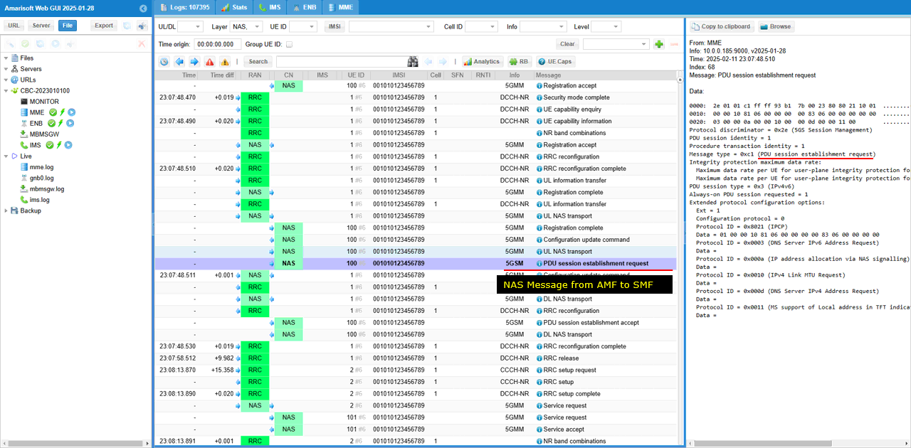
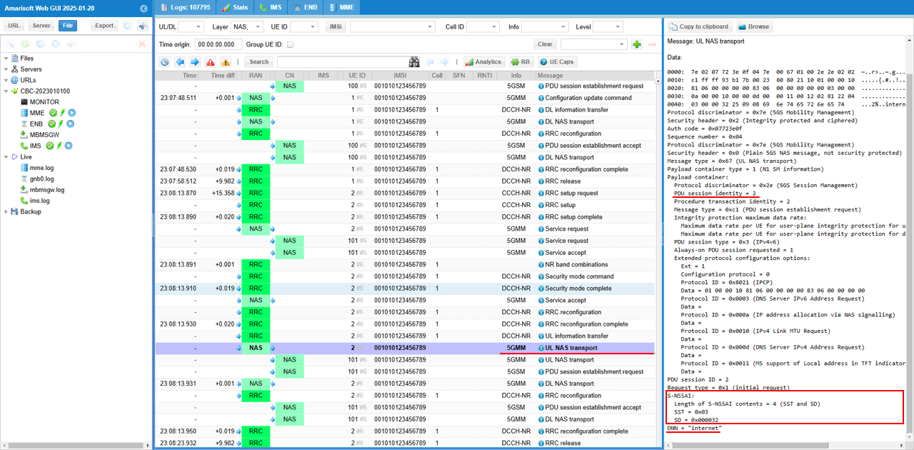
You can confirm the DNN used for the PDU session in the PDU Session Establishment Request.
In this example, the UE sends a PDU Session Establishment Request after registration is completed. This message is carried inside UL NAS Transport.
In the decoded message on the right side, the DNN is shown as internet. This means the UE is requesting a PDU session for the internet data network.
This is important for this slicing test because the slice is being applied to the internet PDN or DNN. So the test is not only checking that the UE received Allowed NSSAI during Registration Accept. It also checks that the actual user-plane session is established for the intended DNN.
If the DNN shown here is different from the expected one, the slice may be applied to a different service profile or the PDU session may not match the configuration you intended to test.

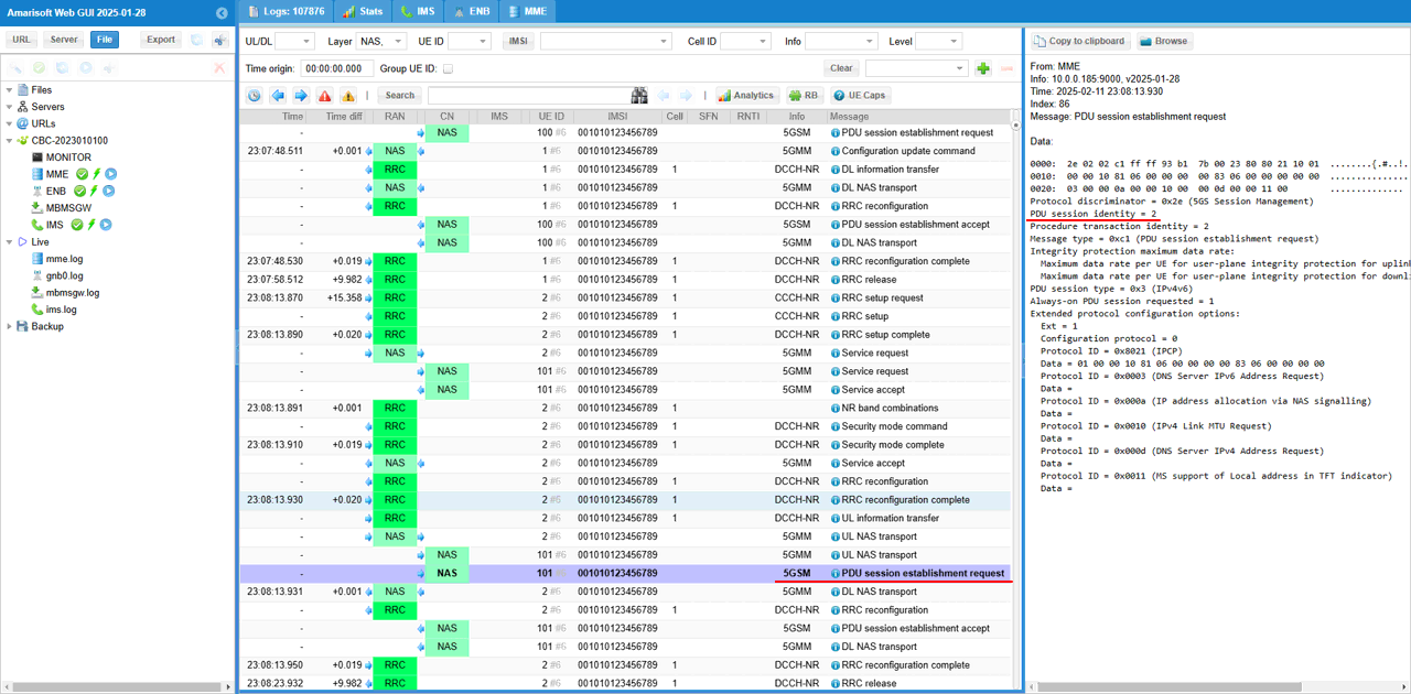
Now the UE starts the user-plane session setup by sending PDU Session Establishment Request.
This message is sent after the UE completes 5G registration. In the log, it is carried inside UL NAS Transport and delivered from the UE to the core network.
The message type is PDU session establishment request. This means the UE is asking the 5GC to create a PDU session for data service. In this test, the requested service is the internet DNN.
This step is important in the slicing test because the registration procedure only tells which slice is allowed for the UE. The actual data connection is created later through the PDU session establishment procedure. During this procedure, the network can associate the requested DNN with the allowed S-NSSAI and create the proper user-plane path.
So this message indicates that the UE has moved from slice registration into actual PDU session setup for data service.

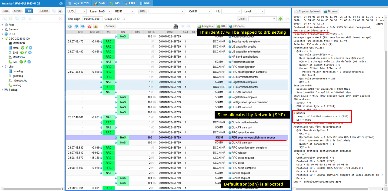
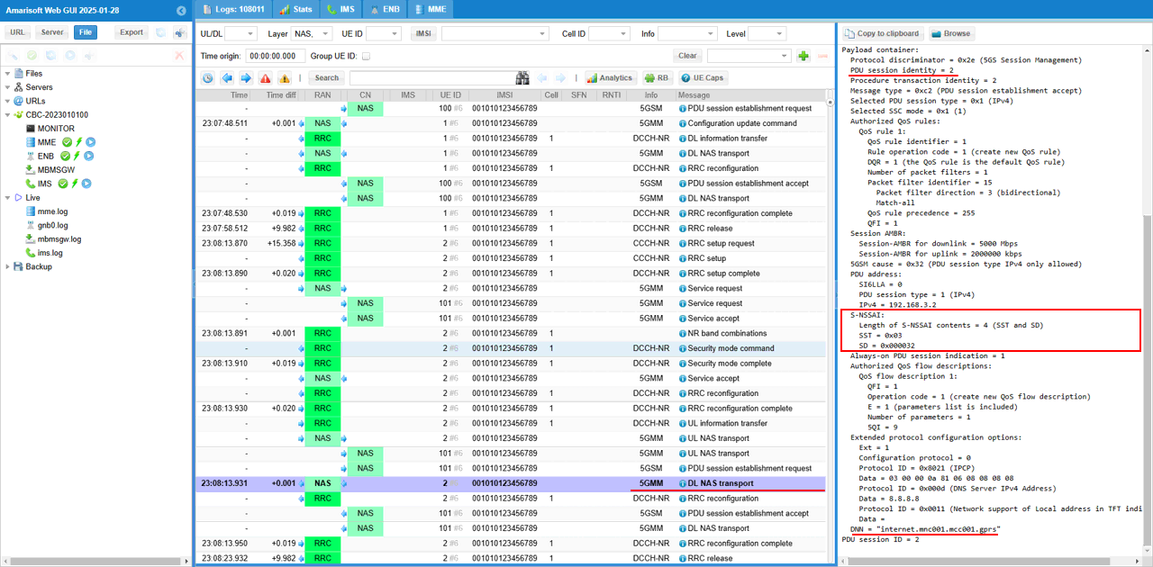
The network completes the PDU session setup by sending PDU Session Establishment Accept.
This message tells the UE that the requested PDU session has been accepted and created by the core network. In this example, the selected PDU session type is IPv4, and the UE is assigned the IPv4 address 192.168.3.2.
The important part for the slicing test is the S-NSSAI IE inside this message. It shows S-NSSAI contents = 1 and SST = 0x01. This means the PDU session is associated with slice SST 1.
So the slicing information is confirmed in two places. First, the Registration Accept tells the UE which NSSAI is allowed. Then, the PDU Session Establishment Accept tells the UE which S-NSSAI is actually used for this specific PDU session.
This confirms that the internet PDU session has been established using the allowed network slice.

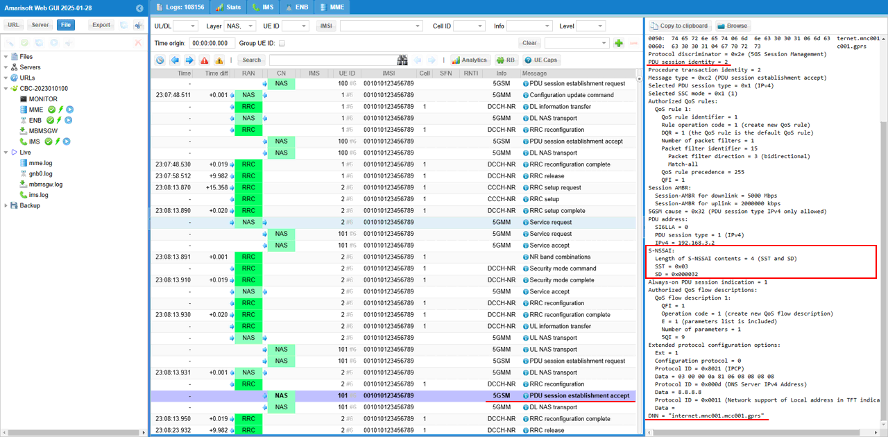
The PDU Session Establishment Accept is delivered to the UE inside a DL NAS Transport message.
In the log, the outer NAS message is DL NAS Transport. This means the core network is sending a NAS payload downlink to the UE. Inside this transport message, the actual 5G Session Management message is included.
The decoded panel shows that the carried message is PDU Session Establishment Accept. This confirms that the network has accepted the UE�s PDU session request.
The S-NSSAI IE is included in this accepted PDU session information. In this example, the S-NSSAI contains SST 0x01. This tells the UE that this PDU session is associated with slice SST 1.
So this log shows both the NAS delivery method and the slice association. DL NAS Transport carries the PDU Session Establishment Accept, and the accept message includes the S-NSSAI used for the established PDU session.

Test 2 : Network Slice with Single Slices - UEsim
This is to show on how to configure single Network Slice and test with Amarisoft UEsim. Since we have full control over UE configuration with Amarisoft UEsim, we can test DUT with more detailed configurations.
Configuration
An important thing in using UE sim is to do proper matching between UE sim configuration and Call box configuration In this tutorial, I used the ue-nr-sa-slice-single.cfg that is copied and modified from the ue-nr.cfg and gnb-sa-slice.cfg that is copied and modified from gnb-sa.cfg. The mme configurations that are used for this test are mme-ims-slice-single.cfg and ue_db-ims-slice-single.cfg which are copied and modified from mme-ims.cfg and ue_db-ims.cfg
If you use other Network (e.g, other network simulator or real network), you have to make it sure to configure UE sim according to the settings on network side
I used gnb-sa-slice.cfg for enb configuration. gnb-sa-slice.cfg is copied and modified from gnb-sa.cfg

For core network configuration, I used mme-ims-slice-single.cfg which is copied and modified from mme-ims.cfg. For UE database, I used ue_db-ims-slice-single.cfg which is copied and modified from ue_db-ims.cfg

For the UEsim, I used ue-nr-sa-slice-single.cfg which is copied and modified from ue-nr-sa.cfg

Following is the configuration in gnb-sa-slice.cfg .
In this configuration, three network slices ({sst:1, sd:1}, {sst:2}, {sst:3, sd:50}) are configured for the gNB (
The configured slices are sst 1 with sd 1, sst 2 without sd, and sst 3 with sd 50. This means the gNB advertises or supports these slices for PLMN 00101 and TAC 100.
sd is optional. A slice can be identified only by sst, or by the combination of sst and sd. In this example, sst 2 is configured without sd, while sst 1 and sst 3 include sd values.
However, configuring three slices here does not mean that all three slices will be used by the UE. This setting only defines what the network side can support in this tracking area.
In this test, only one slice will actually be requested by UEsim and allowed by the network. So this configuration provides multiple supported slice candidates, but the actual slice used in the test is decided by the UE Requested NSSAI and the network Allowed NSSAI.

Followings are the configurations in mme-ims-slice-single.cfg
Same as in gNB configuration, three network slices ({sst:1, sd:1}, {sst:2}, {sst:3, sd:50}) are configured for the CORE Network.
The nssai block defines which network slices are supported by the AMF or core network. In this example, the core network supports sst 1 with sd 1, sst 2 without sd, and sst 3 with sd 50.
This should match the slice configuration on the gNB side. The gNB configuration tells which slices are supported in the cell or tracking area, and the MME/AMF configuration tells which slices are supported by the core network.
Even though three slices are configured here, this does not mean that all three slices are used in the test. These are only the slice candidates that the network can allow.
For this single-slice test, UEsim will request only one slice. Then the core network checks whether that requested slice is included in this nssai list. If it is supported, the network returns it as the Allowed NSSAI in the Registration Accept message.

Two of the network slices are associated with "internet" PDU for different 5QI. Slice {sst:1, sd1} is associated with 5QI 6 and {sst:3,sd:50} is associated with 5QI 7.
In this configuration, the internet PDN is used as the data service, but different network slices can be associated with different QoS flows.
The main PDN configuration still defines the internet APN, IPv4 address pool, DNS, and the default bearer setting. The default bearer uses QCI 9, which is a normal non-GBR data bearer.
The slices block adds slice-specific QoS behavior under the same internet PDN.
For the slice with sst 1 and sd 1, the configured QoS flow uses 5QI 6 with priority level 9.
For the slice with sst 3 and sd 50, the configured QoS flow uses 5QI 7 with priority level 8.
This means the same internet PDU session configuration can behave differently depending on which S-NSSAI is selected. If the UE requests and is allowed to use sst 1 with sd 1, the network applies the QoS flow configured for that slice. If the UE uses sst 3 with sd 50, the network applies the other QoS flow.
So this part of the configuration connects three concepts together: DNN, S-NSSAI, and QoS flow. The DNN is internet, the selected S-NSSAI identifies the slice, and the QoS flow defines the service behavior for that slice.


include ue_db-ims-slice-single.cfg tells the core network to load the UE subscriber configuration from a separate file prepared for this single-slice test.
This file contains the UE identity, authentication information, IMS-related identities, and UE-side slice-related settings used by Amarisoft UEsim.
For this test, this is important because the requested NSSAI is controlled from the UE configuration. By including ue_db-ims-slice-single.cfg, the core network uses the UE profile that is matched with the intended single-slice scenario.
So mme-ims-slice-single.cfg defines the network-side slice support, while ue_db-ims-slice-single.cfg defines the UE subscription and UE-side slice request behavior. Together, they determine what slice the UE requests and what slice the network allows.
![]()
Followings are the configurations in ue_db-ims-slice-single.cfg
You can manually specify the APN name and the associated Network slice in pdn_list configuration parameter in UE DB on Callbox. In this test case, the "internet" APN is set as default PDU and {sst:1, sd:1} is the network slice mapped to this PDU.
In this example, access_point_name is set to internet, and default is set to true. This means the internet PDU session is treated as the default PDU session for this UE.
The important slicing part is nssai. Here, the internet PDU session is mapped to sst 1 with sd 1. So when this UE establishes the internet PDU session, it is expected to use this specific S-NSSAI.
This makes the UE subscription more explicit than the previous test. Instead of relying only on the general network-side NSSAI configuration, the UE database directly says that the internet APN is associated with the slice sst 1, sd 1.
So in this single-slice test, UEsim should request only this slice for the internet PDU session, and the network should allow the same slice if it is supported by both the gNB and the core network configuration.

Followings are the configurations in ue-nr-sa-slice-single.cfg (
On UEsim configuration as well, you can specify the default apn and the default network slice that is mapped to the apn. Here in this test, "internet" is set as the default APN and {sst:1, sd:1} is configured as the default network slice.
The apn is set to internet, so UEsim will try to establish the default data connection using the internet DNN. attach_pdn_type is set to ipv4, so the requested PDU session type is IPv4.
default_pdu_session_snssai defines the S-NSSAI that UEsim sends during the PDU Session Establishment Request. In this example, it is configured as sst 1 and sd 1. This means the UE requests the internet PDU session using this specific slice.
default_nssai defines the default configured NSSAI of the UE. In this example, it also contains sst 1 and sd 1. This is the slice information that the UE uses as its configured slice preference during registration.
So, in this single-slice UEsim test, both the default APN and the default slice are explicitly controlled by the UE configuration. The UE requests only the internet APN and only the slice sst 1, sd 1. Then the network checks this against the gNB and core network slice configuration and returns the allowed slice if it is supported.

Perform the Test
Check with cell parameter and see if it is configured as intended. The cell phy command shows that the gNB is running with PLMN 00101 and gNB ID 0x12345. The cell is configured as NR Band n78 with 20 MHz bandwidth.
The downlink and uplink ARFCN are both 632628, so this is a TDD cell. The subcarrier spacing is 30 kHz for both downlink and uplink. The SSB is configured at ARFCN 632544 with 30 kHz SCS.
This step does not directly verify the slice configuration yet. It is a basic sanity check before starting UEsim. The cell should be active and configured as expected first, so that UEsim can camp on the NR cell, register to the 5GC, and then request the configured single slice.
Power on UEsim and make sure that it attaches to the NR cell.
The enb t command shows the live radio trace from the gNB side. In this example, UE_ID 1 is connected to cell 001 and has C-RNTI 4601. This means the UE has established the radio connection with the gNB.
The DL and UL sections show active scheduling and traffic information. You can see MCS, bitrate, retransmission count, SNR, and other radio link values changing over time. This indicates that the UE is not only detected, but actively communicating with the cell.
This is the first runtime checkpoint for the single-slice UEsim test. Before checking Requested NSSAI, Allowed NSSAI, or PDU session S-NSSAI, the UE should first be attached and stable on the NR cell.
Confirm that UEsim has completed registration and received an IP address.
The mme ue command shows the UE status from the core network side. In this example, REG is Y, so the UE is registered to the 5GC.
The CN type is 5GC, which means the UE is connected through the 5G core. The TAC is 0x64, matching the configured tracking area. The number of bearers is 1, which means one PDU session or user-plane connection has been established.
The IP_ADDR field shows 192.168.3.2. This is the IPv4 address assigned to the UE for the internet PDU session.
This confirms that the basic registration and PDU session setup are successful. If the UE does not appear here, or if the IP address is missing, you should troubleshoot registration, authentication, DNN/APN configuration, or PDU session establishment before checking the network slicing result.
Log Analysis
In this section, I will show you only the portions of the log that are relavent to this tutorial. For the full log, refer to the sample log linked above.
In the UEsim case, the first Registration Request may appear as a plain 5GS NAS message with only limited information.
This can happen just after the LTE or NR service is restarted and UEsim is powered on for the first time. At this point, UEsim does not have a stored 5G security context yet. So it sends the initial Registration Request before NAS security is established.
Because the message is not security protected, it may not include all the detailed information that you expect to check, such as slice-related information.
After authentication and security mode control are completed, the UE can send another Registration Request or continue the registration procedure with protected NAS signaling. That later protected NAS signaling is where you should check the detailed information, such as Requested NSSAI, if it is not visible in the first plain NAS message.

In this case, UEsim sends the Registration Request again after NAS security setup.
The message is embedded inside Security Mode Complete. This means the UE first completes the security procedure, and then sends the Registration Request with more detailed information.
In this Registration Request, the UE includes Requested NSSAI. This value comes from the UEsim configuration file.
In this test, the requested slice is sst 1 with sd 1. The decoded message shows S-NSSAI contents including both SST and SD. SST is 0x01, and SD is 0x000001.
This confirms that UEsim is requesting the intended single slice. So this is the right place to verify whether the UE-side slice configuration is correctly reflected in NAS signaling.

Then the network sends Registration Accept with Allowed NSSAI.
In this test, the Allowed NSSAI is set to sst 1 with sd 1. This means the Amarisoft core network accepted the same slice that UEsim requested.
The decoded NAS message shows Allowed NSSAI with S-NSSAI contents including both SST and SD. SST is 0x01 and SD is 0x000001.
This confirms that slice negotiation during registration is successful. UEsim requested one configured slice in the Registration Request, and the network returned that slice as the allowed slice in the Registration Accept.
So at this point, the UE is registered with the single allowed network slice, sst 1 and sd 1.

Then UEsim starts the PDU session setup by sending PDU Session Establishment Request.
This message is carried inside UL NAS Transport. It means the UE is sending a 5G Session Management message to the core network.
In this test, the PDU Session Establishment Request includes S-NSSAI with sst 1 and sd 1. This is one of the slices already allowed by the network in the Registration Accept message.
The decoded message also shows DNN = internet. This means UEsim is requesting an internet PDU session and asking to associate that session with the slice sst 1, sd 1.
This is an important checkpoint. Registration Accept confirms which slice the UE is allowed to use, but PDU Session Establishment Request confirms which slice the UE actually uses for the data session. Here, UEsim uses the configured single slice for the internet PDU session.

Then the network completes the PDU session setup by sending PDU Session Establishment Accept.
This message is carried inside DL NAS Transport. It means the core network is sending the accepted PDU session information back to UEsim.
In this test, the accepted PDU session includes S-NSSAI with sst 1 and sd 1. This is the slice associated with this specific internet PDU session.
The decoded message also shows the assigned IPv4 address 192.168.3.2 and the DNN internet. This confirms that the internet PDU session was successfully created.
So this step confirms the final slicing result for the data session. UEsim requested the internet PDU session with sst 1 and sd 1, and the network accepted it with the same S-NSSAI. This means the PDU session is established on the intended single network slice.

Test 3 : Network Slice with Multiple Slices - UEsim
This is to show on how to configure single Network Slice and test with Amarisoft UEsim. Since we have full control over UE configuration with Amarisoft UEsim, we can test DUT with more detailed configurations.
Configuration
An important thing in using UE sim is to do proper matching between UE sim configuration and Call box configuration In this tutorial, I used the ue-nr-sa-slice-multi.cfg that is copied and modified from the ue-nr.cfg and gnb-sa-slice.cfg that is copied and modified from gnb-sa.cfg. The mme configurations that are used for this test are mme-ims-slice-multi.cfg and ue_db-ims-slice-multi.cfg which are copied and modified from mme-ims.cfg and ue_db-ims.cfg
If you use other Network (e.g, other network simulator or real network), you have to make it sure to configure UE sim according to the settings on network side
I used gnb-sa-slice.cfg for enb configuration. gnb-sa-slice.cfg is copied and modified from gnb-sa.cfg

For core network configuration, I used mme-ims-slice-multi.cfg which is copied and modified from mme-ims.cfg. For UE database, I used ue_db-ims-slice-multi.cfg which is copied and modified from ue_db-ims.cfg

For the UEsim, I used ue_db-ims-slice-multi.cfg which is copied and modified from ue-nr-sa.cfg

Following is the configuration in gnb-sa-slice.cfg
In this configuration, three network slices ({sst:1, sd:1}, {sst:2}, {sst:3, sd:50}) are configured for the gNB (
The nssai list under plmn_list defines the slices supported by PLMN 00101 and TAC 100. In this example, the supported slices are sst 1 with sd 1, sst 2 without sd, and sst 3 with sd 50.
This means the gNB side is prepared to support multiple slice candidates in this tracking area. The sd field is optional, so a slice can be defined only with sst, or with both sst and sd.
However, this configuration only tells what the gNB can support. It does not mean that all three slices will be used for a specific UE or a specific PDU session.
In the multiple-slice UEsim test, UEsim may request multiple slices in Requested NSSAI, and the network may return multiple slices in Allowed NSSAI. But the actual PDU session still uses one selected S-NSSAI, depending on the UE configuration and the DNN or PDU session request.

Followings are the configurations in mme-ims-slice-multi.cfg
Same as in gNB configuration, three network slices ({sst:1, sd:1}, {sst:2}, {sst:3, sd:50}) are configured for the CORE Network.
The nssai block defines the slices supported by the AMF or core network side. In this example, the supported slices are sst 1 with sd 1, sst 2 without sd, and sst 3 with sd 50.
This configuration should be aligned with the gNB-side nssai configuration. The gNB defines which slices are available in the cell and tracking area, while the core network defines which slices can be accepted and authorized from the core side.
For the multiple-slice UEsim test, this allows the UE to request more than one slice during registration. If the requested slices are included in this core network nssai list, the network can return them in the Allowed NSSAI.
So this configuration prepares the core network to allow multiple slice candidates, but the actual slice used for the PDU session is still selected later during PDU Session Establishment.

Two of the network slices are associated with "internet" PDU for different 5QI. Slice {sst:1, sd1} is associated with 5QI 6 and {sst:3,sd:50} is associated with 5QI 7.
The internet PDU configuration defines the normal data connection, including the APN name, IP address pool, DNS address, and default bearer setting.
Here, access_point_name is set to internet. So this configuration is used when the UE requests the internet DNN or APN.
The default bearer uses QCI 9. This provides the basic data bearer if no slice-specific QoS flow is selected.
The slices block adds slice-specific behavior under the same internet PDU. In this example, two slices are mapped to different QoS flows.
The slice with sst 1 and sd 1 is associated with 5QI 6. The slice with sst 3 and sd 50 is associated with 5QI 7.
This means the same internet PDU can use different QoS characteristics depending on which S-NSSAI is used for the PDU session.
In the multiple-slice test, the UE may be allowed to use multiple slices during registration. But when the actual internet PDU session is created, one specific S-NSSAI is selected for that session. Then the QoS flow associated with that selected slice is applied.


"include ue_db-ims-slice-multi.cfg tells" the core network to load the UE subscriber database for the multiple-slice test.
This file contains the UE subscription profile used by UEsim, including authentication information, IMS-related identity if needed, and the PDN or slice-related subscription settings.
![]()
Followings are the configurations in ue_db-ims-slice-multi.cfg
You can manually specify the APN name and the associated Network slice in pdn_list configuration parameter in UE DB on Callbox. In this example, access_point_name is set to internet, and default is set to true. This means the internet PDU session is the default data session for this UE.
The important part is nssai. Here, the internet PDU is associated with three S-NSSAIs: sst 1 with sd 1, sst 2, and sst 3 with sd 50.
This means this UE subscription is allowed to use multiple slices for the internet PDU. The network can later allow these slices if they are also supported by the gNB and core network configuration.
Compared with the single-slice test, this configuration gives the UE profile multiple slice candidates for the same internet APN. So the UE can request multiple slices during registration, but the actual PDU session will still be established using one selected S-NSSAI.

Followings are the configurations in ue-nr-sa-slice-multi.cfg
On UEsim configuration as well, you can specify the default apn and the default network slice that is mapped to the apn. Here in this test, "internet" is set as the default APN. Two slices{sst:1, sd:1} and {sst:3, sd:50} are configured as the default network slice.
The apn is set to internet, so UEsim will request the internet DNN when it establishes the PDU session. attach_pdn_type is set to ipv4, so the requested PDU session type is IPv4.
default_pdu_session_snssai defines the S-NSSAI used for the PDU Session Establishment Request. In this example, it is set to sst 1 with sd 1. So even though multiple slices are configured for registration, the actual internet PDU session will be requested with this specific slice.
default_nssai defines the default configured NSSAI of the UE. In this example, two slices are configured: sst 1 with sd 1, and sst 3 with sd 50. These are the slices that UEsim can include in Requested NSSAI during registration.
So this configuration separates two things. default_nssai controls what slice list the UE requests during registration. default_pdu_session_snssai controls which single slice is used later for the internet PDU session.

Perform the Test
Start the test by checking the NR cell configuration on the Callbox.
The "cell phy" command shows that the gNB is running with PLMN 00101 and gNB ID 0x12345. The cell is configured as NR Band n78 with 20 MHz bandwidth.
The downlink and uplink ARFCN are both 632628, so this is a TDD cell. The subcarrier spacing is 30 kHz for both downlink and uplink. The SSB is configured at ARFCN 632544 with 30 kHz SCS.
This step is a basic sanity check before starting the multiple-slice UEsim test. It confirms that the NR cell is active and configured as expected. After this, UEsim can camp on the cell, register to the 5GC, request multiple NSSAI entries during registration, and then establish the internet PDU session with the selected S-NSSAI.
Power on UEsim and make sure that it attaches to the NR cell.
The "t" command in enb screen shows the live radio trace from the gNB side. In this example, UE_ID 1 is connected to cell 001 and has C-RNTI 4601. This confirms that UEsim has established the radio connection with the gNB.
The DL and UL columns show active radio scheduling. You can see values such as MCS, bitrate, retransmission count, SNR, and HARQ-related information. Since these values are changing, it indicates that the UE is actively communicating with the cell.
This step only confirms the basic radio connection. The multiple-slice behavior is checked later in NAS signaling, especially in Registration Request, Registration Accept, and PDU Session Establishment messages.
Confirm that UEsim has completed registration and received an IP address.
The "ue" command in mme screen shows the UE status from the core network side. In this example, REG is Y, so the UE is registered to the 5GC.
The CN field shows 5GC, which means the UE is connected through the 5G core. The TAC is 0x64, matching the configured tracking area. The bearer count is 1, which means one user-plane session has been established.
The IP_ADDR field shows 192.168.3.2. This is the IPv4 address assigned to the UE for the internet PDU session.
This confirms that the basic registration and PDU session setup are working. If the UE does not appear here, or if the IP address is not assigned, troubleshoot registration, authentication, DNN/APN configuration, and PDU session establishment before checking the multiple-slice behavior.
Log Analysis
In this section, I will show you only the portions of the log that are relavent to this tutorial. For the full log, refer to the sample log linked aboved.
In the UEsim case, the first Registration Request may be shown as a plain 5GS NAS message.
This usually happens when the LTE or NR service has just been restarted and UEsim is powered on for the first time. At this moment, UEsim does not have a stored 5G security context yet.
Because NAS security is not established yet, the first Registration Request is sent without NAS security protection. So the decoded message may show only limited information and may not show all slice-related details.
For the multiple-slice test, this first Registration Request is not the best place to check Requested NSSAI. After authentication and security setup are completed, UEsim can send the Registration Request again inside the protected procedure. That later message is the one you should use to confirm the requested slice list.

In this case, UEsim send Registration Request after Security Setup embedded within Security mode complete message. Here in Registration Request message, UE specifies 'Requested NSSAI' as set in the configuration file. In this test, Requested NSSAI contains two S-NSSAIs. The first requested slice is sst 1 with sd 1. The second requested slice is sst 3 with sd 50.
These values come from the default_nssai setting in ue-nr-sa-slice-multi.cfg. So this log confirms that the multiple-slice configuration on the UEsim side is correctly reflected in NAS signaling.
This is the main difference from the single-slice test. In the single-slice case, Requested NSSAI contained only one S-NSSAI. In this multiple-slice case, UEsim sends two slice candidates in Requested NSSAI during registration.

Then the network sends Registration Accept with Allowed NSSAI.
In this test, the Allowed NSSAI contains two S-NSSAIs. The first one is sst 1 with sd 1. The second one is sst 3 with sd 50.
This means the Amarisoft core network accepted both slices requested by UEsim. The decoded NAS message shows both slice entries inside the Allowed NSSAI IE.
This confirms the main point of the multiple-slice test. UEsim requested multiple slices in the Registration Request, and the network returned multiple allowed slices in the Registration Accept.
At this stage, the UE is registered with two allowed network slices. Later, when the UE establishes a PDU session, it will select one of these allowed slices for that specific PDU session.

Then UEsim starts the PDU session setup by sending PDU Session Establishment Request.
This message is carried inside UL NAS Transport. It means the UE is sending a 5G Session Management message to the core network.
Even though the UE has two allowed slices from Registration Accept, the PDU session uses one selected S-NSSAI. In this example, the PDU Session Establishment Request includes sst 1 with sd 1.
The decoded message also shows DNN as internet. This means UEsim is requesting the internet PDU session using the slice sst 1, sd 1.
This is an important point in the multiple-slice test. Multiple slices can be allowed during registration, but each PDU session is associated with a specific S-NSSAI. Here, UEsim selects one of the allowed slices and uses it for the internet PDU session.

Then the network completes the PDU session setup by sending PDU Session Establishment Accept.
This message is carried inside DL NAS Transport. It means the core network is sending the accepted PDU session information back to UEsim.
In this example, the accepted PDU session includes S-NSSAI with sst 1 and sd 1. This is the S-NSSAI associated with this specific PDU session.
The decoded message also shows the assigned IPv4 address 192.168.3.2 and the DNN internet. This confirms that the internet PDU session has been created successfully.
This is the final confirmation point for the multiple-slice test. The UE was allowed to use multiple slices during registration, but the actual internet PDU session was established with one selected slice, sst 1 and sd 1.

Test 4 : Network Slice with RAN Slices - UEsim
This is to show on how to configure single Network Slice and test with Amarisoft UEsim. Since we have full control over UE configuration with Amarisoft UEsim, we can test DUT with more detailed configurations.
Configuration
An important thing in using UE sim is to do proper matching between UE sim configuration and Call box configuration In this tutorial, I used the ue-nr-sa.cfg (a default sample configuration as it is) and gnb-sa-ran-slice.cfg that is copied and modified from gnb-sa.cfg. The mme configurations that are used for this test are mme-ran-slice.cfg which are copied and modified from mme-ims.cfg
If you use other Network (e.g, other network simulator or real network), you have to make it sure to configure UE sim according to the settings on network side

For core network configuration, I used mme-ran-slice.cfg which is copied and modified from mme-ims.cfg.

For the UEsim, I used ue-nr-sa.cfg (a default sample configuration as it is)

Following is the configuration in gnb-sa-ran-slice.cfg
In this configuration, three network slices ({sst:1, sd:1}, {sst:2}, {sst:3, sd:50}) are configured for the gNB (
The nssai list under plmn_list defines the slices supported by this PLMN and tracking area. In this example, the configured slices are sst 1, sst 2, and sst 3 with sd 50.
This part defines the slice availability from the cell or RAN side. However, it does not mean that all three slices will be used at the same time. It only means that the gNB can support these slice candidates.
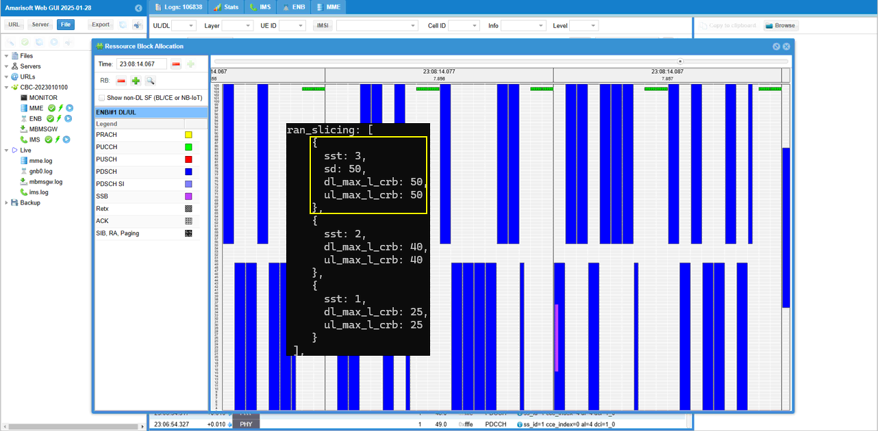
The new part in this test is ran_slicing.
ran_slicing defines radio resource behavior for each slice. In this example, each slice is given a maximum number of logical CRBs for downlink and uplink.
The slice sst 3 with sd 50 is configured with dl_max_l_crb 50 and ul_max_l_crb 50. This gives it the largest radio resource limit, so it can be treated as the highest priority slice in this example.
The slice sst 2 is configured with 40 CRBs for downlink and uplink.
The slice sst 1 is configured with 25 CRBs for downlink and uplink. This gives it the smallest radio resource limit, so it can be treated as the lower priority slice in this example.
So this test goes one step beyond basic NSSAI signaling. The gNB not only advertises supported slices, but also applies different radio resource limits per slice. This allows you to test whether traffic associated with a specific S-NSSAI is handled according to the configured RAN slicing rule.

Followings are the configurations in mme-ran-slice.cfg
Same as in gNB configuration, three network slices ({sst:1, sd:1}, {sst:2}, {sst:3, sd:50}) are configured for the CORE Network.
The nssai block defines the slices supported by the AMF or core network side. In this example, the supported slices are sst 1 with sd 1, sst 2, and sst 3 with sd 50.
This configuration should be aligned with the gNB slice configuration. The gNB side defines which slices are available from the RAN and tracking area point of view. The core network side defines which slices can be accepted and returned to the UE as Allowed NSSAI.
For this RAN slicing test, the core network still handles the NAS-level slice negotiation. It checks the Requested NSSAI from UEsim and sends the allowed slice information in Registration Accept.
The actual radio resource control per slice is handled by the gNB ran_slicing configuration, but the core network nssai configuration is still needed so that the requested slice can be accepted first.
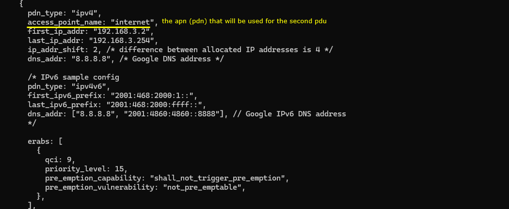
In this test, two different PDNs are prepared in the Callbox configuration.
The first PDN uses access_point_name default. This is the PDN used during the initial registration or initial attach procedure. No specific slice is configured directly under this PDN, so the network will associate it with the slice selected by the default registration behavior.
The second PDN uses access_point_name internet. This PDN is not the initial default PDN in this test. It will be created later by using Remote API. At that time, the user can explicitly specify which slice should be used for this additional PDU session.
Both PDNs use IPv4 and have separate IP address pools. The default PDN uses the 192.168.2.x range, while the internet PDN uses the 192.168.3.x range. This makes it easier to distinguish which PDU session is being used after the UE receives an IP address.
No slice-specific configuration is directly written inside these PDN blocks. So the key point of this test is not static PDN-to-slice mapping in the configuration file. Instead, the first PDN is created using the default slice behavior, and the second PDN is created later by Remote API with the slice selected by the user.

Followings are the configurations in ue-nr-sa.cfg In this test, I don't put any specific configuration for slices on UEsim since those configuration will be specified by RemoteAPI.
The configuration includes IMSI, authentication key, and UE capability-related parameters. However, there is no specific NSSAI or slice-related configuration in this UEsim file.
This is intentional for this test. The slice selection will not be fixed in the UEsim configuration. Instead, the slice information will be provided later through Remote API when the additional PDU session is created.
So, during the initial registration, UEsim behaves like a normal UE without a predefined slice preference in this file. After the UE is registered, Remote API is used to trigger the second PDU session and specify which S-NSSAI should be associated with that session.
This makes the test more flexible because you can change the slice used for the additional PDU session without modifying and restarting the UEsim configuration file.

Perform the Test
Start the test by checking the NR cell configuration on the Callbox.
The cell phy command shows the physical layer configuration of the gNB. In this example, the cell is running as NR Band n78 with 40 MHz bandwidth. The downlink and uplink ARFCN are both 632628, so this is a TDD cell. The subcarrier spacing is 30 kHz for both downlink and uplink. The SSB is configured at ARFCN 631968.
The cell command shows the higher-level cell configuration. It confirms that the cell belongs to PLMN 00101 and TAC 0x000064. The PCI is 500 and the PRACH sequence index is 1.
This step is a basic sanity check before testing RAN slicing. It confirms that the NR cell is active and configured as expected. After this, UEsim can attach to the cell, get the initial default PDU session, and then the second PDU session can be triggered later by Remote API with the desired slice configuration.

Power on UEsim and make sure that it can find the NR cell.
The power_on command starts the UE operation in UEsim. After that, UEsim begins cell search and reads the broadcast information from the gNB.
Cell 0: SIB found means that UEsim has successfully detected the cell and decoded the system information block. This confirms that the UE can see the cell and that the basic radio broadcast information is available.
This is the first checkpoint before registration. After SIB is found, UEsim can continue with random access, RRC setup, NAS registration, and initial PDU session establishment.
![]()
Once the initial attach process is complete, trigger the "internet" pdu with a specific slice configuration using the remoteAPI as follows.
|
./ws.js ue '{"message":"pdn_connect", "ue_id" : 1, "apn" : "internet", "snssai" : {"sst" : 3,"sd" : 50} }' |
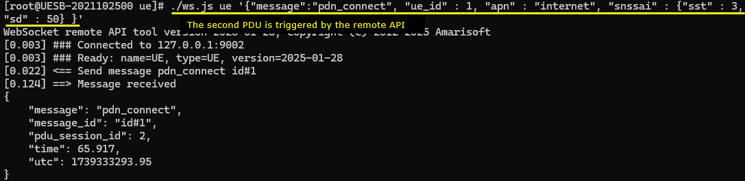
If the Remote API command has no syntax problem, UEsim returns a response like this.
The ws.js command sends pdn_connect to UEsim through the WebSocket remote API interface.
In this example, ue_id is 1, so the command is applied to UE 1. The apn is internet, so this command triggers a new PDU session for the internet DNN.
The important part is snssai. Here, sst is 3 and sd is 50. This means the second PDU session is requested with the network slice sst 3, sd 50.
The response shows message: pdn_connect and pdu_session_id: 2. This means UEsim accepted the command and started the second PDU session establishment procedure.
So this step confirms that the second PDU session is not created automatically from the static UEsim configuration. It is triggered dynamically by Remote API with the slice selected by the user.
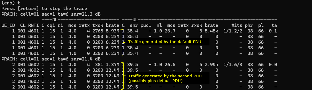
You can confirm the traffic for the two PDU session. (
You can use the enb t trace to confirm that traffic is being scheduled after the PDU sessions are established.
In this example, two groups of traffic activity are visible. The first group is interpreted as traffic generated by the initial default PDU session. The second group appears after the Remote API pdn_connect command, so it is interpreted as traffic related to the second PDU session, possibly together with remaining traffic from the default PDU.
The trace shows radio-level scheduling information such as bitrate, MCS, retransmission count, SNR, and uplink/downlink activity. This confirms that data is flowing through the radio interface.
However, this PHY layer trace alone does not explicitly tell which traffic belongs to which PDU session or which S-NSSAI. It only shows that the UE is transmitting and receiving data at the radio level.
So the interpretation here should be based on the test context. The first traffic activity is seen after the default PDU is created, and the second traffic activity is seen after the second PDU is triggered by Remote API with the selected S-NSSAI. To prove the exact mapping, you should check NAS, NGAP, GTP-U, or PDU session level logs together with this PHY trace.
In the mme screen, the ue command confirms whether the intended PDU sessions are established.
In this example, REG is Y, so the UE is registered to the 5GC. The #BEARER value is 2, which means two PDU sessions are active for this UE.
The IP_ADDR field shows two APN or DNN entries.
default/192.168.2.2 is the initial PDU session created with the default PDN.
internet/192.168.3.2 is the second PDU session created later by Remote API.
This confirms that the test created two separate PDU sessions as intended. The default PDU was established first during the normal registration procedure, and the internet PDU was added later by the pdn_connect Remote API command.

Log Analysis
In this section, I will show you only the portions of the log that are relavent to this tutorial. For the full log, refer to the sample log linked aboved.
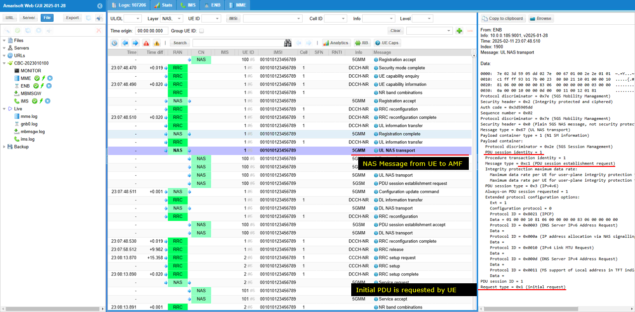
During the initial registration, the UE sends PDU Session Establishment Request to create the first PDU session.
This message is carried inside UL NAS Transport. UL NAS Transport means the UE is sending a NAS message toward the AMF.
Inside this UL NAS Transport, the actual 5GSM message is PDU Session Establishment Request. This is the message used by the UE to request a new PDU session.
In this log, Request type is initial request. This means the UE is asking the network to create the initial PDU session, not to modify or reconnect an existing one.
This first PDU session corresponds to the default PDN in this test. Later, the second PDU session is triggered separately by Remote API. So this log is the checkpoint for the initial UE-originated PDU session establishment during registration.
This log shows the PDU Session Establishment Request after it is extracted from the UL NAS Transport message.
In the previous step, the UE sent UL NAS Transport to the AMF. That UL NAS Transport contained the 5GSM PDU Session Establishment Request inside it.
Here, Amarisoft shows the extracted PDU Session Establishment Request as a separate NAS/5GSM message. This represents the session management message being handled toward the SMF side.
The message type is PDU session establishment request. This means the UE is requesting creation of a PDU session.
The PDU session identity is 1, so this is the first PDU session. The request type is initial request, which means this is a new PDU session setup.
In this test, this message corresponds to the initial default PDU session. The later second PDU session will be triggered separately by Remote API.
The network responds with PDU Session Establishment Accept.
This means the SMF accepted the UE request and created the first PDU session. In this example, the PDU session identity is 1, so this is the initial PDU session created during registration.
The network assigns IPv4 address 192.168.2.2 to the UE. This matches the IP pool of the default PDN.
The S-NSSAI IE shows SST 0x01. This means the first PDU session is associated with slice SST 1. In this test, this slice is selected by the network during the initial PDU session setup.
The DNN is shown as default.mnc001.mcc001.gprs. This indicates that the allocated PDU session is for the default APN or PDN.
So this log confirms that the initial default PDU session has been accepted by the network, assigned an IP address, and associated with the default slice SST 1.
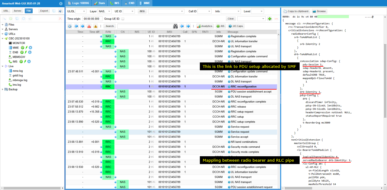
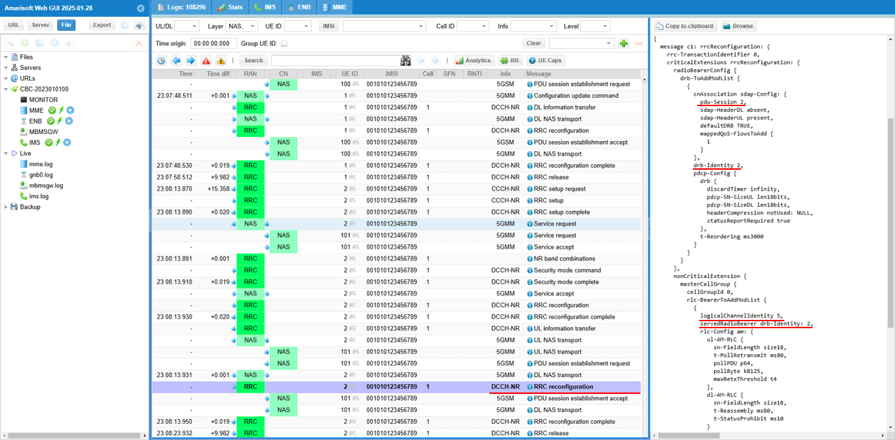
After the core network creates the PDU session, the gNB creates the corresponding DRB on the radio side.
The PDU Session Establishment Accept confirms that the core network has created the PDU session. But the UE still needs a radio bearer to carry the user-plane data over NR radio. This is done by RRC Reconfiguration.
In this RRC Reconfiguration message, pdu-Session links the radio configuration to the PDU session created by the core network. In this example, pdu-Session 1 means this DRB is associated with PDU session ID 1.
drb-Identity identifies the DRB created for this PDU session. Here, drb-Identity 1 is used.
servedRadioBearer connects the logical channel configuration to the DRB. In this example, servedRadioBearer is set to drb-Identity 1, so this logical channel is used for DRB 1.
logicalChannelIdentity identifies the logical channel used by this DRB. This is the RLC/MAC-side pipe used to carry the data for the radio bearer.
So this message shows the mapping chain from core network session to radio bearer. PDU session 1 is mapped to DRB 1, and DRB 1 is mapped to a logical channel. This is how the user-plane data from the core network is connected to the NR radio bearer.
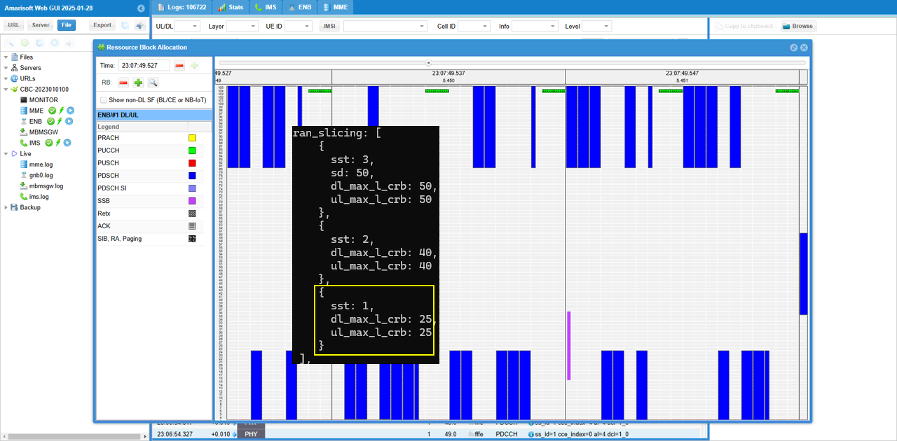
For this slice associated initial PDU session, the physical layer resources are allocated as shown below.
For the initial PDU session, the selected slice is SST 1.
In the RAN slicing configuration, SST 1 is configured with dl_max_l_crb 25 and ul_max_l_crb 25. This means the gNB limits the maximum radio resource allocation for this slice to 25 logical CRBs in downlink and 25 logical CRBs in uplink.
The resource block allocation view shows how physical layer resources are scheduled over time. The blue blocks represent PDSCH allocation, and the resource usage is constrained according to the RAN slicing rule applied to the selected slice.
So this screenshot shows the radio-side effect of the slice configuration. The PDU session is associated with SST 1, and the gNB applies the corresponding RAN slicing resource limit for that slice.
This is different from the earlier NAS-only slicing checks. Here, the slice is not only visible in NAS signaling, but also reflected in the physical layer resource allocation behavior at the gNB.
With the remoteAPI ./ws.js ue '{"message":"pdn_connect", "ue_id" : 1, "apn" : "internet", "snssai" : {"sst" : 3,"sd" : 50} }', following procedure is performed.
UE triggers a PDU session and request a specific network slice (SST 3, SD 50 in this case) and DNN "internet". The NAS message (PDU session establishment request in this case) is encapsulated by UL NAS Transport and is conveyed to AMF
In the log, the UE sends UL NAS Transport to the AMF. This UL NAS Transport carries the 5GSM PDU Session Establishment Request inside it.
The PDU session identity is 2, so this is not the initial PDU session. It is the second PDU session triggered by Remote API.
The decoded message shows DNN internet and S-NSSAI with SST 0x03 and SD 0x000032. This confirms that the UE is requesting the internet PDU session using the slice SST 3, SD 50.
So this step verifies that Remote API can dynamically trigger a new PDU session and specify which slice should be used for that PDU session.
The PDU session establishment request message is transferred to SMF (You see PDU session identity is 2 in this case) .
In the previous step, the UE sent the request inside UL NAS Transport toward the AMF. After that, the AMF extracts the 5GSM message and forwards the PDU Session Establishment Request to the SMF for session handling.
In this log, the message is shown as PDU session establishment request. The PDU session identity is 2, so this request is for the second PDU session.
This confirms that the Remote API triggered PDU session request has reached the session management side. The first PDU session was created during the initial registration, and this message is for the additional PDU session requested later with the internet DNN and the selected slice.
Core network respond with PDU session establishement accept allocating a specific NSSAI (SST=3, SD=50 in this case) which is associated with a specific DNN (internet.mnc001.mcc01.gprs in this case)
In this message, PDU session identity is 2. This confirms that the accepted session is the additional PDU session triggered by Remote API, not the initial default PDU session.
The network allocates S-NSSAI with SST 3 and SD 50. In the decoded message, SST is shown as 0x03 and SD is shown as 0x000032, which corresponds to decimal 50.
The DNN is internet.mnc001.mcc001.gprs. This means the accepted PDU session is associated with the internet DNN.
So this log confirms that the Remote API request was handled successfully. The UE requested the second PDU session with DNN internet and slice SST 3, SD 50, and the core network accepted the session with the same slice information.
This is PDU session establishement accept message extracted from the DL NAS transport. Basically the contents of the messages are same as in DL NAS transport.
In the previous step, the core network sent DL NAS Transport to the UE. That DL NAS Transport carried the 5GSM PDU Session Establishment Accept inside it.
Here, Amarisoft shows the extracted PDU Session Establishment Accept as a separate NAS or 5GSM message. The contents are basically the same as the PDU session information shown inside DL NAS Transport.
The PDU session identity is 2, so this message is for the second PDU session triggered by Remote API.
The S-NSSAI IE shows SST 0x03 and SD 0x000032. This means the accepted PDU session is associated with slice SST 3 and SD 50.
The DNN is internet.mnc001.mcc001.gprs, so this second PDU session is mapped to the internet DNN.
This confirms again that the second PDU session was accepted by the core network with the intended slice and DNN.
After the core network creates the second PDU session, the gNB creates another DRB for that session.
This is done by RRC Reconfiguration. The purpose of this message is to add the radio bearer that will carry the user-plane traffic for the new PDU session.
In this example, pdu-Session is set to 2. This links the radio bearer configuration to PDU session ID 2, which is the second PDU session triggered by Remote API.
drb-Identity is also set to 2. This means a new DRB is created for this second PDU session.
logicalChannelIdentity is set to 5, and servedRadioBearer points to drb-Identity 2. This means logical channel 5 is mapped to DRB 2, and DRB 2 is mapped to PDU session 2.
So the mapping chain is clear. PDU session 2 is connected to DRB 2, and DRB 2 is carried through logical channel 5. This is how the second PDU session, which was created with slice SST 3 and SD 50, gets its own radio bearer on the NR side.
For this slice-associated PDU session, the physical layer resources are allocated according to the RAN slicing configuration.
In this case, the PDU session is associated with SST 3 and SD 50. In the ran_slicing configuration, this slice is configured with dl_max_l_crb 50 and ul_max_l_crb 50.
This means the gNB can allocate up to 50 logical CRBs in downlink and up to 50 logical CRBs in uplink for traffic belonging to this slice.
The resource block allocation window shows the actual scheduled radio resources over time. The blue blocks represent PDSCH allocations. Compared with the SST 1 case, this slice has a larger configured CRB limit, so it can receive a larger amount of radio resources when traffic is available.
So this screenshot shows the RAN-side effect of the second PDU session. The second PDU session was created with SST 3 and SD 50, and the gNB applies the corresponding RAN slicing resource limit configured for that slice.
Test 5 : URSP - UEsim
This is to show on how to test URSP (Manage UE Policy Command) message. Main purpose of this test is to focus on the parameters and the syntax of remote API command for usrp and verify the corresponding NAS message sent out from the callbox(MME in this case)
Configuration
Use the same configuration as Test 2
Perform the Test
Start the test by checking the NR cell configuration on the Callbox.
The cell phy command shows that the gNB is running with PLMN 00101 and gNB ID 0x12345. The cell is configured as NR Band n78 with 20 MHz bandwidth.
The downlink and uplink ARFCN are both 632628, so this is a TDD cell. The subcarrier spacing is 30 kHz for both downlink and uplink. The SSB is configured at ARFCN 632544 with 30 kHz SCS.
This step is a basic sanity check before testing URSP signaling. URSP itself is not verified from this command. It only confirms that the NR cell is active and ready, so UEsim can register to the 5GC and later receive the Manage UE Policy Command from the network.
Power on UEand make sure that it attaches to the NR cell.
The enb t command shows the live radio trace from the gNB side. In this example, UE_ID 1 is connected to cell 001 and has C-RNTI 4601. This confirms that UEsim has established a radio connection with the gNB.
The DL and UL columns show active radio scheduling information, such as MCS, bitrate, retransmission count, SNR, and HARQ-related values. Since these values are being updated, the UE is actively communicating with the cell.
This step only confirms the basic UE attachment and radio activity. For the URSP test, the important NAS signaling comes later, after the UE is registered to the 5GC and the network sends the Manage UE Policy Command.
Confirm that UE completed the attach and get the IP address. If you don't get this including IP address, you need to troubleshoot. (
The ue command in mme shows the UE status from the core network side. In this example, REG is Y, so the UE is registered to the 5GC.
The bearer count is 1, and the IP_ADDR field shows internet/192.168.3.2. This means the internet PDU session has been established and the UE has received the IP address 192.168.3.2.
For the URSP test, also remember the SUPI and IMEI shown here. In this example, the SUPI is 001010123456789 and the IMEI is 0123456700000101.
These values are important because they are used in the Remote API command when triggering URSP policy delivery. If the SUPI or IMEI in the Remote API command does not match the registered UE, the policy may not be delivered to the intended UE.

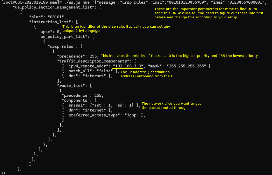
Now send a RemoteAPI command to send "Manage UE policy command" message. The message type is ursp_rules. This tells Amarisoft MME/5GC to generate URSP policy information and deliver it to the UE.
The imsi and imei fields are important because they identify the target UE. These values should match the SUPI and IMEI shown in the mme ue result. If these values are wrong, the network may not find the UE and the URSP rule will not be sent to the intended UE.
The plmn field specifies the PLMN where this UE policy section applies. In this example, it is 00101.
The ursp field is the identifier of the URSP rule. It is basically a unique 2-byte integer used to identify this rule.
The precedence field defines the priority of the URSP rule. Lower value means higher priority. So precedence 0 is the highest priority, and precedence 255 is the lowest priority.
The traffic_descriptor_components define what traffic this rule should match. In this example, the rule matches traffic going to IPv4 remote address 192.168.3.3 with mask 255.255.255.255. It also includes dnn internet, so the rule is related to traffic for the internet DNN.
The route_list defines how the matched traffic should be routed. In this example, the route component includes snssai with sst 1 and sd 1, dnn internet, and preferred_access_type 3gpp.
So this URSP rule tells the UE that traffic matching the specified destination and DNN should be routed using the internet DNN over 3GPP access with the slice sst 1, sd 1.
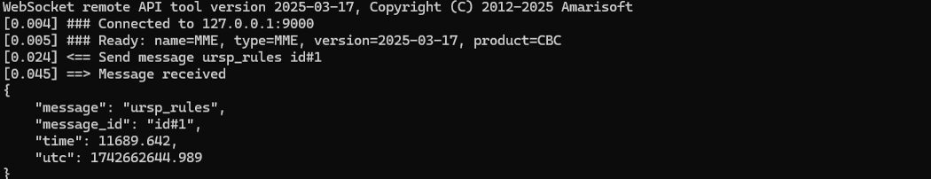
Following is the text version of the command so that you can copy and modify easily.
|
[root@CBC-2023010100 mme]# ./ws.js mme '{"message":"ursp_rules","imsi":"001010123456789", "imei":"01234567000001", "ue_policy_section_management_list": [ { "plmn": "00101", "instruction_list": [ { "upsc": 0, "ue_policy_part_list": [ { "ursp_rules": [ { "precedence": 255, "traffic_descriptor_components": [ { "ipv4_remote_addr": "192.168.3.3", "mask": "255.255.255.255" }, { "match_all": "false" }, { "dnn": "internet" }, ], "route_list": [ { "precedence": 255, "components": [ { "snssai": {"sst": 1, "sd": 1} }, { "dnn": "internet" }, { "preferred_access_type": "3gpp" }, ], }, ], }, ], }, ], }, ], } ], }' WebSocket remote API tool version 2025-03-17, Copyright (C) 2012-2025 Amarisoft [0.004] ### Connected to 127.0.0.1:9000 [0.005] ### Ready: name=MME, type=MME, version=2025-03-17, product=CBC [0.024] <== Send message ursp_rules id#1 [0.045] ==> Message received { "message": "ursp_rules", "message_id": "id#1", "time": 11689.642, "utc": 1742662644.989 } |
Log Analysis
In this section, I will show you only the portions of the log that are relavent to this tutorial. For the full log, refer to the sample log linked above.
After the ursp_rules Remote API command is processed correctly, the Callbox core network sends DL NAS Transport to the UE. This downlink NAS message carries the Manage UE Policy Command inside it.
The Manage UE Policy Command is the actual NAS message used to deliver the URSP rule to the UE. So you do not need to check many different NAS messages for this test. The key point is to confirm that DL NAS Transport is generated and that its payload contains Manage UE Policy Command.
In the decoded message, you can see UE policy section management list. This corresponds to the URSP rule that was configured in the Remote API command.
The decoded URSP contents show the traffic descriptor and route selection information. The traffic descriptor includes the IPv4 remote address, the match-all setting, and the DNN internet. The route selection descriptor includes the S-NSSAI with SST 1 and SD 1, the DNN internet, and the preferred access type as 3GPP access.
This confirms that the Remote API command was converted into a NAS Manage UE Policy Command and sent from the Callbox core network to the UE.
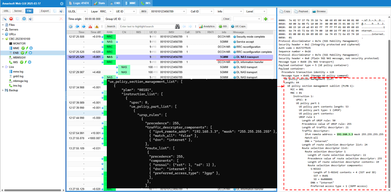
RRC / NAS Signaling
DL NAS Transport/Manage UE policy Command
: This is the RegistrationRequest message sent by UE to inform the network slice configuration it wants (
Protocol discriminator = 0x7e (5GS Mobility Management)
Security header = 0x2 (Integrity protected and ciphered)
Auth code = 0xd6af39a6
Sequence number = 0x0c
Protocol discriminator = 0x7e (5GS Mobility Management)
Security header = 0x0 (Plain 5GS NAS message, not security protected)
Message type = 0x68 (DL NAS transport)
Payload container type = 5 (UE policy container)
Payload container:
Procedure transaction identity = 128
Message type = 0x01 (Manage UE policy command)
UE policy section management list:
Length: 64
UE policy section management sublist (PLMN 1):
MCC = 001
MNC = 01
Instruction 1:
UPSC: 0
UE policy part 1
UE policy part contents length: 53
UE policy part type: 1 (URSP)
UE policy part contents:
URSP rule 1
Length of URSP rule: 50
Precedence value of URSP rule: 255
Length of traffic descriptor: 21
Traffic descriptor:
IPv4 remote address = 192.168.3.2 mask 255.255.255.255
Match-all
DNN = "internet"
Length of route selection descriptor list: 24
Route selection descriptor list:
Route selection descriptor 1
Length of route selection descriptor: 22
Precedence value of route selection descriptor: 255
Length of route selection descriptor contents: 19
Route selection descriptor components:
S-NSSAI
Length of S-NSSAI contents = 4 (SST and SD)
SST = 0x01
SD = 0x000001
DNN = "internet"
Preferred access type = 1 (3GPP access)