
NR SA LTM(L1/L2 Triggered Mobility)
This tutorial shows how to test NR SA to NR SA L1/L2 Triggered Mobility (LTM). This tutorial also shows how to configure LTM candidate cells and measurement reporting, and how to trigger the measurement report and cell switch. LTM is a connected-mode mobility procedure in which the target-cell configuration is prepared through RRC signaling in advance, while the actual cell switch is triggered using faster L1/L2 signaling, as described below.
Step 1 : Network (gNB) configures the UE with the measurement configuration, LTM candidate cells, and the required target-cell configurations
Step 2 : UE continuously performs the configured measurements and sends a measurement report when the configured reporting condition is satisfied
Step 3 : Network selects a target cell based on the measurement report and other mobility criteria
Step 4 : Network sends an L1/L2 mobility command to instruct the UE to switch to the selected target cell
Step 5 : UE applies the previously configured target-cell parameters, accesses the target cell, and completes the mobility procedure
In terms of frequencies of current cell and target/destination cell, the handover can be categorized into two types as below
- Intra Frequency Handover : Current Cell and Target Cell frequency is same
- Inter Frequency Handover : Current Cell and Target Cell frequency is different
Table of Contents
Introduction
5G New Radio (NR) Standalone (SA) networks introduce advanced connected-mode mobility procedures to support seamless user experience and maintain robust connectivity as User Equipment (UE) moves across different cells. Among these, L1/L2 Triggered Mobility (LTM) is a cutting-edge mechanism that leverages lower-layer signaling for faster and more efficient handovers. In the LTM procedure, the network (gNodeB or gNB) prepares the UE in advance with candidate cell configurations and measurement parameters via Radio Resource Control (RRC) signaling. The actual cell switch is then triggered using rapid Layer 1/Layer 2 (L1/L2) commands, reducing handover latency and improving mobility performance. This approach contrasts with traditional RRC-based handovers, where the entire process relies on higher-layer signaling, often resulting in increased delay. LTM plays a crucial role in high-mobility scenarios and dense network deployments by enabling the UE to rapidly transition between cells with minimal service interruption. This tutorial provides a hands-on guide to testing NR SA to NR SA LTM, including the configuration of measurement reporting, LTM candidate cells, and the triggering process for measurement reports and cell switches. By understanding the architectural principles and operational workflow of LTM, practitioners can effectively evaluate and optimize mobility performance in 5G NR networks.
-
Context and Background
- 5G NR SA networks are designed for enhanced mobility, ultra-reliable low-latency communications (URLLC), and massive connectivity.
- LTM introduces a split between RRC-based preparation and L1/L2-based execution to minimize handover interruption times.
- The gNB manages UE mobility by configuring candidate cells and measurement conditions, and by issuing fast-switch commands at the L1/L2 layers.
-
Relevance and Importance
- LTM is vital for supporting seamless mobility in high-speed scenarios such as highways, railways, and ultra-dense urban environments.
- By pre-configuring target cell parameters, LTM drastically reduces the time required for handover execution compared to legacy methods.
- Understanding and testing LTM is essential for network engineers, system integrators, and researchers working on 5G NR deployment and optimization.
-
Tutorial Outcomes
- Learn how to configure LTM candidate cells and measurement reporting in a 5G NR SA environment.
- Gain insights into triggering measurement reports and executing L1/L2-based mobility commands.
- Understand the distinction between intra-frequency and inter-frequency handovers in the context of LTM.
- Acquire practical skills for testing and validating LTM procedures using relevant tools and test equipment.
-
Prerequisite Knowledge and Skills
- Familiarity with 5G NR architecture, including the roles of gNB, UE, and core network components.
- Understanding of mobility concepts such as handover, measurement reporting, and cell reselection.
- Basic knowledge of RRC, L1/L2 signaling, and 5G NR protocol stack operations.
- Experience with network testing tools and simulation environments is recommended for hands-on exercises.
Summary of the Tutorial
This tutorial demonstrates test procedures for L1/L2 Triggered Mobility (LTM) between two NR SA (StandAlone) cells using the Amarisoft system. Three main tests are described: Test 1 (basic LTM4 procedure), Test 2 (LTM4 with additional Layer 3 measurement control), and Test 3 (LTM4 with early downlink synchronization). The procedures involve configuring two NR cells, preparing the UE and gNB for LTM, and executing mobility by directly changing cell power to trigger the handover.
-
Test Setup
- Two NR cells (serving and target) are configured on the same frequency band (n78), supporting 2x2 MIMO and TDD operation.
- SIM card and configuration files provided; advanced configuration available in the referenced Configuration Guide.
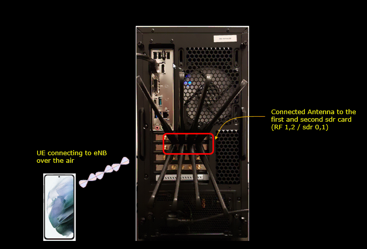
- Test setups A and B illustrate different hardware combinations (real UE, simulated UE).
-
Key Configuration Parameters
- LTM-related configuration parameters are highlighted, including measurement triggers, reporting quantities, switching thresholds, and candidate cell preparation.
- Important parameters include:
- Trigger conditions (activation_trigger, a3_report_type, a3_offset, a4/a5 thresholds, hysteresis, time_to_trigger)
- Reporting setup (periodic, type, quantity, period)
- LTM candidate list and target configurations
-
Test 1: SA Intra Frequency - LTM4
-
Configuration Procedure
- Configure gNB and UE using provided configuration files with LTM enabled and CONDITIONAL_HO disabled.
- Set N_CELL=2 for a two-cell scenario, N_ANTENNA_DL=2 for MIMO, and prepare both cells as LTM candidates of each other.
- For the serving cell:
- Set configuration_trigger: "immediate" to pre-configure the UE with candidate cell information.
- Enable periodic measurement reporting (quantity: ssb_Index_RSRP, period: 80ms).
- Switching condition: ltm4 threshold of -55dBm, count=2 (condition met twice before mobility command issued).
- Candidate list: specifies the pre-configured target cell and radio parameters.
- For the target cell:
- Symmetric configuration with the serving cell, allowing bidirectional LTM testing.
- Csi_resource_type: "csi_ssb" used for candidate evaluation and switching.
- Precoding and SSB configuration allow per-beam measurement and switching analysis.
- Common NR cell parameters are set (subcarrier spacing, bandwidth, TDD pattern).
- UE configured for two NR cells, TDD mode, 20MHz bandwidth, single simulated UE with LTM support enabled.
-
Test Execution Steps
- Start with serving cell at higher power (dl_gain = 0dB), candidate at lower power (dl_gain = -20dB).
- Reverse cell powers (serving to -20dB, candidate to 0dB) to trigger LTM condition.
- UE detects new candidate as stronger, meets LTM4 threshold in two consecutive reports, and triggers LTM mobility.
- Network sends L1/L2 mobility command, UE switches to the target cell, and resumes operation.
-
Log Analysis
- UE capability signaling confirms support for NR band n78 and LTM features.
- Measurement configuration and reporting confirm correct setup of SSB-based measurements and gap handling.
- MAC/PHY logs show LTM triggering, cell switch command transmission, context handling, and successful resumption on the target cell.
-
Configuration Procedure
-
Test 2: SA Intra Frequency - LTM4 and L3 Measurement
-
Configuration Procedure
- Similar two-cell setup as Test 1, but with explicit Layer 3 measurement control added in the configuration.
- Layer 3 measurements (A2 and A3 events) are configured in meas_config_desc:
- A2 event detects serving cell degradation (RSRP falls below threshold).
- A3 event detects neighbor cell becoming better than serving cell by a configured offset.
- Measurement gaps are configured as needed for inter-frequency scenarios.
- LTM candidate preparation and reporting are configured as in Test 1.
-
Test Execution Steps
- Initial downlink power conditions confirmed (serving stronger than candidate).
- Powers reversed to trigger measurement events:
- A2 event triggers measurement report when serving cell degrades.
- A3 event triggers report when candidate cell improves.
- Measurement gap configuration ensures UE can perform necessary measurements.
- Upon satisfying LTM4 (L1) condition, network triggers LTM Cell Switch Command.
- UE switches to target cell, applies pre-configured candidate settings, and confirms switch by sending RRC Reconfiguration Complete on the new cell.
-
Log Analysis
- UE capability signaling and measurement reports confirm correct event handling (A2/A3), measurement gap usage, and candidate evaluation.
- Advance preparation of target UE context demonstrated (pre-allocating resources and configuration before cell switch).
- CSI reporting and candidate configuration logs show mapping of SSB resources and TCI states for beam-based switching.
- MAC/PHY logs confirm successful triggering, execution, and completion of LTM mobility.
-
Configuration Procedure
-
Test 3: SA Intra Frequency - Early DL Sync
-
Configuration Procedure
- Same two-cell intra-frequency setup as Test 1, but the gNB uses gnb-ltm-early-dl-sync.cfg instead of gnb-sa-ltm.cfg.
- An early_dl_sync block is added inside the ltm section of each cell, guarded by the EARLY_DL_SYNC preprocessor option.
- early_dl_sync defines the condition that triggers the Candidate Cell TCI Activation MAC CE, and this is the only configuration difference from Test 1.
- Its ltm4 condition uses threshold -55 dBm with count 1, so the MAC CE is sent on the first evaluation that meets the threshold.
- The cell_switch ltm4 condition keeps threshold -55 dBm with count 2, so the actual switch still waits for a second evaluation.
- The UE therefore activates the prepared candidate TCI state and starts downlink synchronization before the cell switch command arrives.
- The remaining LTM parameters are unchanged from Test 1: configuration_trigger "immediate", periodic ssb_Index_RSRP reporting with period 80 ms, candidate_list pointing at the other cell, and ltm_target using csi_resource_type "csi_ssb".
- meas_config_desc contains only the A1, A2 and A3 RSRP conditions. No nr_ltm block is configured there, so candidate preparation is not gated by a Layer 3 event as it was in Test 2.
- Common cell parameters use 30 kHz subcarrier spacing and 20 MHz bandwidth, with two downlink antennas and one uplink antenna. The TDD pattern uses a 5 ms period with seven downlink slots, two uplink slots and one special slot.
- The UE uses ue-nr-sa-ltm.cfg with as_release 18, ltm_support true and rrc_initial_selection false, and defines both cells on rf_port 0 (ARFCN 625400) and rf_port 1 (ARFCN 626400).
-
Test Execution Steps
- cell_phy confirms the intra-frequency setup: cell 0x001 on 625400 and cell 0x002 on 626400, both in band n78 with 20 MHz and 30 kHz subcarrier spacing.
- Initial power condition is cell 0x001 (PCI 501) at dl_gain 0.0 dB and cell 0x002 (PCI 502) at dl_gain -20.0 dB.
- cell_gain 1 -20 and cell_gain 2 0 reverse the two power levels and create the LTM triggering condition.
- The UE trace shows the switch from cell 0x00 with RNTI 4601 to cell 0x01 with RNTI 4602, and RSRP improving from about -58.8 dBm to about -37.1 dBm.
-
Log Analysis
- UE capability signaling confirms band n78 support, ltm-MCG-IntraFreq-r18, ltm-InterFreq-r18, and ltm-MAC-CE-JointTCI-r18 with qcl-Resource-r18 set to ssb and Joint TCI limits of eight per cell and eight across cells.
- RRC reconfiguration sets the measurement object on ssbFrequency 625400 with smtc1 sf20: 0. A later message sets up a 6 ms measurement gap repeating every 40 ms, using gapOffset 4 and mgta ms0dot5.
- The LTM CSI report configuration is periodic with reportSlotConfig slots80: 29 on PUCCH resource 14 of uplink BWP 0, and it references LTM CSI resource configuration 0.
- Candidate 1 is added with PCI 502 and ssb-Frequency-r18 626400, and its prepared spCellConfig carries physCellId 502, absoluteFrequencyPointA 625788 and carrierBandwidth 51.
- Four Joint TCI states (0 to 3) are prepared with qcl-Type-r18 typeD, each referencing the SSB of the same index. Four NZP CSI-RS resources are grouped into resource set 1 with trs-Info true.
- The Candidate Cell TCI States Activation/Deactivation MAC CE appears while the UE is still on cell 1 with RNTI 0x4601. It carries Candidate ID 1 and Codepoint 1 selecting DL or Joint TCI State 3, which is the early downlink synchronization step this test adds.
- The LTM trigger entry follows, and the LTM Cell Switch Cmd is transmitted 5 ms later with Target Config ID 0 and TCI state ID 3.
- The Timing Advance Command reports that no valid timing adjustment is available, so the UE still performs random access on the destination cell.
- PRACH on cell 2 uses sequence_index 2 and ssb_index 3, the RAR returns rapid 2, the connection resumes with mac_crnti 0x4602, and RRC reconfiguration complete is received on cell 2.
-
Configuration Procedure
Overall Test Methodology:
- Configure two NR SA cells and a compliant UE (real or simulated) for LTM testing, ensuring both cells can serve as LTM candidates for each other.
- Pre-configure LTM candidate cell information in the UE using "immediate" configuration trigger for fast Layer 1/2 mobility execution.
- Set up measurement reporting and LTM4 switch conditions (threshold and count) to make the handover decision robust against short-term fluctuations.
- Use explicit Layer 3 measurement events (A2, A3) in advanced scenarios to control when LTM candidate preparation is activated.
- Use a separate early_dl_sync condition with a lower count than the cell_switch condition so that the Candidate Cell TCI Activation MAC CE is sent before the switch command.
- Perform stepwise power adjustments to trigger the mobility conditions and observe the UE's response and network handling through logs and traces.
- Verify successful mobility by checking RSRP before/after handover, RNTI changes, and log indications of context movement and random access on the new cell.
Test Setup
Test setup for this tutorial is as shown below.
- SIM Card used in this tutorial is the one delivered with the system as it is.
- If you want to change the configuration, The tutorial Configuration Guide would help
< Setup A >
< Setup B >
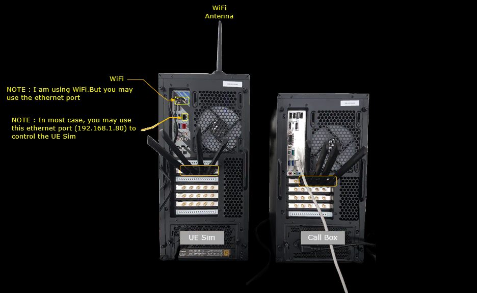
Key Configuration Parameters
The following are important L1/L2 Triggered Mobility (LTM) configuration parameters for this tutorial. Click an item to open its description in the Amarisoft documentation.
Test 1 : SA Intra Frequency - LTM4
In this test, I will show a simple scenario for triggering L1/L2 Triggered Mobility between two NR SA cells. The mobility is triggered by directly changing the cell power, causing the UE measurement result to satisfy the configured condition. The UE sends a measurement report, and the network then triggers the UE to switch to the selected target cell using L1/L2 signaling.
Configuration
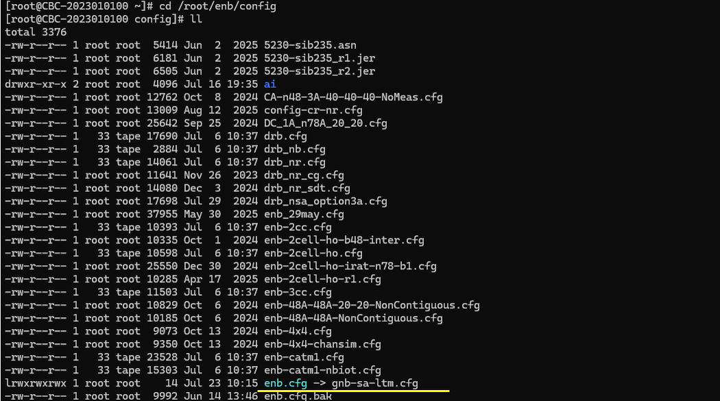
I used the gnb-sa-ltm.cfg which is copied and modified from gnb-sa.cfg
I also used mme-ims.cfg as it is.

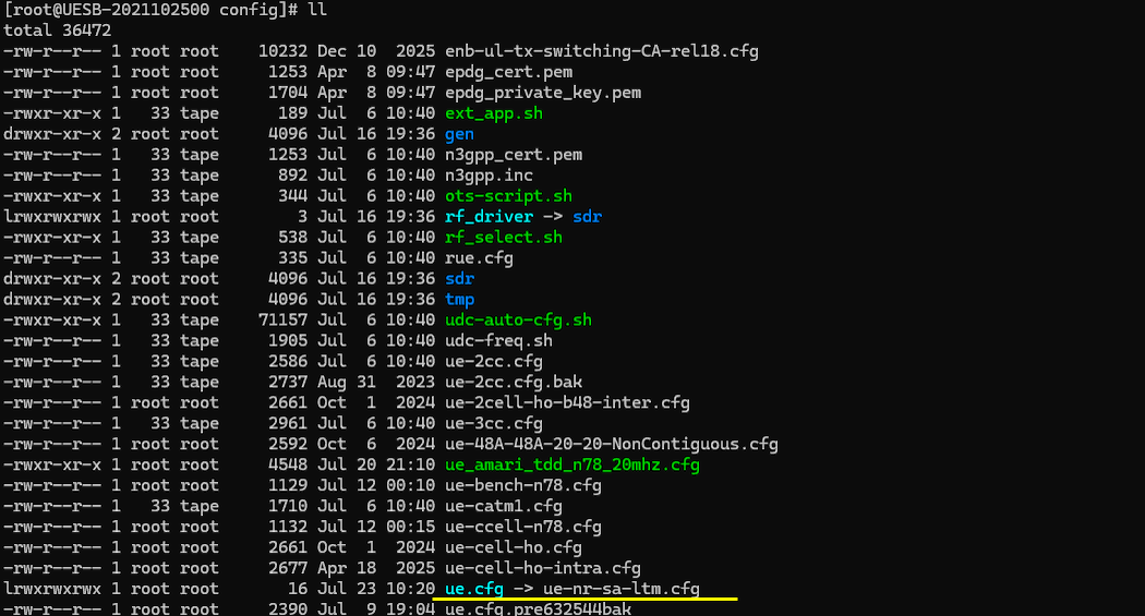
I used the ue-nr-sa-ltm.cfg which is copied and modified from ue-nr-sa.cfg
Configure gnb-sa-ltm.cfg as below.
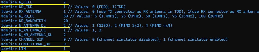
This configuration enables a two-cell NR SA LTM test scenario. N_CELL is set to 2 to create the serving and target cells, and N_ANTENNA_DL is set to 2 to configure 2×2 MIMO transmission. CONDITIONAL_HO is disabled because this test uses L1/L2 Triggered Mobility rather than Conditional Handover, while LTM is enabled to activate the LTM-specific configuration and procedure.
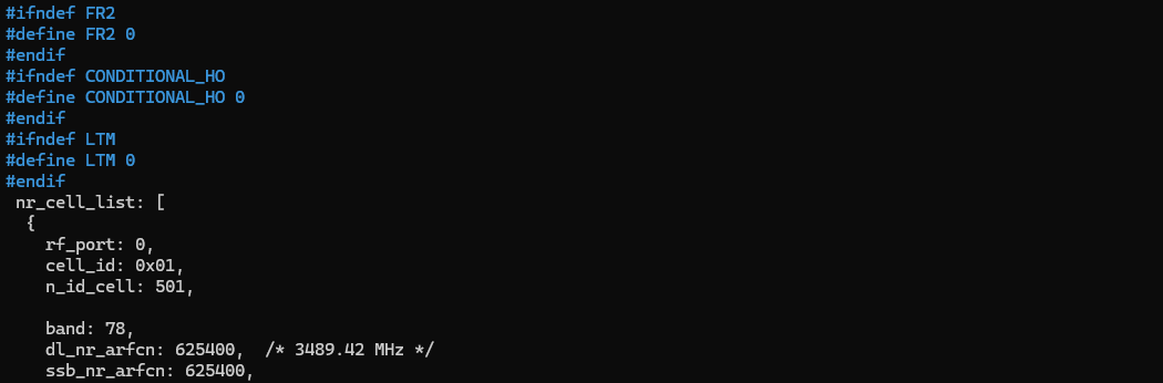
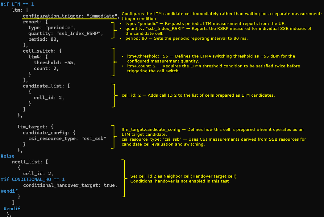
This configuration defines the LTM relationship between the two NR cells. Cell 1 is configured as the serving cell, while cell 2 is prepared in advance as an LTM candidate target. The preprocessor first assigns default values of 0 to FR2, CONDITIONAL_HO, and LTM when those variables are not explicitly defined. Because LTM is enabled for this test, the LTM-specific configuration is included instead of relying only on the conventional neighbor-cell configuration.
Within the serving-cell configuration, configuration_trigger: "immediate" instructs the gNB to prepare and configure the LTM candidate without waiting for an additional measurement event to occur first. This allows the UE to receive the candidate-cell configuration in advance, so that the later mobility execution can be triggered through L1/L2 signaling with less RRC processing at the time of the cell switch.
The report section configures periodic measurement reporting. The quantity ssb_Index_RSRP requests RSRP measurements for the individual SSB indexes detected from the candidate cell, rather than only a single cell-level measurement value. The period value of 80 configures the UE to send these reports every 80 ms. These periodic reports allow the serving gNB to continuously evaluate the radio quality of the prepared candidate cell and determine whether the configured LTM switching condition has been satisfied.
The cell_switch section defines the condition used for LTM execution. The ltm4 condition uses a threshold of -55 dBm for the configured measurement quantity. The count value of 2 requires the threshold condition to be satisfied in two measurement evaluations before the switch is triggered. This prevents a single short measurement fluctuation from immediately causing the UE to change cells. Once the condition is satisfied for the required count, the network can send the corresponding L1/L2 mobility command to move the UE to the selected candidate.
The candidate_list identifies cell_id 2 as the cell prepared for LTM from cell 1. The detailed radio and access parameters required for the UE to access cell 2 are therefore provided before the actual mobility command. On the target-cell side, ltm_target marks cell 2 as a cell that can operate as an LTM candidate. The candidate_config section selects csi_resource_type: "csi_ssb", meaning that candidate evaluation and switching are based on CSI measurement resources associated with SSB transmission.
The alternative ncell_list block is used when LTM is disabled. In that case, cell 2 is configured only as a normal neighbor cell. The conditional_handover_target parameter is included only when CONDITIONAL_HO is enabled, so it has no effect in this LTM test. Therefore, this configuration clearly separates the LTM procedure from the conventional Conditional Handover procedure while allowing the same two-cell setup to support either test through the preprocessor options.
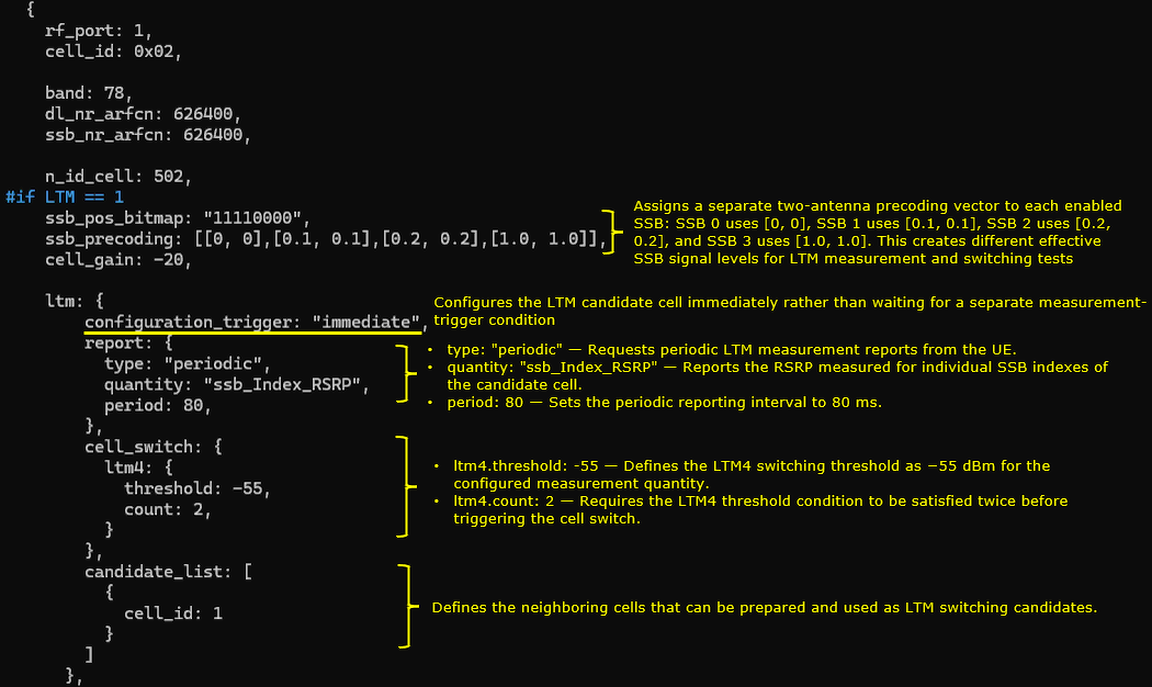
This block configures cell 2, identified by cell_id 0x02 and physical cell ID 502, as the second NR cell in the two-cell LTM test. It operates on NR band n78 with DL-ARFCN and SSB-ARFCN set to 626400. Since this cell is configured symmetrically with cell 1, it can operate either as the current serving cell or as the prepared LTM target, depending on the UE’s present connection and the direction of mobility.
The ssb_pos_bitmap value enables four SSB positions. The ssb_precoding configuration assigns a different two-antenna precoding vector to each enabled SSB. SSB 0 is transmitted mainly through the first antenna, SSB 1 uses a balanced combination of both antennas, SSB 2 is transmitted mainly through the second antenna, and SSB 3 again uses both antennas with equal weighting. This creates different effective SSB signal levels at the UE, allowing the test to verify SSB-index-specific RSRP reporting and to evaluate how LTM reacts when the quality of a particular SSB changes. The cell_gain value of -20 dB initially reduces the overall signal level of cell 2, so its power can later be increased to satisfy the configured LTM switching condition.
The ltm block defines the LTM operation when cell 2 is the serving cell. configuration_trigger: "immediate" causes the gNB to provide the candidate-cell configuration without waiting for a separate measurement-trigger event. As a result, the UE is prepared in advance with the information required to switch from cell 2 to cell 1. This advance preparation is one of the main differences between LTM and a conventional RRC-based handover, because the final mobility execution can be initiated through lower-layer signaling without sending the full target configuration at the switching moment.
The report section requests periodic measurement reporting using ssb_Index_RSRP. This quantity reports the RSRP measured for individual SSB indexes, which is important in this test because the enabled SSBs use different precoding vectors and may therefore be received with different power levels. The period value of 80 configures the reporting interval to 80 ms. These periodic reports provide the serving gNB with frequent updates about the SSB-level radio quality of the candidate cell.
The cell_switch section defines the LTM4 execution condition. The threshold is set to -55 dBm, meaning that the relevant candidate-cell measurement must reach the configured threshold before the switching condition is considered satisfied. The count value of 2 requires the condition to be met twice before the cell switch is triggered. This provides basic filtering against a temporary measurement spike and avoids triggering mobility based on a single isolated report.
The candidate_list identifies cell_id 1 as the LTM candidate for cell 2. Therefore, when the UE is connected to cell 2, cell 1 is prepared as the possible target cell. Together with the corresponding configuration in cell 1, this creates a bidirectional LTM relationship: cell 1 can switch to cell 2, and cell 2 can switch back to cell 1.
The ltm_target section defines how cell 2 is prepared when it is used as an LTM target by the other cell. The candidate_config selects csi_resource_type: "csi_ssb", indicating that SSB-based CSI resources are used for candidate-cell evaluation and switching. This matches the ssb_Index_RSRP reporting configuration and allows the network to evaluate the candidate using measurements associated with the configured SSB resources.
When LTM is disabled, the configuration falls back to the ncell_list block. In that case, cell 1 is configured only as a normal neighboring cell. The conditional_handover_target parameter is enabled only when CONDITIONAL_HO is separately set to 1. Since Conditional Handover is disabled in this test, that parameter is not applied, and the mobility procedure is controlled exclusively by the LTM configuration.
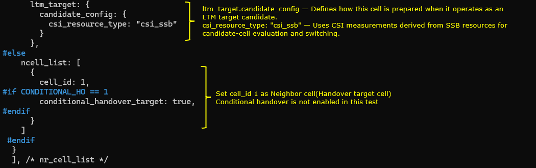
This block(nr_cell_default) defines the common radio configuration for both NR cells. It uses 30 kHz subcarrier spacing, 20 MHz bandwidth, two downlink antennas, and one uplink antenna. For TDD operation, the default pattern uses a 5 ms period with seven downlink slots, two uplink slots, and one special slot containing six downlink symbols and one uplink symbol.
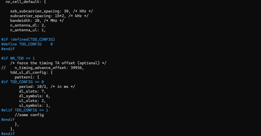
The csi_rs block configures the CSI reference-signal resources and CSI reporting. Inside resource_auto, nzp_csi_rs_period is set to 80 ms for NZP-CSI-RS transmission. When LTM is enabled, ssb_set is set to true to include an SSB-related CSI resource set for candidate-cell beam measurement. Inside csi_report_config, report_config_type is set to periodic, period is set to 80 ms, and report_quantity is set to CRI_RI_PMI_CQI. For FR2, trs_presence is set to false, so TRS is not included in the resource_auto configuration.
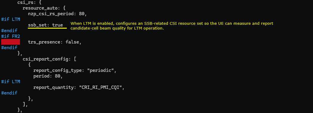
The meas_config_desc block defines the general NR measurement configuration. It includes A1, A2, and A3 RSRP-based measurement conditions for normal measurement reporting and conventional handover operation. In this LTM test, the nr_ltm block is not configured inside meas_config_desc. Therefore, LTM candidate preparation is not controlled by a separate Layer 3 measurement-trigger condition. The candidate configuration is provided immediately by the gNB, and the actual cell switch is evaluated using the configured LTM Layer 1 measurement condition.
The nr_conditional_handover block is included only when CONDITIONAL_HO is set to 1 and is not used in this test. The meas_gap_config block sets pattern_id to 0, configuring the measurement-gap pattern available for inter-frequency or other measurements that require measurement gaps.

Configure ue-nr-sa-ltm.cfg as below
N_CELL is set to 2, NR_TDD is set to 1 for TDD operation, and CELL_BANDWIDTH is set to 20 MHz. N_ANTENNA_DL is set to 2 for 2x2 downlink MIMO, while N_ANTENNA_UL is set to 1. UE_COUNT is set to 1, and CHANNEL_SIM is set to 0 because the channel simulator is not used in this test.

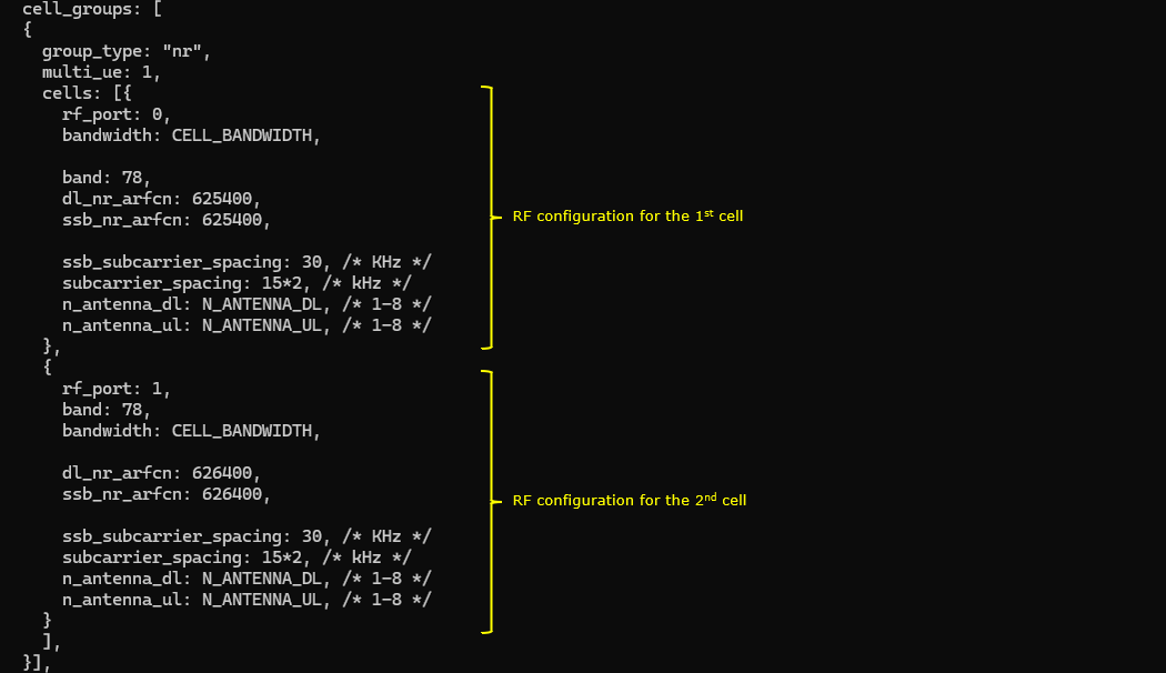
The cell_groups block defines one NR cell group containing the RF configurations for both cells used in the LTM test. The parameter group_type is set to nr, and multi_ue is set to 1.
Inside the cells block, the first cell uses rf_port 0, band 78, dl_nr_arfcn 625400, and ssb_nr_arfcn 625400. The second cell uses rf_port 1, band 78, dl_nr_arfcn 626400, and ssb_nr_arfcn 626400. Both cells use the bandwidth defined by CELL_BANDWIDTH, 30 kHz SSB and data subcarrier spacing, and the antenna numbers defined by N_ANTENNA_DL and N_ANTENNA_UL.
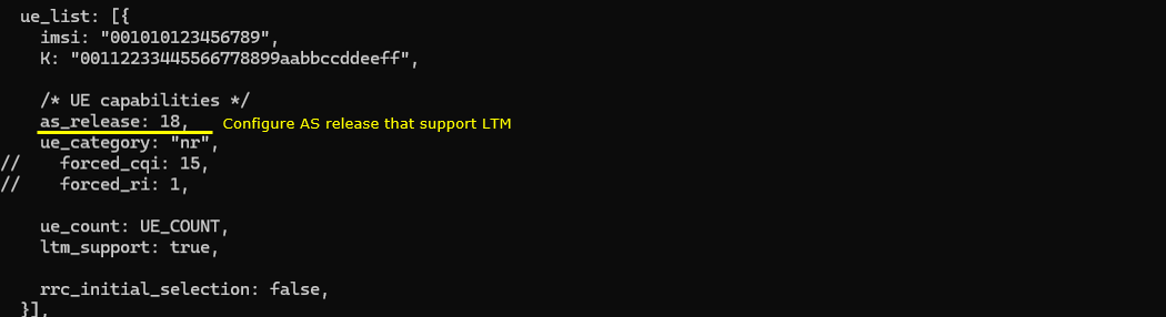
The ue_list block defines the simulated UE identity and capability settings used for the LTM test. The parameter as_release is set to 18 so that the UE advertises an NR access-stratum release that supports LTM. The parameter ue_category is set to nr, ue_count uses the value defined by UE_COUNT, and ltm_support is set to true to enable LTM capability in the simulated UE. The parameter rrc_initial_selection is set to false so that the UE does not perform automatic initial cell selection based on the strongest detected cell.
Perform the test
The cell_phy command displays the physical-layer configuration of the two NR cells used in the LTM test. Cell 0x001 uses dl_nr_arfcn 625400 and ssb_nr_arfcn 625400, while cell 0x002 uses dl_nr_arfcn 626400 and ssb_nr_arfcn 626400. Both cells operate in band n78 with 20 MHz bandwidth and 30 kHz subcarrier spacing. Since both ARFCNs belong to the same NR band, this is an intra-frequency LTM scenario.

The cell command first confirms the initial downlink power condition. Cell 0x001 with PCI 501 has dl_gain set to 0.0 dB and acts as the serving cell, while cell 0x002 with PCI 502 has dl_gain set to -20.0 dB and is initially weaker.
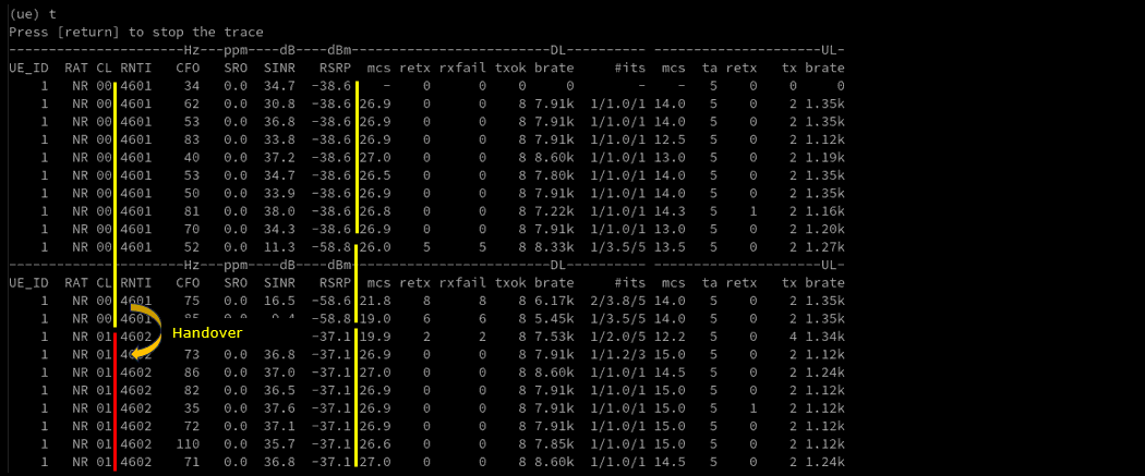
The cell_gain 1 -20 command reduces the dl_gain of cell 0x001 to -20 dB, and the cell_gain 2 0 command increases the dl_gain of cell 0x002 to 0 dB. This reverses the relative received power of the two cells and creates the triggering condition for LTM. The UE then detects cell 0x002 as the stronger candidate and the configured LTM measurement condition can be satisfied.

The UE trace shows the LTM cell switch from cell 0x00 with RNTI 4601 to cell 0x01 with RNTI 4602. Before the switch, the UE remains connected to the original serving cell while its RSRP decreases to approximately -58.8 dBm. After the configured LTM condition is satisfied, the UE changes to the target cell and receives the new RNTI 4602. The RSRP then improves to approximately -37.1 dBm, confirming that the UE has completed the L1/L2 triggered mobility procedure and is operating on the stronger target cell.
Log Analysis
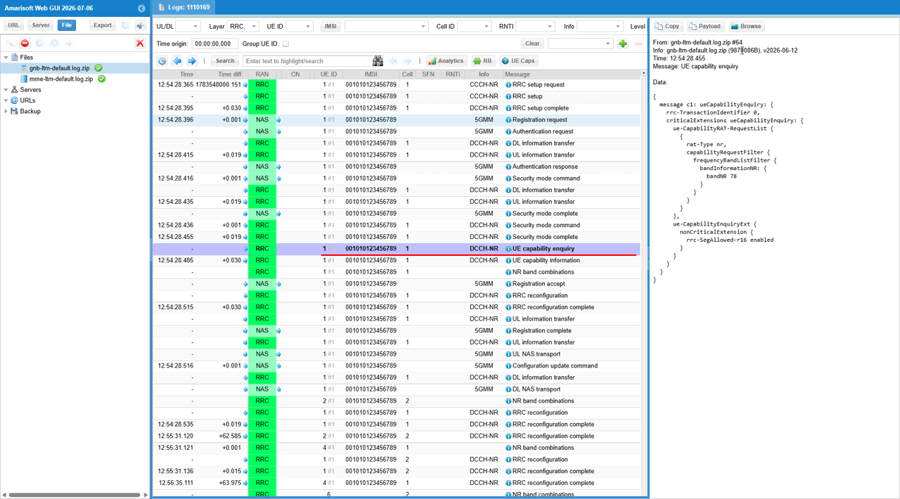
The UE capability enquiry message is sent by the gNB after the security procedure to request the UE radio capability required for the LTM test. In the ueCapabilityEnquiry block, rat-Type is set to nr, and frequencyBandListFilter specifies bandNR 78 so that the UE reports its NR capabilities for band n78. The nonCriticalExtension block includes rrc-SegAllowed-r16 enabled, indicating that segmented RRC capability transfer is supported when the UE capability information is too large for a single message.
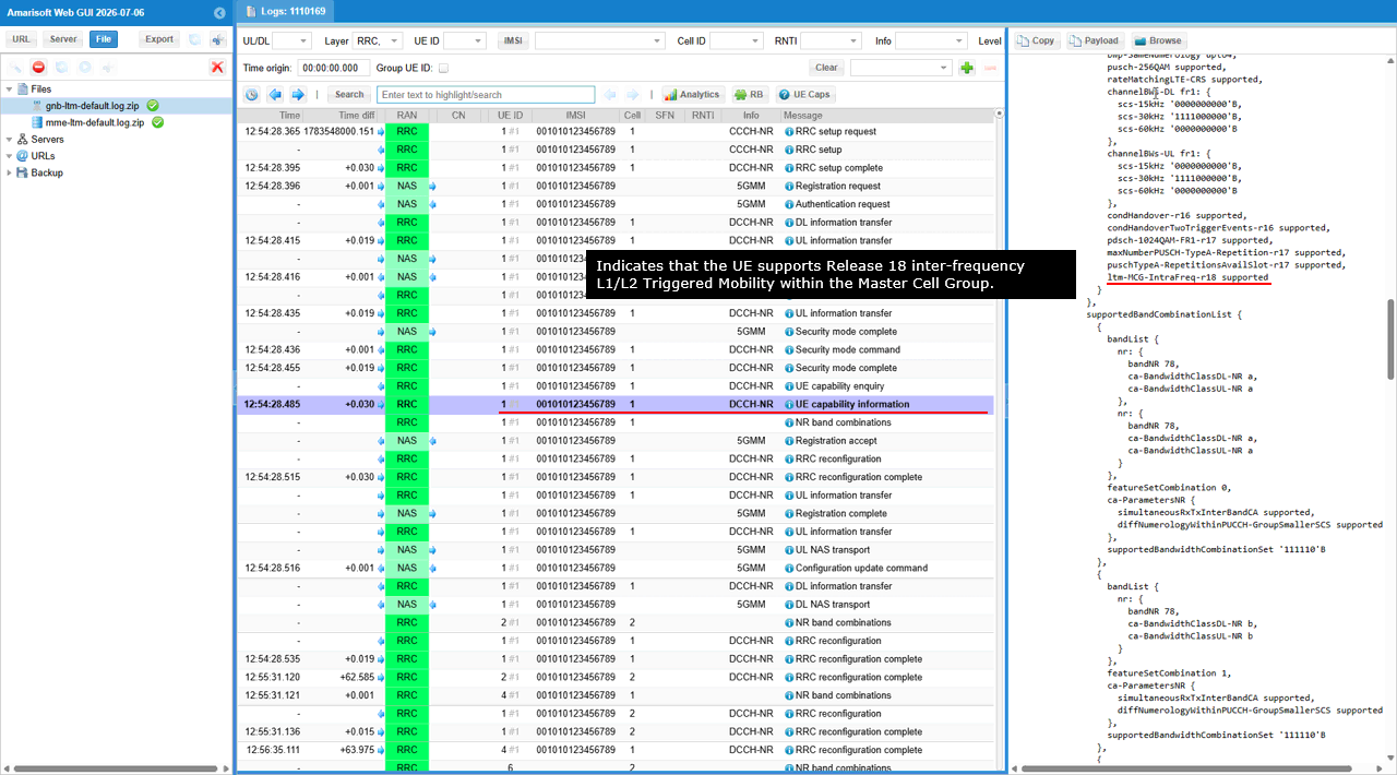
The UE capability information message reports the UE radio capabilities for NR. In the featureSetDownlinkPerCC-r18 block, the parameter ltm-MCG-IntraFreq-r18 is set to supported, indicating that the UE supports Release 18 intra-frequency L1/L2 Triggered Mobility within the Master Cell Group. This capability allows the gNB to configure and trigger LTM between NR cells operating on the same frequency layer.
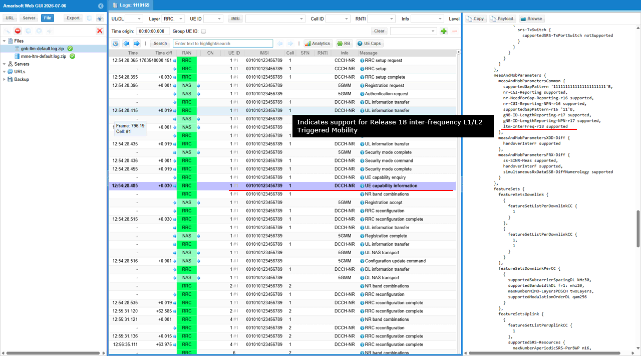
The measAndMobParametersCommon block reports the UE measurement and mobility capabilities. The parameter ltm-InterFreq-r18 is set to supported, indicating that the UE supports Release 18 inter-frequency L1/L2 Triggered Mobility between NR cells operating on different frequencies.
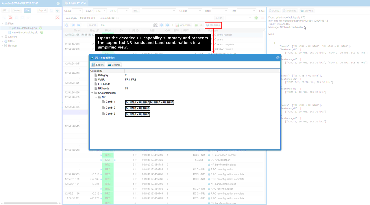
The UE Caps window provides a simplified summary of the decoded UE capability information. Selecting UE Caps opens the capability view, where the NR bands section confirms support for band n78 and the CA combination section lists the supported downlink and uplink band combinations.
In this example, Comb. 1 shows a two-carrier NR combination using DL n78A + UL n78A together with another DL n78A + UL n78A component. Comb. 2 shows DL n78B + UL n78B, while Comb. 3 shows DL n78A + UL n78A. These entries confirm the UE bandwidth-class and carrier-combination capabilities reported for band n78.
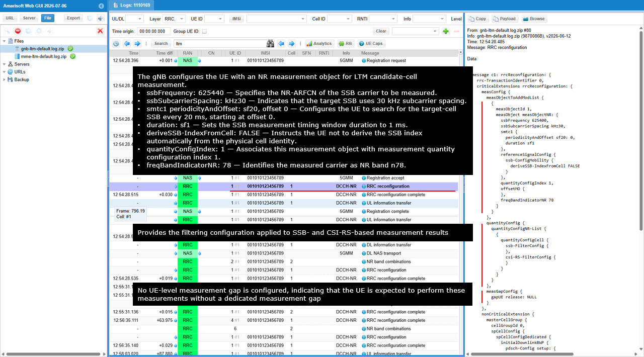
The measConfig block in the RRC reconfiguration message configures the NR measurement object used for LTM candidate-cell measurement. Inside measObjectToAddModList, measObjectId is set to 1 and measObjectNR defines the target NR carrier. The parameter ssbFrequency is set to 625400, ssbSubcarrierSpacing is set to kHz30, and freqBandIndicatorNR is set to 78, identifying the candidate carrier as band n78 with 30 kHz SSB subcarrier spacing.
Inside smtc1, periodicityAndOffset is set to sf20 with offset 0, so the UE searches for the candidate-cell SSB every 20 ms starting from offset 0. The parameter duration is set to sf1, defining a 1 ms SSB measurement window.
Inside referenceSignalConfig, the ssb-ConfigMobility block sets deriveSSB-IndexFromCell to FALSE. This means that the UE does not derive the SSB index automatically from the physical cell identity and instead uses the configured SSB measurement information.
The parameter quantityConfigIndex is set to 1, linking this measurement object to the first entry in the quantityConfig block. Inside quantityConfigNR-List, the quantityConfigCell block provides the filtering configuration for SSB-based and CSI-RS-based measurement results through ssb-FilterConfig and csi-RS-FilterConfig.
The measGapConfig block contains gapUE release NULL, indicating that no dedicated UE measurement gap is configured. The UE is therefore expected to perform the configured candidate-cell measurements without using a separate measurement gap.
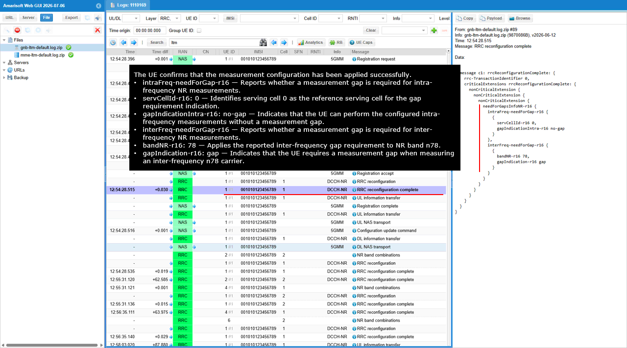
The RRC reconfiguration complete message confirms that the UE successfully applied the measurement configuration and reports its measurement-gap requirements.
Inside needForGapsInfoNR-r16, the intraFreq-needForGap-r16 block sets servCellId-r16 to 0 and gapIndicationIntra-r16 to no-gap. This indicates that the UE can perform the configured intra-frequency NR measurements using serving cell 0 as the reference without a dedicated measurement gap.
The interFreq-needForGap-r16 block sets bandNR-r16 to 78 and gapIndication-r16 to gap. This indicates that the UE requires a measurement gap when performing inter-frequency measurements on NR band n78.
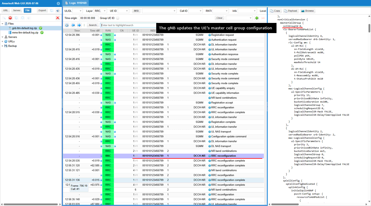
The masterCellGroup block in the RRC reconfiguration message updates the UE radio configuration for the serving Master Cell Group. In the rlc-BearerToAddModList block, the gNB configures the signalling radio bearers, including logicalChannelIdentity 4 mapped to servedRadioBearer srb-Identity 1 and logicalChannelIdentity 2 mapped to servedRadioBearer srb-Identity 2.
The rlc-Config block defines the AM RLC parameters for each bearer. The ul-AM-RLC and dl-AM-RLC blocks configure values such as sn-FieldLength, t-PollRetransmit, pollPDU, pollByte, maxRetxThreshold, t-Reassembly, and t-StatusProhibit.
The mac-LogicalChannelConfig block configures uplink logical-channel parameters such as priority, prioritisedBitRate, bucketSizeDuration, logicalChannelGroup, schedulingRequestID, logicalChannelSR-Mask, and logicalChannelSR-DelayTimerApplied.
The spCellConfig block contains the serving-cell-specific configuration, including uplinkConfig and initialUplinkBWP. This RRC reconfiguration prepares the UE with the updated bearer, MAC, RLC, and serving-cell settings required before the LTM candidate-cell configuration and subsequent mobility operation.
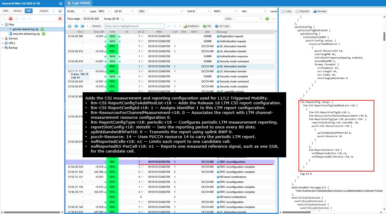
The csi-MeasConfig block adds the CSI measurement and reporting configuration used for L1/L2 Triggered Mobility. Inside ltm-CSI-ReportConfigToAddModList-r18, ltm-CSI-ReportConfigId-r18 is set to 1 to identify this LTM CSI report configuration, while ltm-ResourcesForChannelMeasurement-r18 is set to 0 to associate the report with LTM channel-measurement resource configuration 0.
The ltm-ReportConfigType-r18 block configures periodic reporting. reportSlotConfig-r18 is set to slots80, meaning that the UE transmits the LTM CSI report once every 80 slots. With the configured 30 kHz subcarrier spacing, one slot is 0.5 ms, so this corresponds to a 40 ms reporting interval. uplinkBandwidthPartId is set to 0, selecting uplink BWP 0 for report transmission, and pucch-Resource is set to 14, selecting PUCCH resource 14 to carry the report.
The ltm-ReportContent-r18 block limits the report content. nofReportedCells-r18 is set to n1, so the UE reports one candidate cell, while nofReportedRS-PerCell-r18 is set to n1, so one measured reference signal, such as one SSB, is reported for that candidate cell.
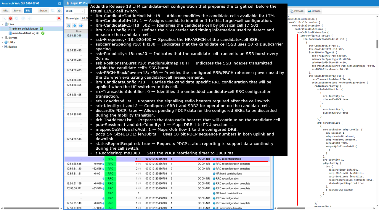
The ltm-CandidateToAddModList-r18 block adds the Release 18 LTM candidate-cell configuration that prepares the target cell before the actual L1/L2 cell switch. The parameter ltm-CandidateId-r18 is set to 1 to identify this candidate configuration, while ltm-CandidatePCI-r18 is set to 502 to identify the target cell by its physical cell ID.
Inside ltm-SSB-Config-r18, ssb-Frequency-r18 is set to 626400, subcarrierSpacing-r18 is set to kHz30, and ssb-Periodicity-r18 is set to ms20. These parameters define the candidate-cell SSB carrier, subcarrier spacing, and SSB burst periodicity used by the UE for detection and measurement. The parameter ssb-PositionsInBurst-r18 is set to mediumBitmap f0H to indicate the configured SSB positions within the candidate-cell SSB burst. The parameter ssb-PBCH-BlockPower-r18 is set to -56 dBm and provides the reference SSB/PBCH transmission power used when evaluating candidate-cell measurements.
The ltm-CandidateConfig-r18 block contains the candidate-specific RRC configuration that will be applied when the UE switches to this cell. The rrc-TransactionIdentifier is set to 0 to identify the embedded RRC configuration transaction.
Inside radioBearerConfig, srb-ToAddModList prepares SRB1 and SRB2 for operation on the candidate cell. The parameter discardOnPDCP is set to true for both signalling radio bearers, allowing pending PDCP data associated with these SRBs to be discarded during the mobility transition.
The drb-ToAddModList block prepares the data radio bearer that will continue on the candidate cell. The parameters pdu-Session and drb-Identity are both set to 1, mapping DRB1 to PDU session 1. The mappedQoS-FlowsToAdd value of 1 associates QoS flow 1 with this DRB.
Inside pdcp-Config, pdcp-SN-SizeUL and pdcp-SN-SizeDL are set to len18bits, so 18-bit PDCP sequence numbers are used in both uplink and downlink. The parameter statusReportRequired is set to true to support PDCP status reporting and data continuity during the cell switch. The parameter t-Reordering is set to ms3000, configuring the PDCP reordering timer to 3000 ms.
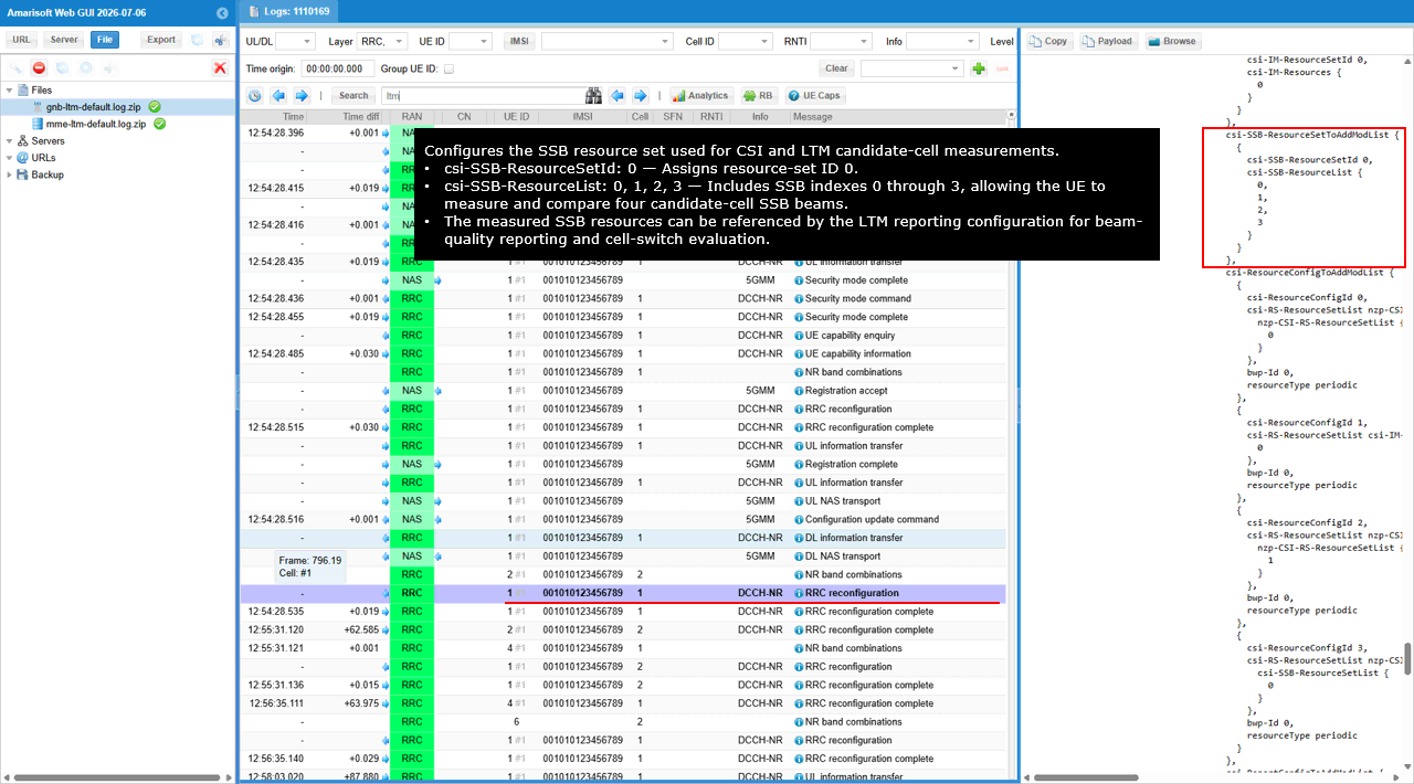
The csi-SSB-ResourceSetToAddModList block configures the SSB resource set used for CSI and LTM candidate-cell measurements. The parameter csi-SSB-ResourceSetId is set to 0 to identify this resource set.
Inside csi-SSB-ResourceList, SSB indexes 0, 1, 2, and 3 are included. This allows the UE to measure and compare the four configured SSB beams of the candidate cell. The measured SSB resources can then be referenced by the LTM CSI reporting configuration for beam-quality reporting and candidate-cell switch evaluation.
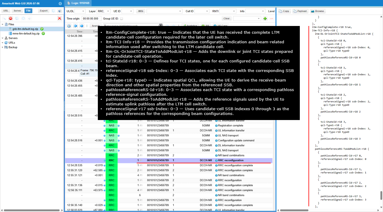
The ltm-ConfigComplete-r18 parameter is set to true, indicating that the UE has received the complete candidate-cell configuration required for the later LTM cell switch.
The ltm-TCI-Info-r18 block provides the transmission configuration indication and beam-related information prepared for the candidate cell. Inside ltm-DL-OrJointTCI-StateToAddModList-r18, tci-StateId-r18 values 0 through 3 define four candidate-cell TCI states.
For each TCI state, referenceSignal-r18 identifies one candidate-cell SSB index from 0 through 3. The qcl-Type-r18 parameter is set to typeD, indicating spatial QCL. This allows the UE to derive the receive beam direction and related spatial properties from the corresponding candidate-cell SSB.
The pathlossReferenceRS-Id-r18 parameter associates each TCI state with a pathloss reference signal configuration. Inside pathlossReferenceRS-ToAddModList-r18, pathlossReferenceRS-Id-r17 values 0 through 3 are mapped to referenceSignal-r17 SSB indexes 0 through 3. These SSBs are used as pathloss references when the UE determines the uplink transmission parameters after switching to the candidate cell.
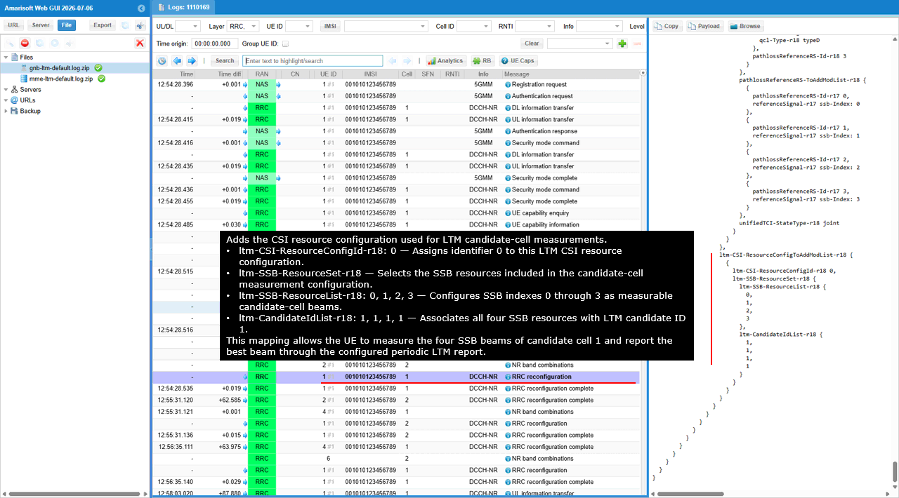
The ltm-CSI-ResourceConfigToAddModList-r18 block adds the CSI resource configuration used for LTM candidate-cell measurement. The parameter ltm-CSI-ResourceConfigId-r18 is set to 0 to identify this LTM CSI resource configuration.
Inside ltm-SSB-ResourceSet-r18, the ltm-SSB-ResourceList-r18 includes SSB indexes 0, 1, 2, and 3. This allows the UE to measure all four configured SSB beams of the candidate cell.
The ltm-CandidateIdList-r18 contains candidate ID 1 for each SSB resource. This maps all four SSB indexes to LTM candidate 1, allowing the UE to measure the candidate-cell beams and report the best beam through the configured periodic LTM CSI report.
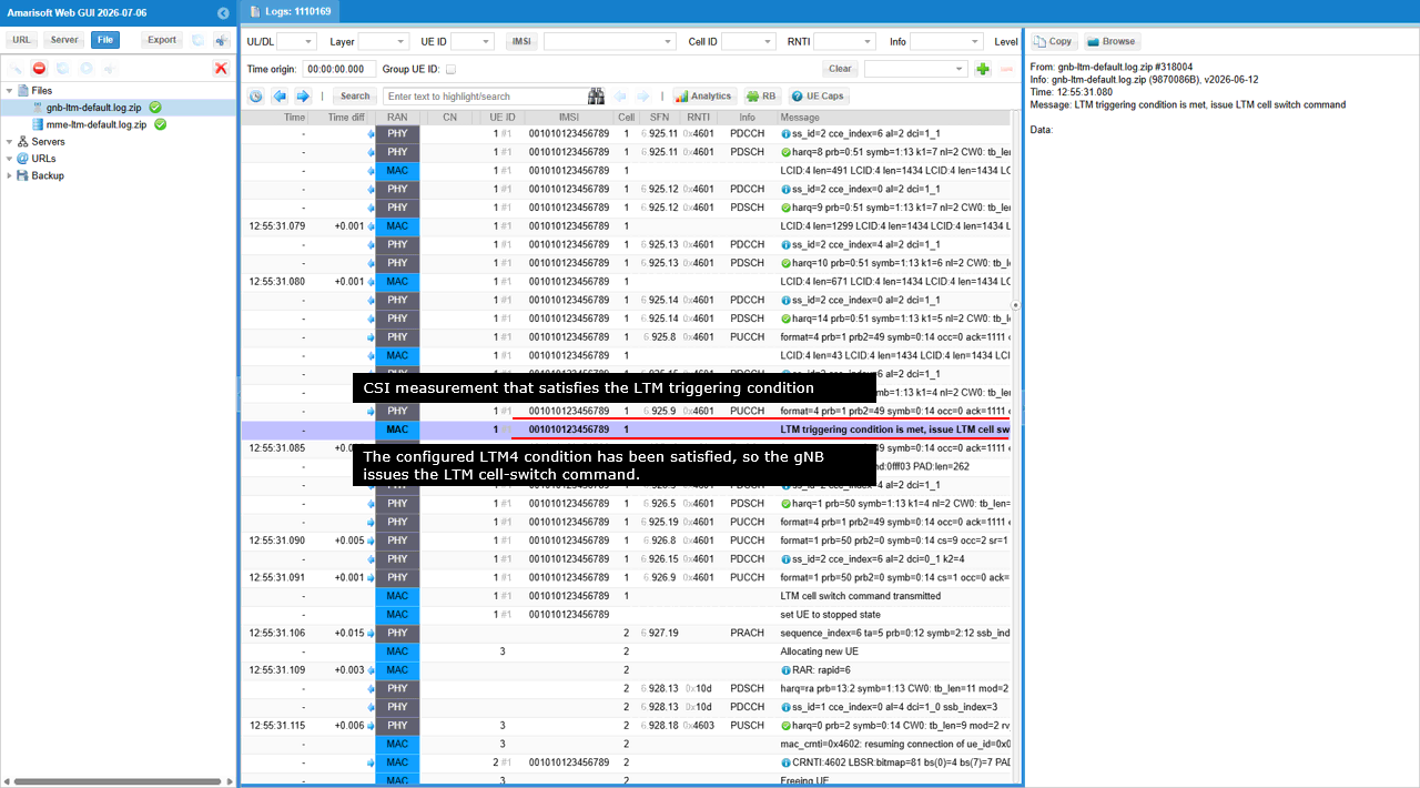
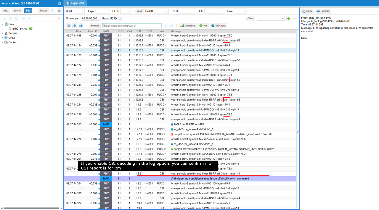
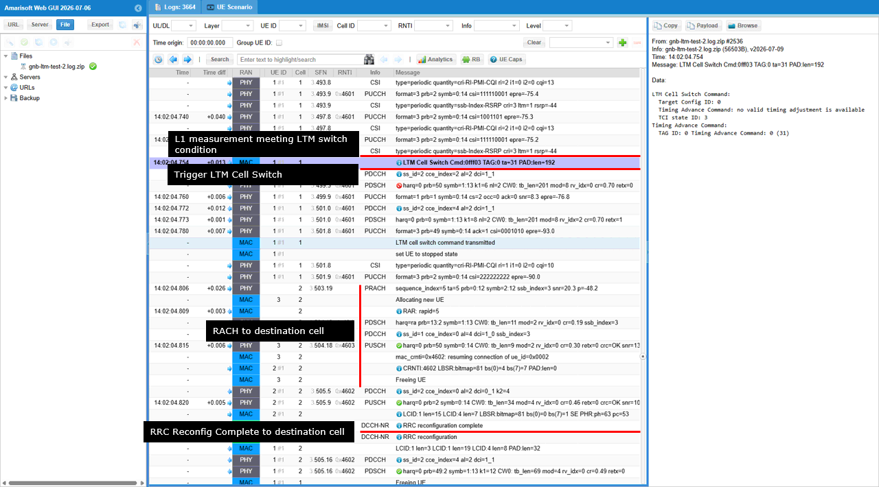
The MAC and PHY logs show the LTM execution after the UE reports the candidate-cell CSI measurement. The log entry LTM triggering condition is met indicates that the configured LTM4 threshold and count condition have been satisfied based on the received CSI report.
The gNB then issues the LTM cell-switch command through lower-layer signaling. The following log entry LTM cell switch command transmitted confirms that the command has been sent to the UE, after which the UE is placed in a stopped state on the source cell.
The UE then accesses the prepared target cell using PRACH. The target cell detects the random access preamble, allocates a new UE context, and assigns a new C-RNTI. The subsequent PDSCH, PUSCH, and MAC control-element exchanges confirm that the UE has completed access to the target cell and resumed communication after the L1/L2 triggered cell switch.
In this example, the reported RSRP for the LTM candidate improves from approximately -58 dBm to -44 dBm. After the configured threshold and count requirements are satisfied, the MAC log displays LTM triggering condition is met, issue LTM cell switch command. This confirms that the decoded CSI report was used to evaluate the LTM4 condition and trigger the lower-layer cell-switch command.
The LTM Cell Switch Cmd MAC control element instructs the UE to switch to the prepared target configuration. Target Config ID is set to 0, identifying the candidate configuration that the UE must apply. TCI state ID is set to 3, selecting the prepared beam associated with TCI state 3 for the target-cell access.
Timing Advance Command indicates that no valid timing adjustment is available. Therefore, the UE cannot reuse a preconfigured timing-advance value for the target cell and must establish uplink timing through the subsequent random access procedure.

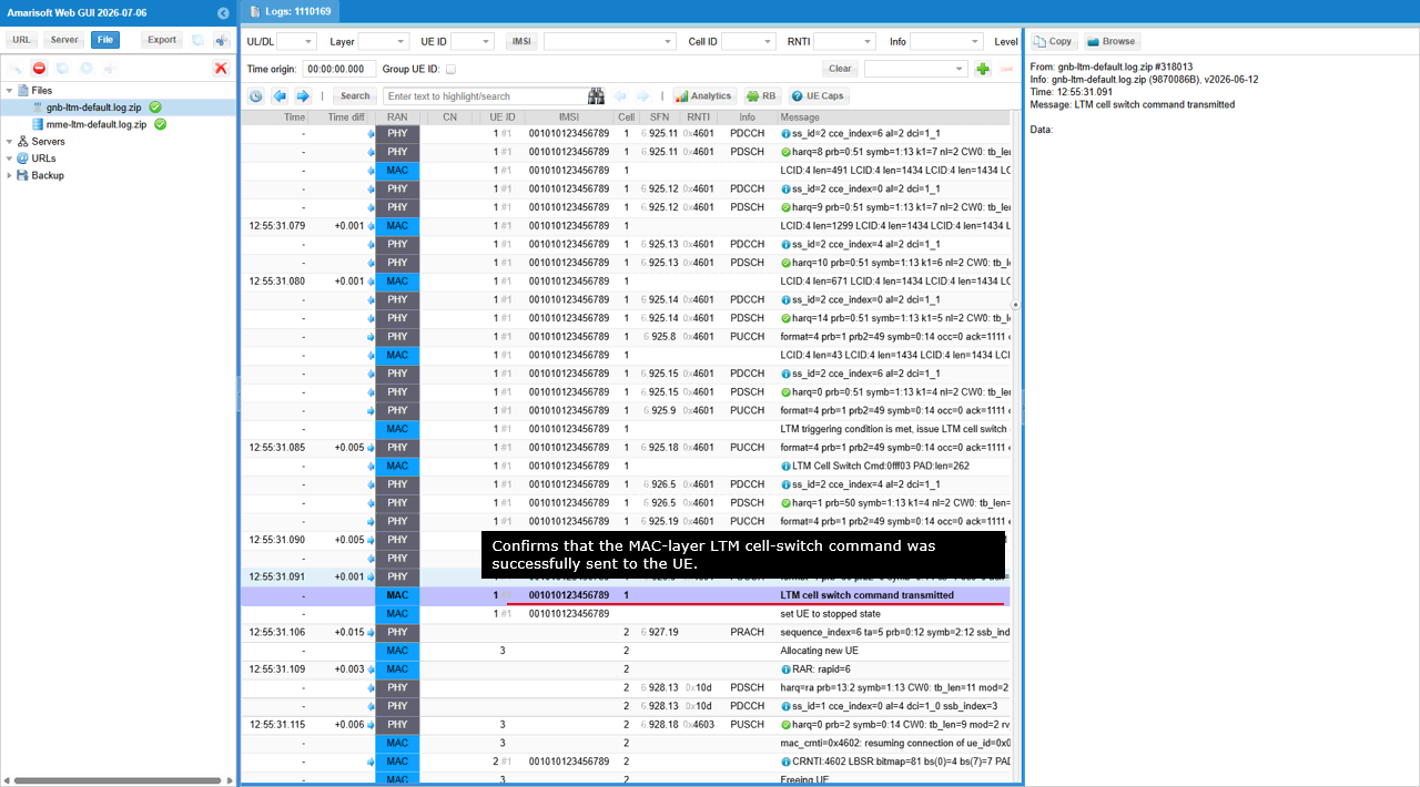
The LTM cell switch command transmitted log confirms that the MAC-layer LTM cell-switch command was successfully delivered to the UE. After this confirmation, the source-cell UE context is moved to the stopped state and the UE begins random access on the prepared target cell.
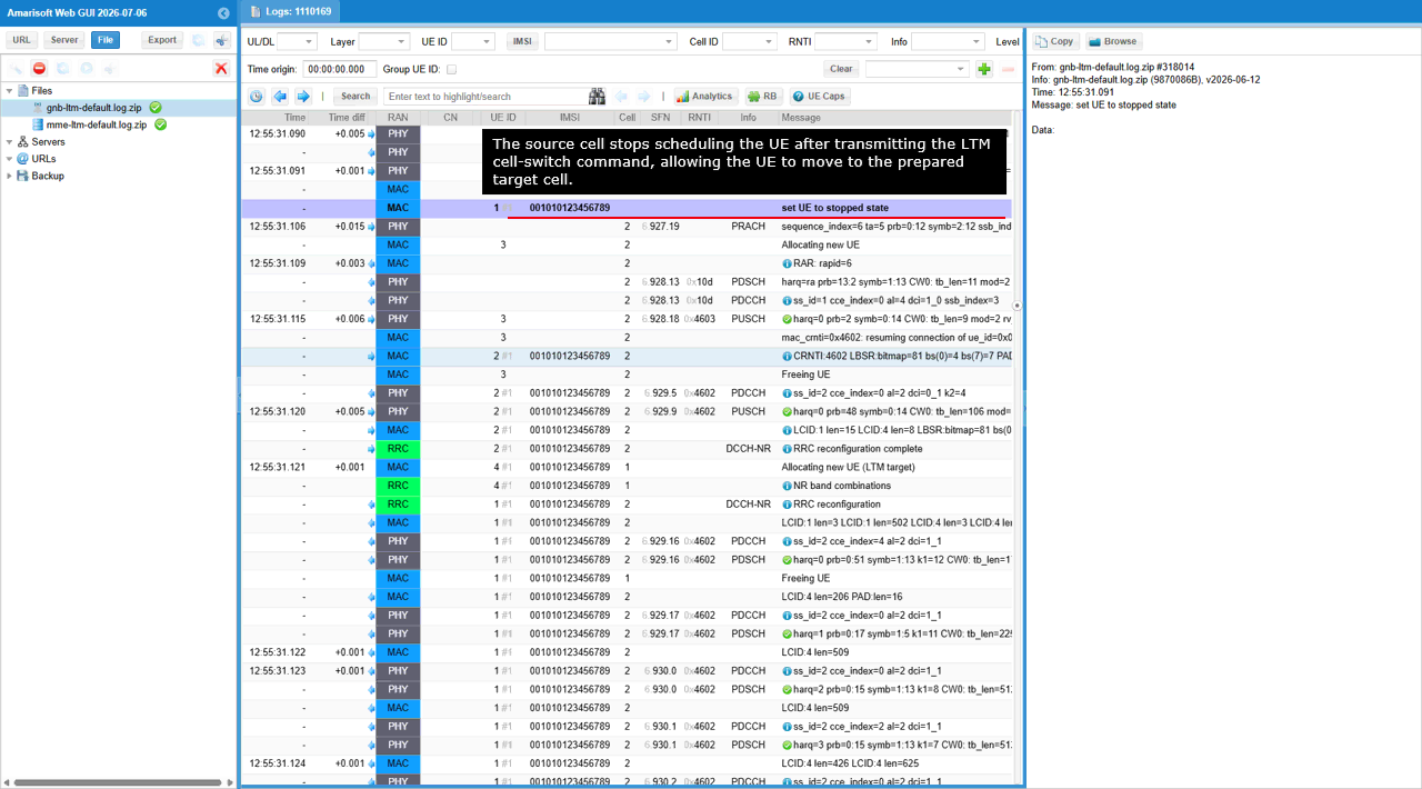
The set UE to stopped state log indicates that the source cell stops scheduling the UE after transmitting the LTM cell-switch command. This prevents further user-plane and control-plane transmission on the old serving cell while the UE moves to the prepared target cell.
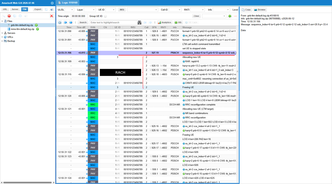
The following PRACH log on cell 2 shows that the UE begins random access toward the target cell. The target cell detects the preamble, allocates a temporary UE context, sends the Random Access Response, and assigns a new C-RNTI. Subsequent PUSCH, PDSCH, MAC, and RRC activity confirms that the UE resumes communication on the target cell and completes the LTM transition.
The PRACH log shows that the UE starts random access on target cell 2 immediately after leaving the source cell. The detected preamble uses sequence_index 6 and was received with ssb_index 3, which matches the TCI state selected in the LTM cell-switch command. The UE therefore accesses the prepared target cell through the selected candidate-cell beam before receiving the Random Access Response and completing the remaining RACH procedure.
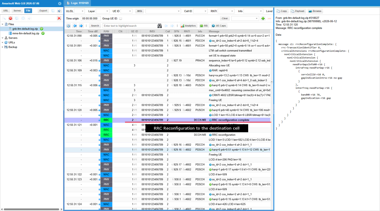
The RRC reconfiguration complete message confirms that the UE has successfully applied the prepared target-cell RRC configuration after accessing cell 2. The message is transmitted on DCCH-NR through the target cell, confirming that the LTM cell switch and subsequent RRC configuration activation have completed successfully.
The needForGapsInfoNR-r16 block again reports the UE measurement-gap capability. Inside intraFreq-needForGap-r16, servCellId-r16 is set to 0 and gapIndicationIntra-r16 is set to no-gap, indicating that intra-frequency measurements can be performed without a dedicated gap. Inside interFreq-needForGap-r16, bandNR-r16 is set to 78 and gapIndication-r16 is set to gap, indicating that inter-frequency measurements on band n78 require a measurement gap.
Test 2 : SA Intra Frequency - LTM4 and L3 Measurement
In this test, I will show a simple scenario for triggering L1/L2 Triggered Mobility between two NR SA cells. The mobility is triggered by directly changing the cell power, causing the UE measurement result to satisfy the configured condition. The UE sends a measurement report, and the network then triggers the UE to switch to the selected target cell using L1/L2 signaling.
Configuration
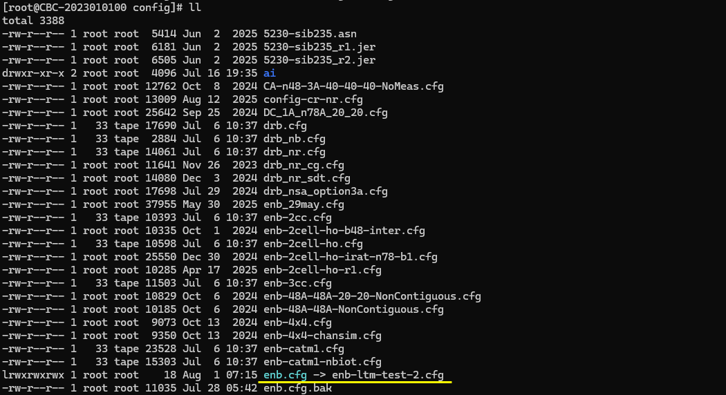
I used the enb-ltm-test-2.cfg which is copied and modified from gnb-sa.cfg
I also used mme-ims.cfg as it is.
I used the ue-nr-sa-ltm.cfg which is copied and modified from ue-nr-sa.cfg
Configure enb-ltm-test-2.cfg as below.
This configuration enables a two-cell NR SA LTM test scenario. N_CELL is set to 2 to create the serving and target cells, and N_ANTENNA_DL is set to 2 to configure 2×2 MIMO transmission. CONDITIONAL_HO is disabled because this test uses L1/L2 Triggered Mobility rather than Conditional Handover, while LTM is enabled to activate the LTM-specific configuration and procedure.
This configuration defines the LTM relationship between the two NR cells. Cell 1 is configured as the serving cell, while cell 2 is prepared in advance as an LTM candidate target. The preprocessor first assigns default values of 0 to FR2, CONDITIONAL_HO, and LTM when those variables are not explicitly defined. Because LTM is enabled for this test, the LTM-specific configuration is included instead of relying only on the conventional neighbor-cell configuration.
Within the serving-cell configuration, configuration_trigger: "immediate" instructs the gNB to prepare and configure the LTM candidate without waiting for an additional measurement event to occur first. This allows the UE to receive the candidate-cell configuration in advance, so that the later mobility execution can be triggered through L1/L2 signaling with less RRC processing at the time of the cell switch.
The report section configures periodic measurement reporting. The quantity ssb_Index_RSRP requests RSRP measurements for the individual SSB indexes detected from the candidate cell, rather than only a single cell-level measurement value. The period value of 80 configures the UE to send these reports every 80 ms. These periodic reports allow the serving gNB to continuously evaluate the radio quality of the prepared candidate cell and determine whether the configured LTM switching condition has been satisfied.
The cell_switch section defines the condition used for LTM execution. The ltm4 condition uses a threshold of -55 dBm for the configured measurement quantity. The count value of 2 requires the threshold condition to be satisfied in two measurement evaluations before the switch is triggered. This prevents a single short measurement fluctuation from immediately causing the UE to change cells. Once the condition is satisfied for the required count, the network can send the corresponding L1/L2 mobility command to move the UE to the selected candidate.
The candidate_list identifies cell_id 2 as the cell prepared for LTM from cell 1. The detailed radio and access parameters required for the UE to access cell 2 are therefore provided before the actual mobility command. On the target-cell side, ltm_target marks cell 2 as a cell that can operate as an LTM candidate. The candidate_config section selects csi_resource_type: "csi_ssb", meaning that candidate evaluation and switching are based on CSI measurement resources associated with SSB transmission.
The alternative ncell_list block is used when LTM is disabled. In that case, cell 2 is configured only as a normal neighbor cell. The conditional_handover_target parameter is included only when CONDITIONAL_HO is enabled, so it has no effect in this LTM test. Therefore, this configuration clearly separates the LTM procedure from the conventional Conditional Handover procedure while allowing the same two-cell setup to support either test through the preprocessor options.
This block configures cell 2, identified by cell_id 0x02 and physical cell ID 502, as the second NR cell in the two-cell LTM test. It operates on NR band n78 with DL-ARFCN and SSB-ARFCN set to 626400. Since this cell is configured symmetrically with cell 1, it can operate either as the current serving cell or as the prepared LTM target, depending on the UE’s present connection and the direction of mobility.
The ssb_pos_bitmap value enables four SSB positions. The ssb_precoding configuration assigns a different two-antenna precoding vector to each enabled SSB. SSB 0 is transmitted mainly through the first antenna, SSB 1 uses a balanced combination of both antennas, SSB 2 is transmitted mainly through the second antenna, and SSB 3 again uses both antennas with equal weighting. This creates different effective SSB signal levels at the UE, allowing the test to verify SSB-index-specific RSRP reporting and to evaluate how LTM reacts when the quality of a particular SSB changes. The cell_gain value of -20 dB initially reduces the overall signal level of cell 2, so its power can later be increased to satisfy the configured LTM switching condition.
The ltm block defines the LTM operation when cell 2 is the serving cell. configuration_trigger: "immediate" causes the gNB to provide the candidate-cell configuration without waiting for a separate measurement-trigger event. As a result, the UE is prepared in advance with the information required to switch from cell 2 to cell 1. This advance preparation is one of the main differences between LTM and a conventional RRC-based handover, because the final mobility execution can be initiated through lower-layer signaling without sending the full target configuration at the switching moment.
The report section requests periodic measurement reporting using ssb_Index_RSRP. This quantity reports the RSRP measured for individual SSB indexes, which is important in this test because the enabled SSBs use different precoding vectors and may therefore be received with different power levels. The period value of 80 configures the reporting interval to 80 ms. These periodic reports provide the serving gNB with frequent updates about the SSB-level radio quality of the candidate cell.
The cell_switch section defines the LTM4 execution condition. The threshold is set to -55 dBm, meaning that the relevant candidate-cell measurement must reach the configured threshold before the switching condition is considered satisfied. The count value of 2 requires the condition to be met twice before the cell switch is triggered. This provides basic filtering against a temporary measurement spike and avoids triggering mobility based on a single isolated report.
The candidate_list identifies cell_id 1 as the LTM candidate for cell 2. Therefore, when the UE is connected to cell 2, cell 1 is prepared as the possible target cell. Together with the corresponding configuration in cell 1, this creates a bidirectional LTM relationship: cell 1 can switch to cell 2, and cell 2 can switch back to cell 1.
The ltm_target section defines how cell 2 is prepared when it is used as an LTM target by the other cell. The candidate_config selects csi_resource_type: "csi_ssb", indicating that SSB-based CSI resources are used for candidate-cell evaluation and switching. This matches the ssb_Index_RSRP reporting configuration and allows the network to evaluate the candidate using measurements associated with the configured SSB resources.
When LTM is disabled, the configuration falls back to the ncell_list block. In that case, cell 1 is configured only as a normal neighboring cell. The conditional_handover_target parameter is enabled only when CONDITIONAL_HO is separately set to 1. Since Conditional Handover is disabled in this test, that parameter is not applied, and the mobility procedure is controlled exclusively by the LTM configuration.
This block(nr_cell_default) defines the common radio configuration for both NR cells. It uses 30 kHz subcarrier spacing, 20 MHz bandwidth, two downlink antennas, and one uplink antenna. For TDD operation, the default pattern uses a 5 ms period with seven downlink slots, two uplink slots, and one special slot containing six downlink symbols and one uplink symbol.
The csi_rs block configures the CSI reference-signal resources and CSI reporting. Inside resource_auto, nzp_csi_rs_period is set to 80 ms for NZP-CSI-RS transmission. When LTM is enabled, ssb_set is set to true to include an SSB-related CSI resource set for candidate-cell beam measurement. Inside csi_report_config, report_config_type is set to periodic, period is set to 80 ms, and report_quantity is set to CRI_RI_PMI_CQI. For FR2, trs_presence is set to false, so TRS is not included in the resource_auto configuration.
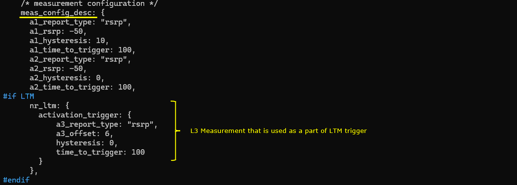
The meas_config_desc block defines the Layer 3 measurement conditions used by the mobility procedures. Within this block, nr_ltm configures the LTM-specific activation condition through activation_trigger. The a3_report_type parameter is set to rsrp, so the A3 event is evaluated using RSRP, while a3_offset is set to 6, requiring the neighboring cell to become better than the serving cell by the configured offset. The hysteresis value is 0, so no additional margin is applied, and time_to_trigger is set to 100 ms, meaning the A3 condition must remain valid for 100 ms before the LTM activation condition is satisfied.
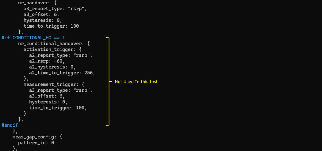
The nr_handover block defines a separate A3 condition for conventional NR handover and is not used as the LTM activation configuration. The nr_conditional_handover block defines activation_trigger and measurement_trigger conditions for conditional handover, but this block is excluded from the current test by the CONDITIONAL_HO preprocessor condition and is therefore not used.
Configure ue-nr-sa-ltm.cfg as below
N_CELL is set to 2, NR_TDD is set to 1 for TDD operation, and CELL_BANDWIDTH is set to 20 MHz. N_ANTENNA_DL is set to 2 for 2x2 downlink MIMO, while N_ANTENNA_UL is set to 1. UE_COUNT is set to 1, and CHANNEL_SIM is set to 0 because the channel simulator is not used in this test.
The cell_groups block defines one NR cell group containing the RF configurations for both cells used in the LTM test. The parameter group_type is set to nr, and multi_ue is set to 1.
Inside the cells block, the first cell uses rf_port 0, band 78, dl_nr_arfcn 625400, and ssb_nr_arfcn 625400. The second cell uses rf_port 1, band 78, dl_nr_arfcn 626400, and ssb_nr_arfcn 626400. Both cells use the bandwidth defined by CELL_BANDWIDTH, 30 kHz SSB and data subcarrier spacing, and the antenna numbers defined by N_ANTENNA_DL and N_ANTENNA_UL.
The ue_list block defines the simulated UE identity and capability settings used for the LTM test. The parameter as_release is set to 18 so that the UE advertises an NR access-stratum release that supports LTM. The parameter ue_category is set to nr, ue_count uses the value defined by UE_COUNT, and ltm_support is set to true to enable LTM capability in the simulated UE. The parameter rrc_initial_selection is set to false so that the UE does not perform automatic initial cell selection based on the strongest detected cell.
Perform the test
The cell_phy command displays the physical-layer configuration of the two NR cells used in the LTM test. Cell 0x001 uses dl_nr_arfcn 625400 and ssb_nr_arfcn 625400, while cell 0x002 uses dl_nr_arfcn 626400 and ssb_nr_arfcn 626400. Both cells operate in band n78 with 20 MHz bandwidth and 30 kHz subcarrier spacing. Since both ARFCNs belong to the same NR band, this is an intra-frequency LTM scenario.
The cell command first confirms the initial downlink power condition. Cell 0x001 with PCI 501 has dl_gain set to 0.0 dB and acts as the serving cell, while cell 0x002 with PCI 502 has dl_gain set to -20.0 dB and is initially weaker.
The cell_gain 1 -20 command reduces the dl_gain of cell 0x001 to -20 dB, and the cell_gain 2 0 command increases the dl_gain of cell 0x002 to 0 dB. This reverses the relative received power of the two cells and creates the triggering condition for LTM. The UE then detects cell 0x002 as the stronger candidate and the configured LTM measurement condition can be satisfied.
The UE trace shows the LTM cell switch from cell 0x00 with RNTI 4601 to cell 0x01 with RNTI 4602. Before the switch, the UE remains connected to the original serving cell while its RSRP decreases to approximately -58.8 dBm. After the configured LTM condition is satisfied, the UE changes to the target cell and receives the new RNTI 4602. The RSRP then improves to approximately -37.1 dBm, confirming that the UE has completed the L1/L2 triggered mobility procedure and is operating on the stronger target cell.
Log Analysis
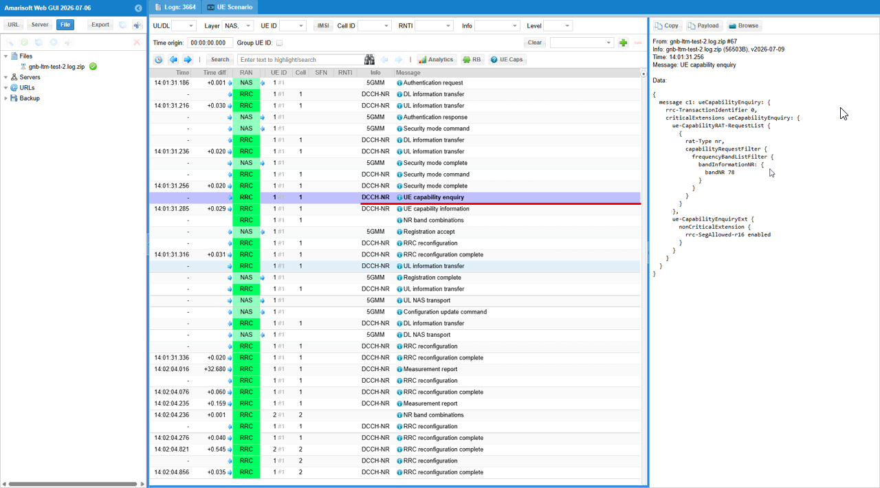
The UE Capability Enquiry message requests the UE’s NR radio capability information before the network proceeds with the LTM configuration. In ue-CapabilityRAT-RequestList, rat-Type is set to nr, and the capabilityRequestFilter limits the requested capability information to bandNR 78.
The ue-CapabilityEnquiryExt field includes nr-rrc-SegAllowed-r16 enabled, indicating that the network supports segmented NR UE capability transfer when the capability information is too large for a single message. The UE responds with the following UE Capability Information message, allowing the network to confirm that the UE supports the required NR and LTM-related functions.
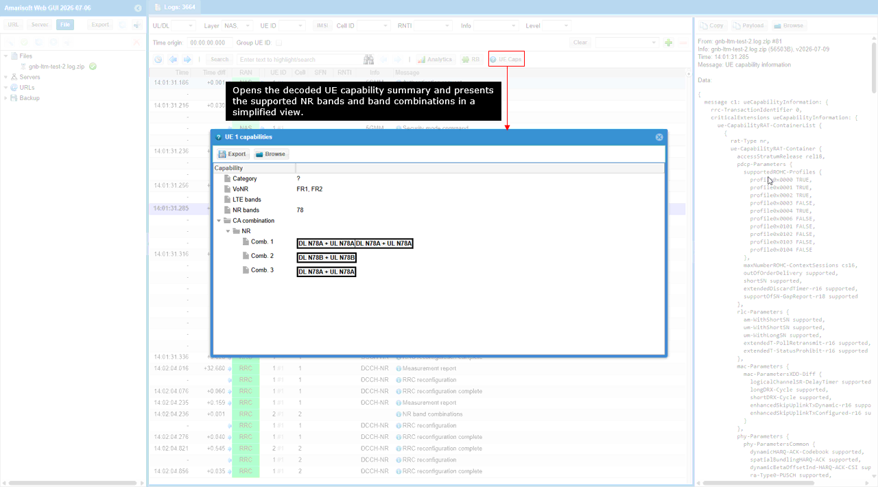
The UE Caps button opens the decoded UE capability summary, providing a simplified view of the supported NR bands and band combinations. The capability window shows that the UE supports both FR1 and FR2, with NR band 78 included in the reported band list.
Under CA combination, the UE reports three NR configurations for band n78: DL n78A + UL n78A with an additional DL n78A carrier, DL n78B + UL n78B, and DL n78A + UL n78A. These entries confirm the supported downlink and uplink bandwidth-class combinations for n78, which the network can use when selecting a compatible serving-cell and mobility configuration for the LTM test.
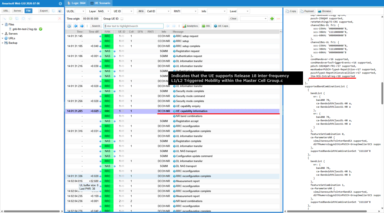
The UE Capability Information message confirms LTM support through the ltm-MG-InterFreq-r18 capability field, which is reported as supported. This indicates that the UE supports Release 18 inter-frequency Layer 1/Layer 2 Triggered Mobility within the Master Cell Group.
The supportedBandCombinationList below this capability shows the associated NR band combinations for band n78, including bandwidth classes A and B. These combinations indicate the radio configurations in which the reported LTM capability can be applied during the test.
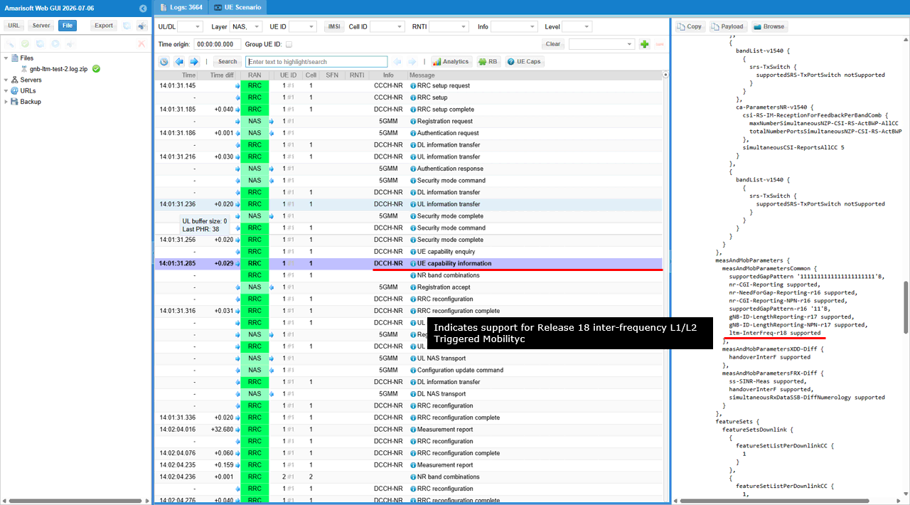
Within the measAndMobParametersCommon block, the ltm-InterFreq-r18 parameter is reported as supported. This confirms that the UE supports Release 18 inter-frequency Layer 1/Layer 2 Triggered Mobility, allowing the network to prepare and execute LTM toward a target cell operating on a different NR frequency.
Unlike the previously shown ltm-MG-InterFreq-r18 capability, which indicates support within the Master Cell Group context, ltm-InterFreq-r18 represents the UE’s general inter-frequency LTM capability.
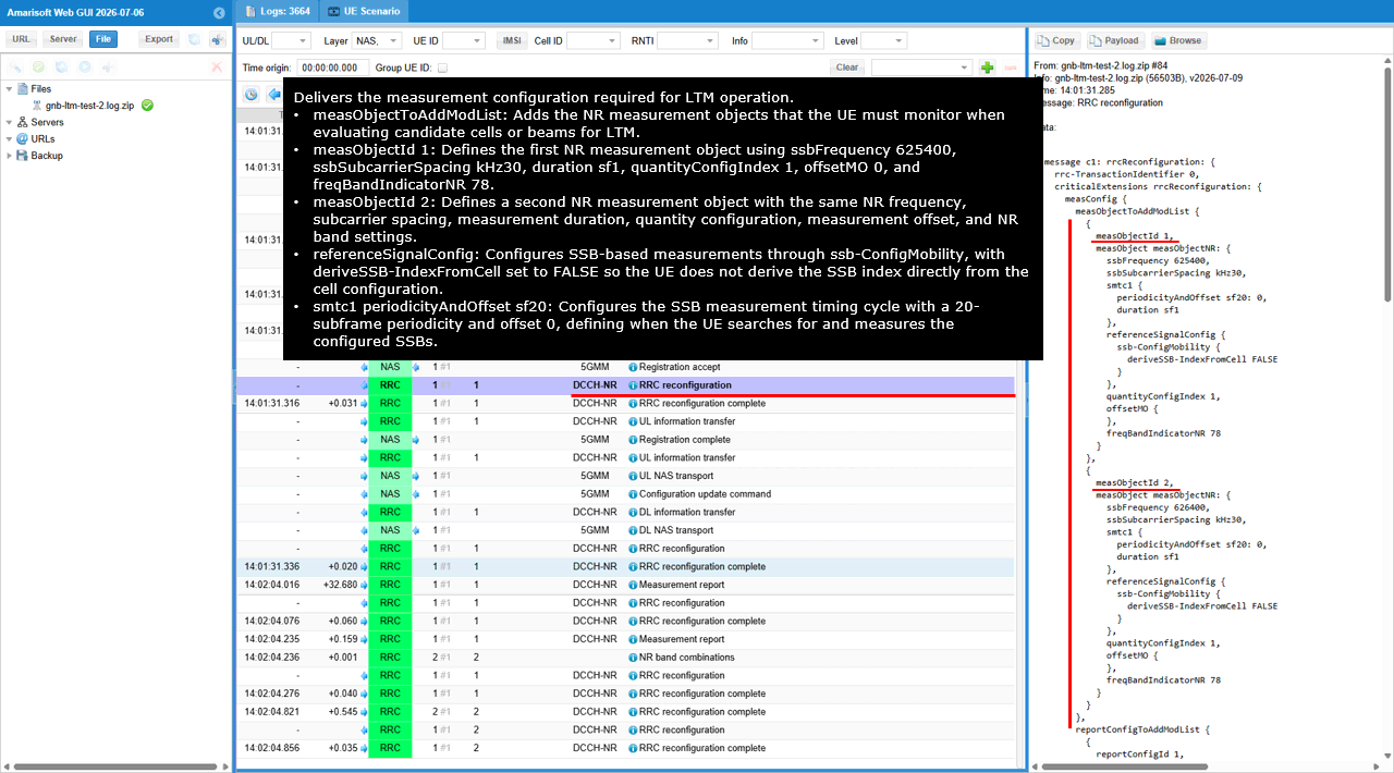
The selected RRC Reconfiguration message delivers the NR measurement configuration required for LTM operation. The measObjectToAddModList block adds measObjectId 1 and measObjectId 2, which define the NR measurement objects that the UE must monitor when evaluating serving and candidate cells or beams for LTM.
Both measurement objects use ssbFrequency 625400, ssbSubcarrierSpacing kHz30, duration sf1, quantityConfigIndex 1, offsetMO 0, and freqBandIndicatorNR 78. This configures SSB-based measurements on NR band n78 with 30 kHz subcarrier spacing. The referenceSignalConfig block selects ssb-ConfigMobility, and deriveSSB-IndexFromCell is set to FALSE, so the UE does not derive the SSB index directly from the cell configuration.
The smtc1 periodicityAndOffset parameter is set to sf20 with offset 0. As indicated by the on-screen annotation, this defines the SSB measurement timing cycle, meaning the UE searches for and measures the configured SSBs every 20 subframes starting from offset 0. The two measurement objects use the same frequency and timing configuration, but they can later be associated with different report configurations and measurement identities for separate LTM measurement purposes.
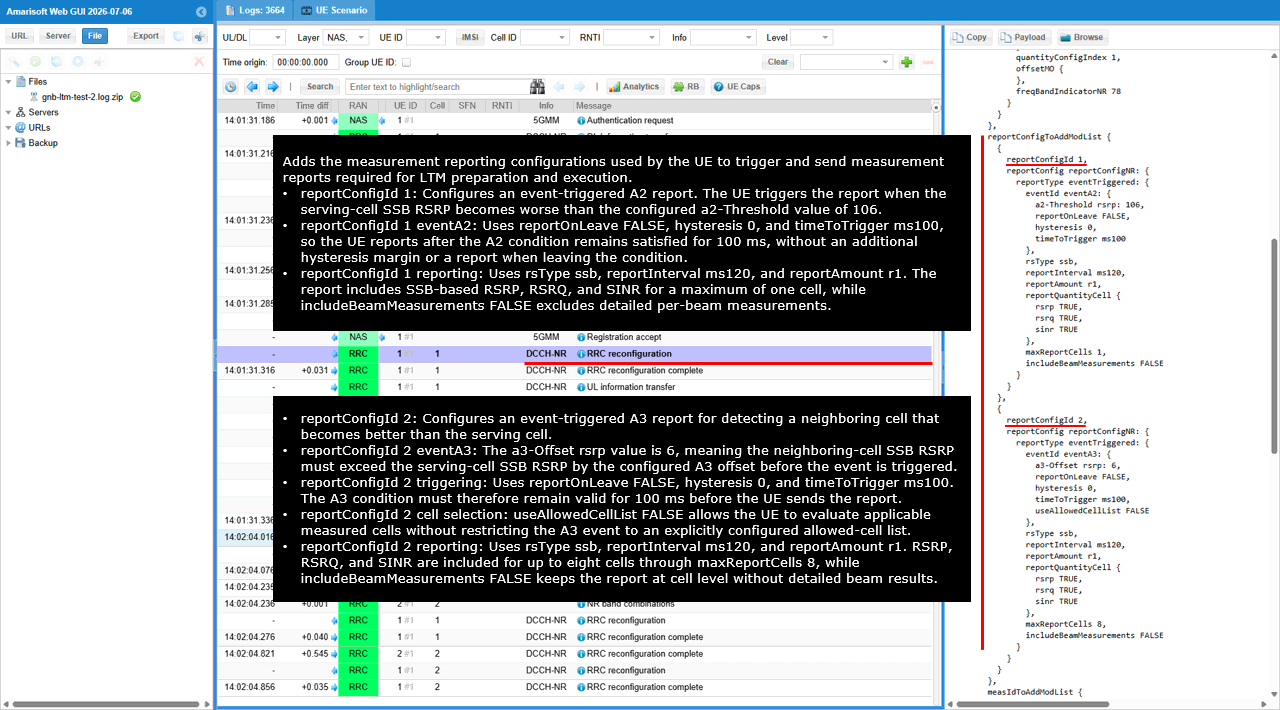
The reportConfigToAddModList block adds the measurement reporting configurations used by the UE to trigger and send Measurement Report messages required for LTM preparation and execution. reportConfigId 1 configures an event-triggered A2 report for monitoring degradation of the serving cell. The eventA2 condition uses a2-Threshold rsrp 106, so the UE triggers the report when the serving-cell SSB RSRP becomes worse than this configured threshold. reportOnLeave is set to FALSE, hysteresis is 0, and timeToTrigger is ms100, meaning the A2 condition must remain satisfied for 100 ms before reporting, with no additional hysteresis margin and no separate report when the UE leaves the A2 condition.
For reportConfigId 1, rsType is set to ssb, so the event is evaluated using SSB-based measurements. reportInterval is ms120 and reportAmount is r1, configuring a single report. The reportQuantityCell block enables RSRP, RSRQ, and SINR, while maxReportCells is 1 because this report mainly concerns the serving cell. includeBeamMeasurements is FALSE, so detailed per-beam measurement results are not included.
reportConfigId 2 configures an event-triggered A3 report for detecting a neighboring cell that becomes better than the serving cell. The eventA3 condition uses a3-Offset rsrp 6, meaning the neighboring-cell SSB RSRP must exceed the serving-cell SSB RSRP by the configured A3 offset before the event is considered satisfied. reportOnLeave is FALSE, hysteresis is 0, and timeToTrigger is ms100, so the condition must remain valid for 100 ms before the UE sends the report. useAllowedCellList is FALSE, allowing the UE to evaluate applicable measured cells without restricting the event to an explicitly configured allowed-cell list.
For reportConfigId 2, rsType is also set to ssb, reportInterval is ms120, and reportAmount is r1. The report includes cell-level RSRP, RSRQ, and SINR, and maxReportCells is set to 8 so results for up to eight candidate cells can be reported. includeBeamMeasurements is FALSE, keeping the report at cell level without detailed per-SSB beam results. As indicated by the on-screen annotations, reportConfigId 1 is used to detect serving-cell degradation, while reportConfigId 2 provides the A3 neighbor-cell measurement condition used as part of the LTM preparation and triggering process.
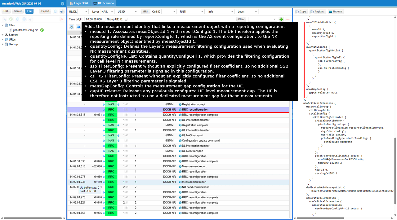
The measIdToAddModList block adds measId 1, which links measObjectId 1 with reportConfigId 1. This association instructs the UE to evaluate the NR measurement object defined by measObjectId 1 using the reporting condition configured under reportConfigId 1. In this test, reportConfigId 1 corresponds to the A2 event, so measId 1 is used to detect degradation of the serving-cell SSB RSRP and trigger the corresponding Measurement Report.
The quantityConfig block defines the Layer 3 filtering configuration applied to NR measurement quantities. Within quantityConfigNR-List, quantityConfigCell 1 contains ssb-FilterConfig and csi-RS-FilterConfig. Both fields are present without an explicitly configured filter coefficient, so no additional Layer 3 filter coefficient is signaled for either SSB-based or CSI-RS-based measurements.
The measGapConfig block controls the UE-level measurement-gap configuration. gapUE is set to release, which removes any previously configured dedicated UE measurement gap. As indicated by the on-screen annotation, the UE is therefore not instructed to use a measurement gap for these measurements at this stage of the LTM procedure.
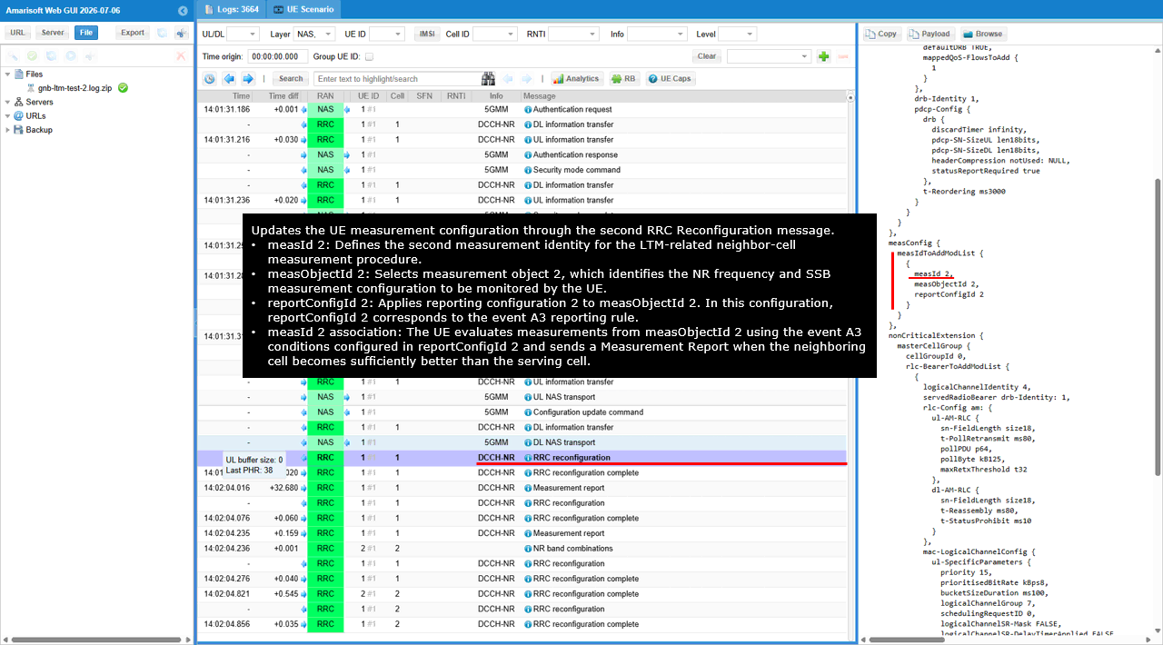
The second RRC Reconfiguration message updates the UE measurement configuration by adding measId 2 under the measIdToAddModList block. measId 2 links measObjectId 2 with reportConfigId 2, instructing the UE to evaluate the NR frequency and SSB measurement configuration defined by measObjectId 2 using the reporting condition associated with reportConfigId 2.
In this test, reportConfigId 2 contains the event A3 condition used for the LTM-related neighbor-cell measurement procedure. The UE therefore compares the measured candidate-cell SSB RSRP with the serving-cell SSB RSRP and sends a Measurement Report when the neighboring cell becomes better by the configured A3 offset and the condition remains valid for the configured time-to-trigger. As indicated by the on-screen annotation, this second measurement identity enables the UE to perform the neighbor-cell evaluation required for LTM preparation after the initial serving-cell condition has been detected.
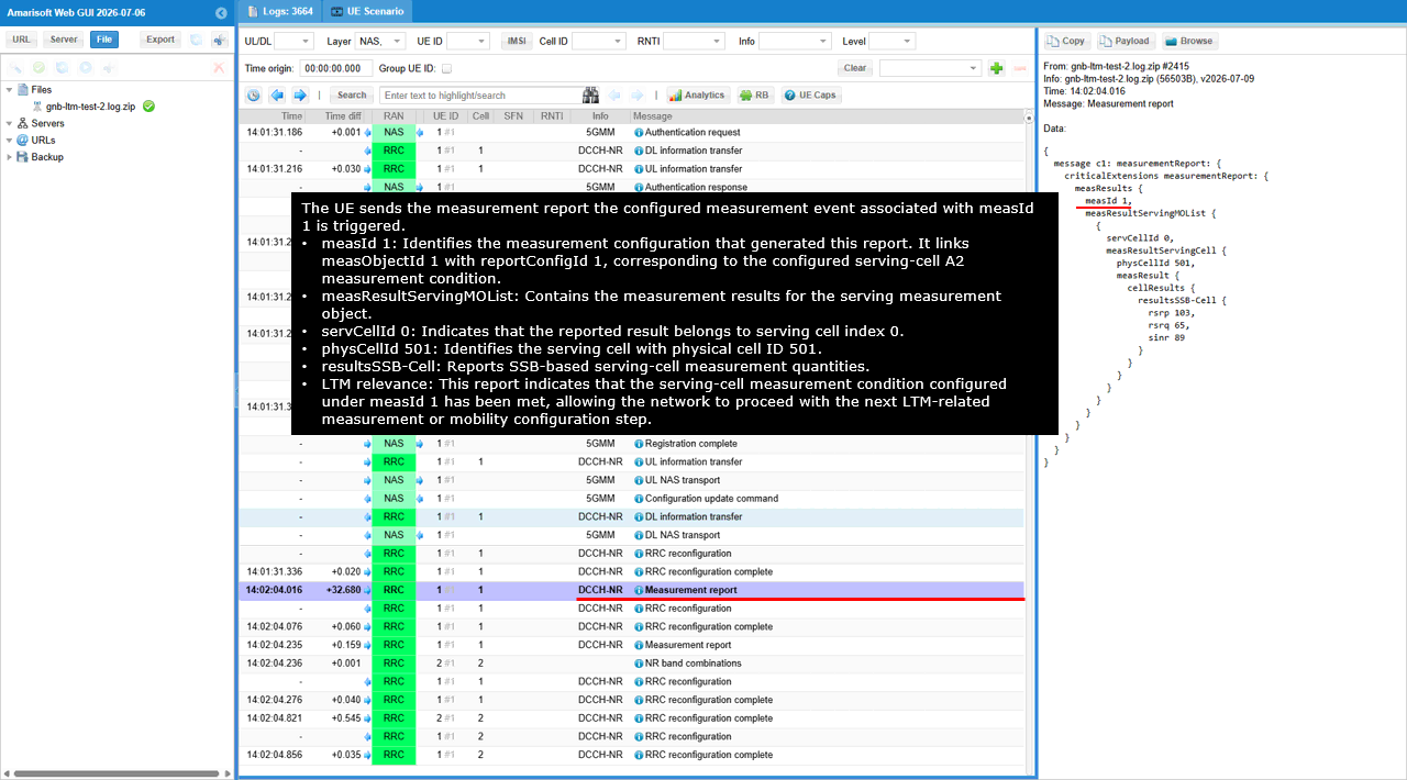
The UE sends this Measurement Report after the measurement event associated with measId 1 is triggered. measId 1 links measObjectId 1 with reportConfigId 1, which is the serving-cell A2 reporting condition configured earlier. The report therefore indicates that the serving-cell SSB RSRP has remained below the configured A2 threshold for the required time-to-trigger, allowing the network to continue with the next LTM preparation step.
The measResultServingMOList block contains the result for serving-cell index servCellId 0. Within measResultServingCell, physCellId 501 identifies the serving cell, while resultsSSB-Cell reports the SSB-based cell-level measurements. The encoded measurement values are rsrp 103, rsrq 65, and sinr 89.
As indicated by the on-screen annotation, this report confirms that the serving-cell measurement condition configured under measId 1 has been met. It acts as the initial serving-cell degradation indication, after which the network can configure or activate the neighbor-cell A3 measurement associated with measId 2 for the LTM procedure.
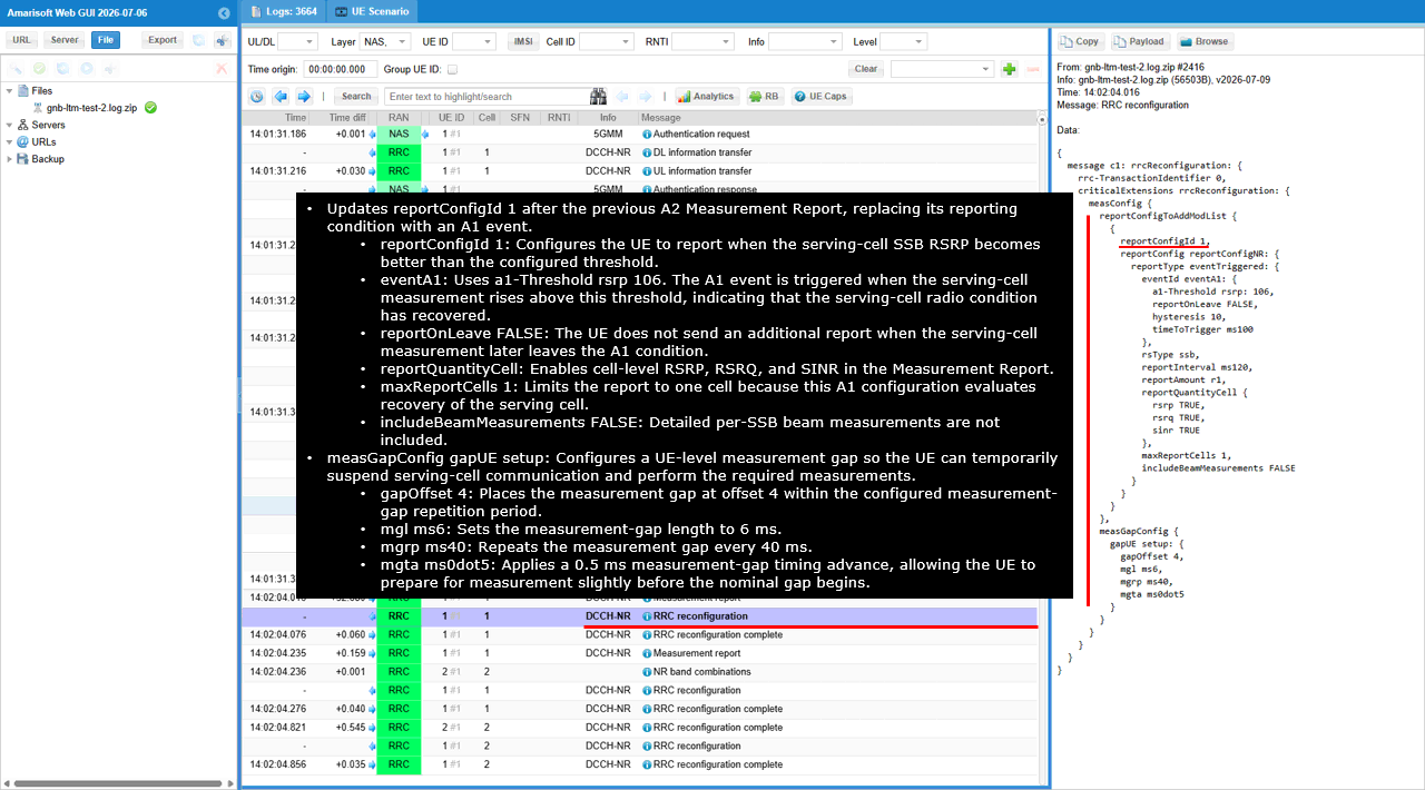
This RRC Reconfiguration updates reportConfigId 1 after the previous A2 Measurement Report, replacing the serving-cell degradation condition with an A1 recovery condition. The eventA1 configuration uses a1-Threshold rsrp 106, so the UE reports when the serving-cell SSB RSRP becomes better than this threshold. reportOnLeave is set to FALSE, hysteresis is 0, and timeToTrigger is ms100, meaning the A1 condition must remain satisfied for 100 ms before the report is sent, with no additional hysteresis margin and no separate report when the UE later leaves the condition.
The reporting parameters use rsType ssb, reportInterval ms120, and reportAmount r1. The reportQuantityCell block enables RSRP, RSRQ, and SINR, while maxReportCells 1 limits the report to the serving cell. includeBeamMeasurements is set to FALSE, so detailed per-SSB beam measurements are not included. As shown in the on-screen annotation, this configuration is used to detect that the serving-cell radio condition has recovered after the earlier A2 event.
The same RRC Reconfiguration also sets up a UE-level measurement gap through measGapConfig and gapUE setup. gapOffset is 4, mgl is ms6, mgrp is ms40, and mgta is ms0dot5. This creates a 6 ms measurement gap every 40 ms at offset 4, with a 0.5 ms timing advance, allowing the UE to temporarily suspend serving-cell communication and perform the inter-frequency measurements required for the LTM procedure.
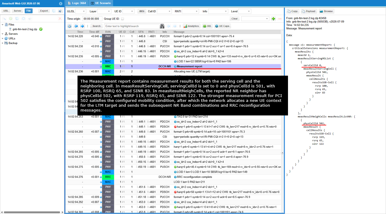
The Measurement Report contains results for both the serving cell and the neighboring candidate cell and is generated for measId 2, which is associated with the A3 neighbor-cell reporting condition used for LTM. In measResultServingMOList, servCellId 0 identifies the serving cell and physCellId 501 identifies its PCI. The serving-cell SSB measurement values are reported as rsrp 100, rsrq 65, and sinr 83.
The measResultNeighCells block reports the neighboring NR cell with physCellId 502. Its SSB measurement values are rsrp 119, rsrq 65, and sinr 122. Since the neighboring cell has a significantly stronger RSRP than the serving cell, the configured A3 condition is satisfied. As indicated by the on-screen annotation, this result allows the network to select PCI 502 as the LTM target, allocate a new UE context for that target cell, and continue with the subsequent NR Band Combinations and RRC Reconfiguration messages used to prepare the LTM execution.
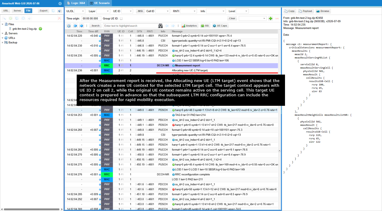
After the Measurement Report is received, the Allocating new UE (LTM target) event indicates that the network creates a new UE context for the selected LTM target cell. The target context is assigned UE ID 2 on cell 2, while the original UE context remains active as UE ID 1 on the serving cell.
This target UE context is prepared in advance so that the network can configure the target-cell resources before mobility execution. The subsequent LTM RRC Reconfiguration can therefore include the prepared target configuration and resource information needed for rapid Layer 1/Layer 2 triggered mobility, reducing the signaling and interruption required when the UE switches from the serving cell to the target cell.
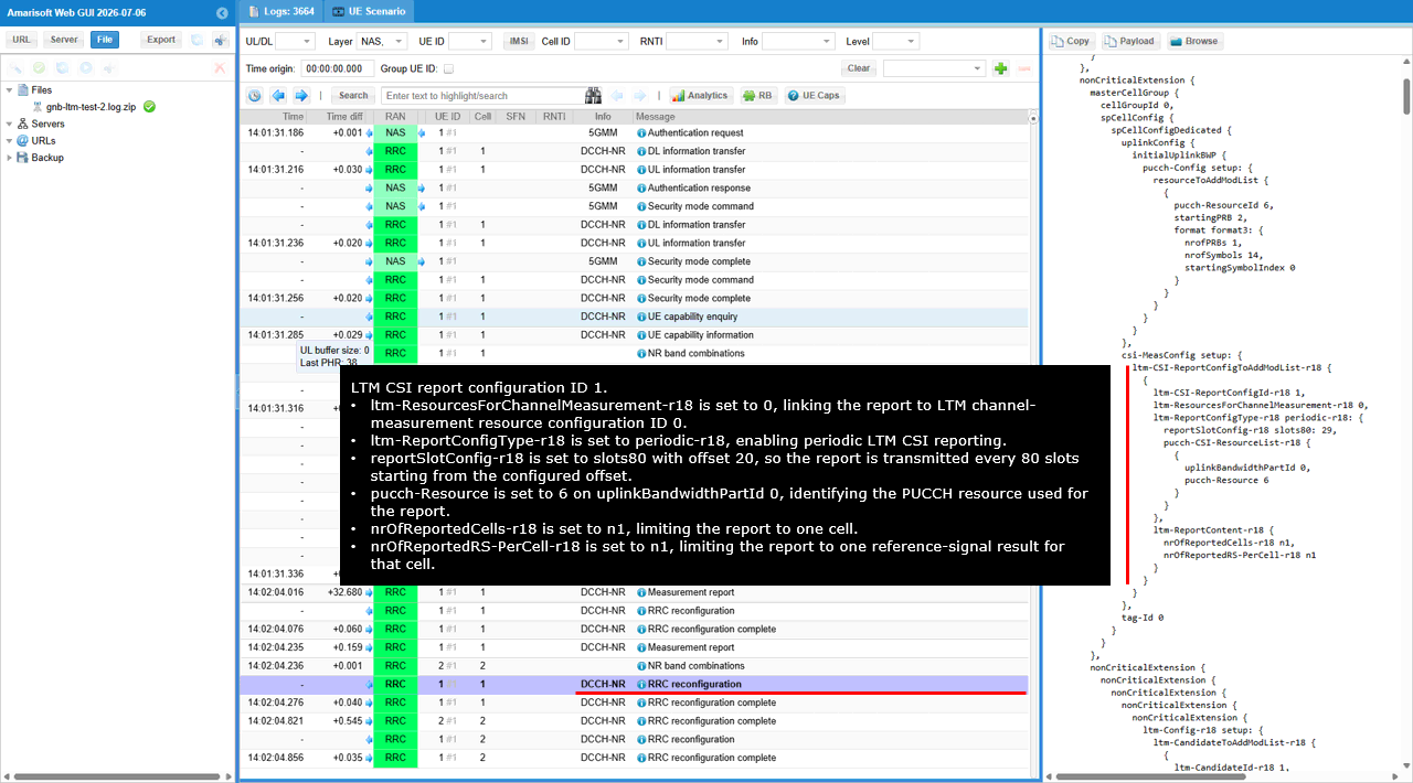
The csi-MeasConfig setup block adds ltm-CSI-ReportConfigToAddModList-r18, which configures the periodic CSI report used for LTM candidate monitoring. The ltm-CSI-ReportConfigId-r18 parameter is set to 1, identifying this LTM CSI reporting configuration, while ltm-ResourcesForChannelMeasurement-r18 is set to 0, linking the report to LTM channel-measurement resource configuration ID 0.
The ltm-ReportConfigType-r18 parameter is set to periodic-r18, so the UE sends the LTM CSI report periodically rather than only after an event. The reportSlotConfig-r18 parameter is configured as slots80 with offset 20, meaning the report is transmitted once every 80 slots starting from the configured slot offset. Within pucch-CSI-ResourceList-r18, uplinkBandwidthPartId is set to 0 and pucch-Resource is set to 6, selecting PUCCH resource 6 on uplink BWP 0 for transmission of the report.
The ltm-ReportContent-r18 block limits the reported content to one candidate cell and one reference-signal result. The nrOfReportedCells-r18 parameter is set to n1, and nrOfReportedRS-PerCell-r18 is also set to n1. As indicated by the on-screen annotation, this configuration creates LTM CSI report configuration ID 1 and provides the network with periodic channel-quality information for a single monitored LTM candidate.
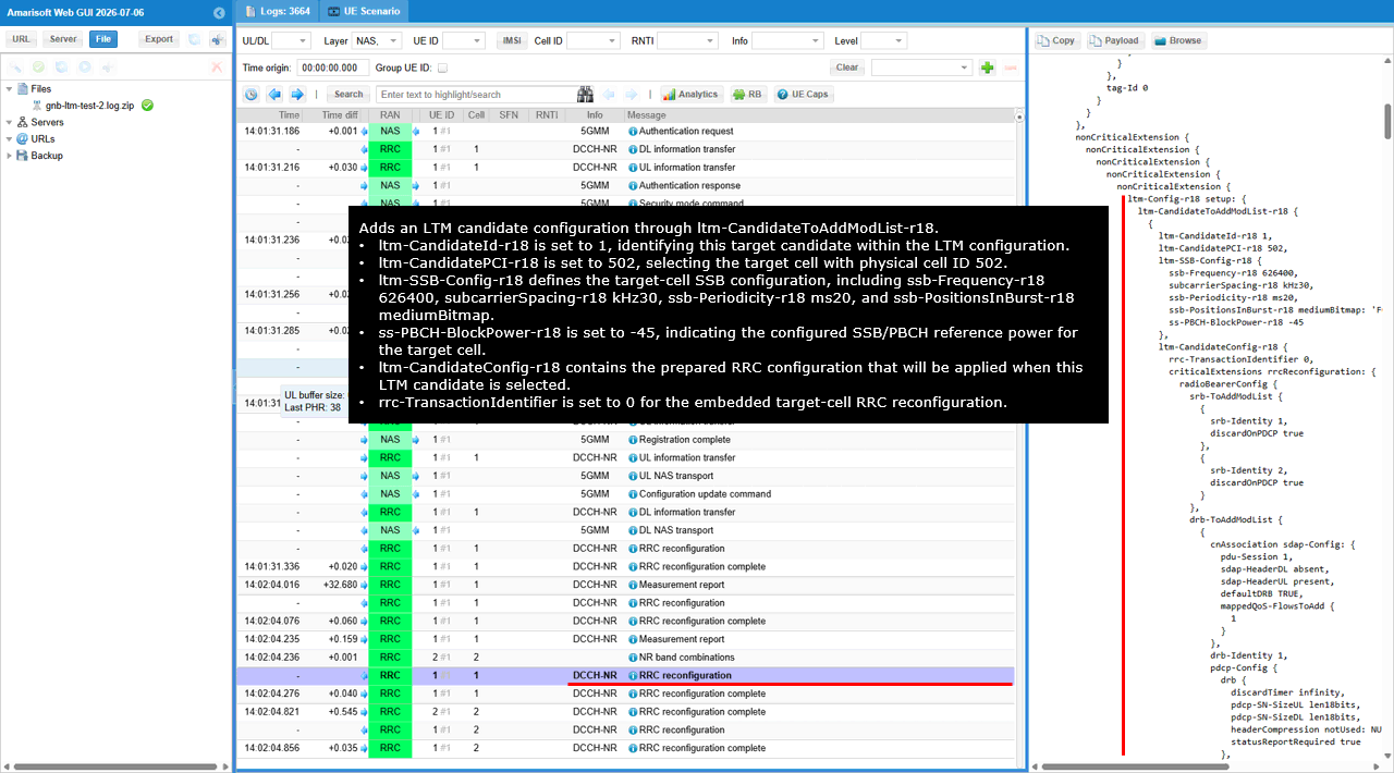
The nonCriticalExtension block adds an LTM candidate through ltm-CandidateToAddModList-r18. The ltm-CandidateId-r18 parameter is set to 1, assigning an identifier to this prepared target candidate, while ltm-CandidatePCI-r18 is set to 502, selecting the target cell with physical cell ID 502 that was identified by the previous A3 Measurement Report.
The ltm-SSB-Config-r18 block defines the target-cell SSB configuration. The ssb-Frequency-r18 parameter is set to 626400, subcarrierSpacing-r18 is kHz30, ssb-Periodicity-r18 is ms20, and ssb-PositionsInBurst-r18 uses the mediumBitmap value shown in the message. The ss-PBCH-BlockPower-r18 parameter is set to -45, indicating the configured SSB/PBCH reference power for the target cell.
The ltm-CandidateConfig-r18 block contains the prepared target-cell RRC configuration that will be applied when this LTM candidate is selected. The embedded rrc-TransactionIdentifier is set to 0, and the configuration includes target-cell radio bearer, DRB, PDCP, and related serving-cell parameters. As indicated by the on-screen annotation, this message preconfigures candidate ID 1 for PCI 502 so the UE already has the target-cell configuration before the actual LTM execution, enabling a faster switch with reduced interruption.
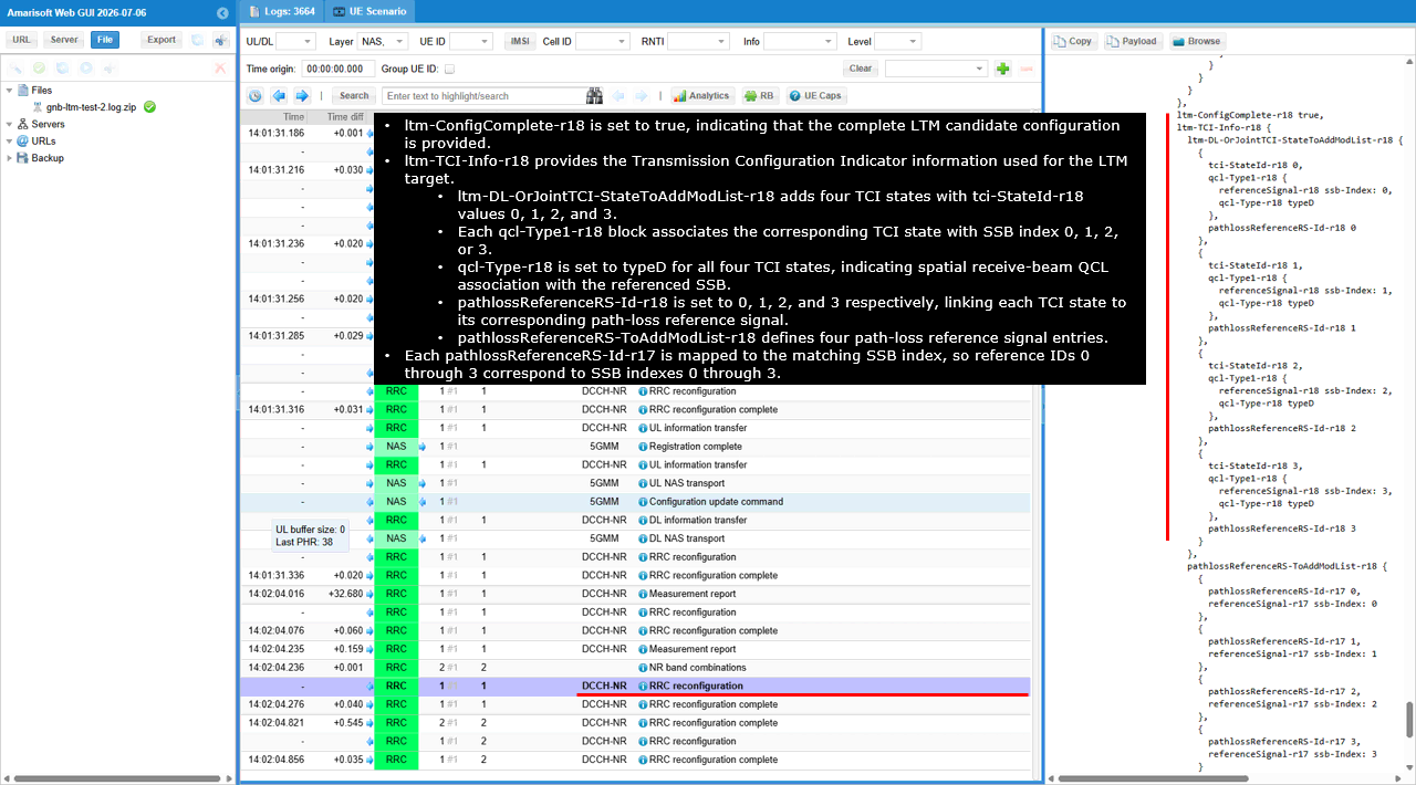
The ltm-ConfigComplete-r18 parameter is set to true, indicating that the complete configuration for the LTM candidate is included in this RRC Reconfiguration. The ltm-TCI-Info-r18 block provides the Transmission Configuration Indicator information that the UE will use to receive downlink signals from the prepared LTM target cell.
The ltm-DL-OrJointTCI-StateToAddModList-r18 block adds four TCI states with tci-StateId-r18 values 0, 1, 2, and 3. Each TCI state references the corresponding target-cell SSB index through referenceSignal-r18 ssb-Index 0, 1, 2, or 3. qcl-Type-r18 is set to typeD for all four entries, indicating that the UE can use the spatial receive-beam characteristics of the referenced SSB when receiving downlink transmissions associated with that TCI state.
Each TCI state is also linked to a path-loss reference through pathlossReferenceRS-Id-r18 values 0, 1, 2, and 3. The pathlossReferenceRS-ToAddModList-r18 block creates the corresponding path-loss reference entries and maps each reference ID to the matching target-cell SSB index. As indicated by the on-screen annotation, TCI state 0 is associated with SSB index 0 and path-loss reference ID 0, and the same one-to-one mapping is applied for indices and IDs 1 through 3. This provides the UE with prepared beam and path-loss references for multiple target-cell SSBs before LTM execution.
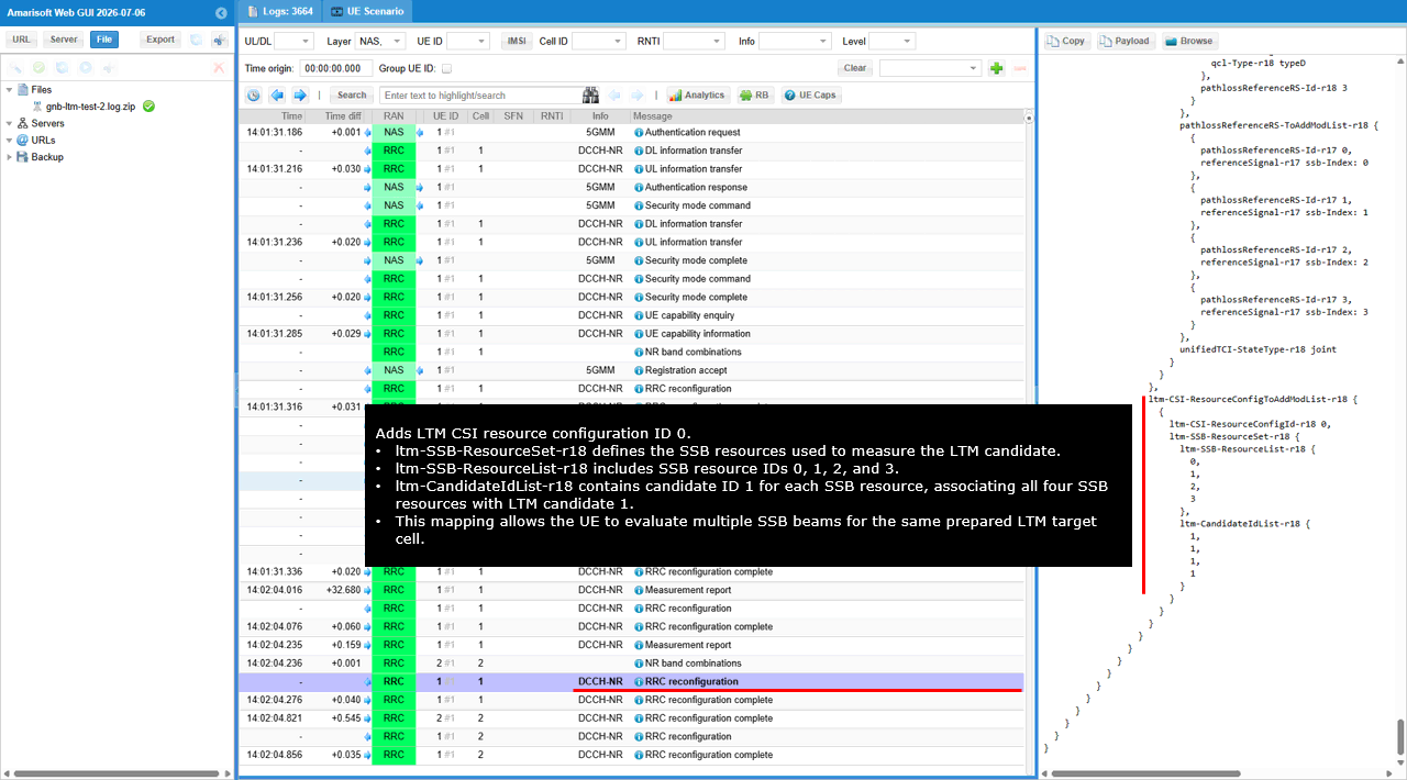
The ltm-CSI-ResourceConfigToAddModList-r18 block adds LTM CSI resource configuration ID 0. Within this configuration, ltm-SSB-ResourceSet-r18 defines the SSB resources used by the UE to measure the prepared LTM target candidate.
The ltm-SSB-ResourceList-r18 contains SSB resource IDs 0, 1, 2, and 3. The ltm-CandidateIdList-r18 contains candidate ID 1 for each corresponding resource entry, associating all four SSB resources with the same prepared LTM candidate.
As indicated by the on-screen annotation, this mapping allows the UE to measure and evaluate multiple SSB beams belonging to LTM candidate 1. The resulting measurements can then be reported through the previously configured LTM CSI report configuration, enabling the network to compare the candidate’s available beams and use the most suitable beam information during LTM execution.
The L1 measurement result satisfies the configured LTM switching condition, causing the network to trigger the LTM Cell Switch Command. The command selects Target Config ID 0 and TCI state ID 3, so the UE applies the prepared target-cell configuration and uses the beam associated with TCI state 3. The Timing Advance Command indicates that no valid timing adjustment is available, while TAG ID 0 remains associated with timing advance command value 0.
After the LTM Cell Switch Command is transmitted, the serving-cell UE context is placed in the stopped state and the UE starts accessing the destination cell. As indicated by the on-screen RACH to destination cell annotation, the UE transmits PRACH toward cell 2 using the selected target SSB, and the target cell allocates the new UE context and responds with the corresponding random-access resources.
Once random access and target-cell synchronization are completed, the UE sends RRC Reconfiguration Complete on the destination cell. As indicated by the RRC Reconfig Complete to destination cell annotation, this confirms that the prepared LTM target configuration has been successfully applied and that the UE has completed the switch from the original serving cell to the destination cell.
Test 3 : SA Intra Frequency - Early DL Sync
In this test, I will show a simple scenario for triggering L1/L2 Triggered Mobility between two NR SA cells. The mobility is triggered by directly changing the cell power, causing the UE measurement result to satisfy the configured condition. The UE sends a measurement report, and the network then triggers the UE to switch to the selected target cell using L1/L2 signaling.
Configuration
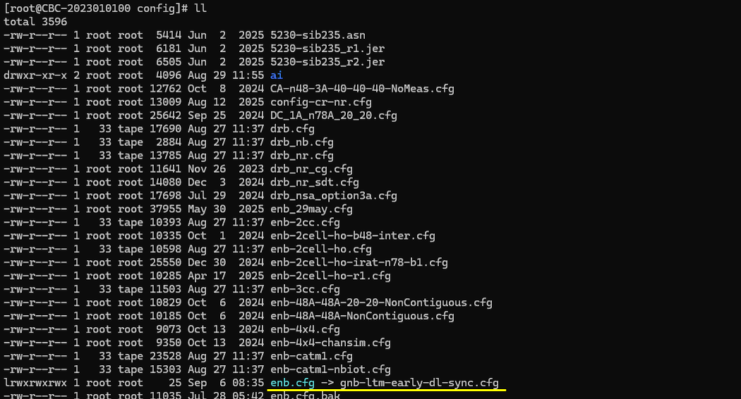
I used the gnb-ltm-early-dl-sync.cfg which is copied and modified from gnb-sa.cfg
I also used mme-ims.cfg as it is.
I used the ue-nr-sa-ltm.cfg which is copied and modified from ue-nr-sa.cfg
Configure gnb-sa-ltm.cfg as below.
This configuration enables a two-cell NR SA LTM test scenario. N_CELL is set to 2 to create the serving and target cells, and N_ANTENNA_DL is set to 2 to configure 2×2 MIMO transmission. CONDITIONAL_HO is disabled because this test uses L1/L2 Triggered Mobility rather than Conditional Handover, while LTM is enabled to activate the LTM-specific configuration and procedure.
This configuration defines the LTM relationship between the two NR cells. Cell 1 is configured as the serving cell, while cell 2 is prepared in advance as an LTM candidate target. The preprocessor first assigns default values of 0 to FR2, CONDITIONAL_HO, and LTM when those variables are not explicitly defined. Because LTM is enabled for this test, the LTM-specific configuration is included instead of relying only on the conventional neighbor-cell configuration.
Within the serving-cell configuration, configuration_trigger: "immediate" instructs the gNB to prepare and configure the LTM candidate without waiting for an additional measurement event to occur first. This allows the UE to receive the candidate-cell configuration in advance, so that the later mobility execution can be triggered through L1/L2 signaling with less RRC processing at the time of the cell switch.
The report section configures periodic measurement reporting. The quantity ssb_Index_RSRP requests RSRP measurements for the individual SSB indexes detected from the candidate cell, rather than only a single cell-level measurement value. The period value of 80 configures the UE to send these reports every 80 ms. These periodic reports allow the serving gNB to continuously evaluate the radio quality of the prepared candidate cell and determine whether the configured LTM switching condition has been satisfied.
The cell_switch section defines the condition used for LTM execution. The ltm4 condition uses a threshold of -55 dBm for the configured measurement quantity. The count value of 2 requires the threshold condition to be satisfied in two measurement evaluations before the switch is triggered. This prevents a single short measurement fluctuation from immediately causing the UE to change cells. Once the condition is satisfied for the required count, the network can send the corresponding L1/L2 mobility command to move the UE to the selected candidate.
The candidate_list identifies cell_id 2 as the cell prepared for LTM from cell 1. The detailed radio and access parameters required for the UE to access cell 2 are therefore provided before the actual mobility command. On the target-cell side, ltm_target marks cell 2 as a cell that can operate as an LTM candidate. The candidate_config section selects csi_resource_type: "csi_ssb", meaning that candidate evaluation and switching are based on CSI measurement resources associated with SSB transmission.
The alternative ncell_list block is used when LTM is disabled. In that case, cell 2 is configured only as a normal neighbor cell. The conditional_handover_target parameter is included only when CONDITIONAL_HO is enabled, so it has no effect in this LTM test. Therefore, this configuration clearly separates the LTM procedure from the conventional Conditional Handover procedure while allowing the same two-cell setup to support either test through the preprocessor options.
This block configures cell 2, identified by cell_id 0x02 and physical cell ID 502, as the second NR cell in the two-cell LTM test. It operates on NR band n78 with DL-ARFCN and SSB-ARFCN set to 626400. Since this cell is configured symmetrically with cell 1, it can operate either as the current serving cell or as the prepared LTM target, depending on the UE’s present connection and the direction of mobility.
The ssb_pos_bitmap value enables four SSB positions. The ssb_precoding configuration assigns a different two-antenna precoding vector to each enabled SSB. SSB 0 is transmitted mainly through the first antenna, SSB 1 uses a balanced combination of both antennas, SSB 2 is transmitted mainly through the second antenna, and SSB 3 again uses both antennas with equal weighting. This creates different effective SSB signal levels at the UE, allowing the test to verify SSB-index-specific RSRP reporting and to evaluate how LTM reacts when the quality of a particular SSB changes. The cell_gain value of -20 dB initially reduces the overall signal level of cell 2, so its power can later be increased to satisfy the configured LTM switching condition.
The ltm block defines the LTM operation when cell 2 is the serving cell. configuration_trigger: "immediate" causes the gNB to provide the candidate-cell configuration without waiting for a separate measurement-trigger event. As a result, the UE is prepared in advance with the information required to switch from cell 2 to cell 1. This advance preparation is one of the main differences between LTM and a conventional RRC-based handover, because the final mobility execution can be initiated through lower-layer signaling without sending the full target configuration at the switching moment.
The report section requests periodic measurement reporting using ssb_Index_RSRP. This quantity reports the RSRP measured for individual SSB indexes, which is important in this test because the enabled SSBs use different precoding vectors and may therefore be received with different power levels. The period value of 80 configures the reporting interval to 80 ms. These periodic reports provide the serving gNB with frequent updates about the SSB-level radio quality of the candidate cell.
The cell_switch section defines the LTM4 execution condition. The threshold is set to -55 dBm, meaning that the relevant candidate-cell measurement must reach the configured threshold before the switching condition is considered satisfied. The count value of 2 requires the condition to be met twice before the cell switch is triggered. This provides basic filtering against a temporary measurement spike and avoids triggering mobility based on a single isolated report.
The early_dl_sync section defines the triggering condition for the transmission of Candidate Cell TCI activation MAC CE. This is the key difference of this test configuration from others.
The candidate_list identifies cell_id 1 as the LTM candidate for cell 2. Therefore, when the UE is connected to cell 2, cell 1 is prepared as the possible target cell. Together with the corresponding configuration in cell 1, this creates a bidirectional LTM relationship: cell 1 can switch to cell 2, and cell 2 can switch back to cell 1.
The ltm_target section defines how cell 2 is prepared when it is used as an LTM target by the other cell. The candidate_config selects csi_resource_type: "csi_ssb", indicating that SSB-based CSI resources are used for candidate-cell evaluation and switching. This matches the ssb_Index_RSRP reporting configuration and allows the network to evaluate the candidate using measurements associated with the configured SSB resources.
When LTM is disabled, the configuration falls back to the ncell_list block. In that case, cell 1 is configured only as a normal neighboring cell. The conditional_handover_target parameter is enabled only when CONDITIONAL_HO is separately set to 1. Since Conditional Handover is disabled in this test, that parameter is not applied, and the mobility procedure is controlled exclusively by the LTM configuration.

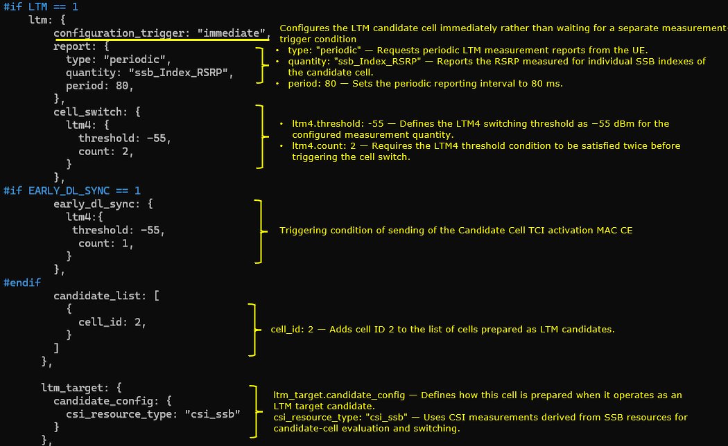

This block(nr_cell_default) defines the common radio configuration for both NR cells. It uses 30 kHz subcarrier spacing, 20 MHz bandwidth, two downlink antennas, and one uplink antenna. For TDD operation, the default pattern uses a 5 ms period with seven downlink slots, two uplink slots, and one special slot containing six downlink symbols and one uplink symbol.
The csi_rs block configures the CSI reference-signal resources and CSI reporting. Inside resource_auto, nzp_csi_rs_period is set to 80 ms for NZP-CSI-RS transmission. When LTM is enabled, ssb_set is set to true to include an SSB-related CSI resource set for candidate-cell beam measurement. Inside csi_report_config, report_config_type is set to periodic, period is set to 80 ms, and report_quantity is set to CRI_RI_PMI_CQI. For FR2, trs_presence is set to false, so TRS is not included in the resource_auto configuration.
The meas_config_desc block defines the general NR measurement configuration. It includes A1, A2, and A3 RSRP-based measurement conditions for normal measurement reporting and conventional handover operation. In this LTM test, the nr_ltm block is not configured inside meas_config_desc. Therefore, LTM candidate preparation is not controlled by a separate Layer 3 measurement-trigger condition. The candidate configuration is provided immediately by the gNB, and the actual cell switch is evaluated using the configured LTM Layer 1 measurement condition.
The nr_conditional_handover block is included only when CONDITIONAL_HO is set to 1 and is not used in this test. The meas_gap_config block sets pattern_id to 0, configuring the measurement-gap pattern available for inter-frequency or other measurements that require measurement gaps.
Configure ue-nr-sa-ltm.cfg as below
N_CELL is set to 2, NR_TDD is set to 1 for TDD operation, and CELL_BANDWIDTH is set to 20 MHz. N_ANTENNA_DL is set to 2 for 2x2 downlink MIMO, while N_ANTENNA_UL is set to 1. UE_COUNT is set to 1, and CHANNEL_SIM is set to 0 because the channel simulator is not used in this test.
The cell_groups block defines one NR cell group containing the RF configurations for both cells used in the LTM test. The parameter group_type is set to nr, and multi_ue is set to 1.
Inside the cells block, the first cell uses rf_port 0, band 78, dl_nr_arfcn 625400, and ssb_nr_arfcn 625400. The second cell uses rf_port 1, band 78, dl_nr_arfcn 626400, and ssb_nr_arfcn 626400. Both cells use the bandwidth defined by CELL_BANDWIDTH, 30 kHz SSB and data subcarrier spacing, and the antenna numbers defined by N_ANTENNA_DL and N_ANTENNA_UL.
The ue_list block defines the simulated UE identity and capability settings used for the LTM test. The parameter as_release is set to 18 so that the UE advertises an NR access-stratum release that supports LTM. The parameter ue_category is set to nr, ue_count uses the value defined by UE_COUNT, and ltm_support is set to true to enable LTM capability in the simulated UE. The parameter rrc_initial_selection is set to false so that the UE does not perform automatic initial cell selection based on the strongest detected cell.
Perform the test
The cell_phy command displays the physical-layer configuration of the two NR cells used in the LTM test. Cell 0x001 uses dl_nr_arfcn 625400 and ssb_nr_arfcn 625400, while cell 0x002 uses dl_nr_arfcn 626400 and ssb_nr_arfcn 626400. Both cells operate in band n78 with 20 MHz bandwidth and 30 kHz subcarrier spacing. Since both ARFCNs belong to the same NR band, this is an intra-frequency LTM scenario.
The cell command first confirms the initial downlink power condition. Cell 0x001 with PCI 501 has dl_gain set to 0.0 dB and acts as the serving cell, while cell 0x002 with PCI 502 has dl_gain set to -20.0 dB and is initially weaker.
The cell_gain 1 -20 command reduces the dl_gain of cell 0x001 to -20 dB, and the cell_gain 2 0 command increases the dl_gain of cell 0x002 to 0 dB. This reverses the relative received power of the two cells and creates the triggering condition for LTM. The UE then detects cell 0x002 as the stronger candidate and the configured LTM measurement condition can be satisfied.
The UE trace shows the LTM cell switch from cell 0x00 with RNTI 4601 to cell 0x01 with RNTI 4602. Before the switch, the UE remains connected to the original serving cell while its RSRP decreases to approximately -58.8 dBm. After the configured LTM condition is satisfied, the UE changes to the target cell and receives the new RNTI 4602. The RSRP then improves to approximately -37.1 dBm, confirming that the UE has completed the L1/L2 triggered mobility procedure and is operating on the stronger target cell.
Log Analysis
I follow the RRC and MAC messages from UE capability exchange through candidate preparation and the LTM cell switch. The final entries verify random access and RRC completion on the destination cell.
I first check the UE capability enquiry sent on cell 1. The request uses rat-Type nr and includes bandNR 78 in frequencyBandListFilter. This asks the UE for capability information relevant to band n78.
The enquiry uses rrc-TransactionIdentifier 0. The UE capability information response follows 30 ms after the enquiry.
The gNB uses this enquiry to learn which radio features and configurations the UE supports before choosing the settings for the connection.
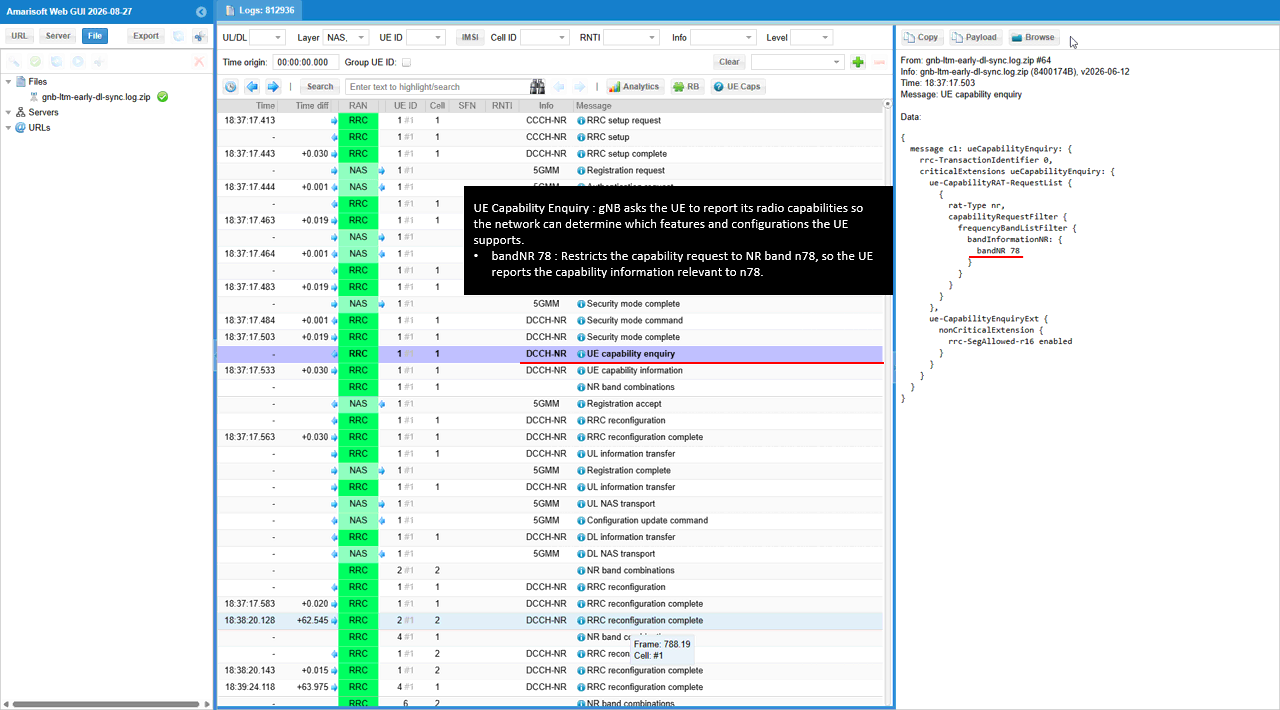
Open UE Caps to inspect the decoded capability summary for UE 1. NR bands contains 78. The CA combination list includes DL N78A + UL N78A twice, DL N78B + UL N78B, and DL N78A + UL N78A.
The first combination contains two n78 component carriers with DL and UL bandwidth class A. The other entries provide the class B combination and the single-carrier class A combination. These are reported capabilities, not a list of carriers active during the test.
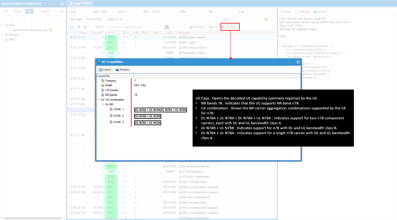
In UE capability information, I check ltm-MCG-IntraFreq-r18 supported and the ltm-MAC-CE-JointTCI-r18 block. These identify intra-frequency LTM support in the MCG and support for Joint TCI signaling through MAC CE.
The Joint TCI block contains qcl-Resource-r18 ssb. maxNumberJointTCI-PerCell-r18 and maxNumberJointTCI-AcrossCells-r18 are both 8. The UE therefore reports limits of eight Joint TCI states per cell and eight across cells.
The gNB uses the reported capabilities to check whether the UE supports the LTM features needed for this test. ltm-MCG-IntraFreq-r18 identifies the Release 18 capability. With qcl-Resource-r18 set to ssb, the UE can use an SSB as the QCL reference for Joint TCI.
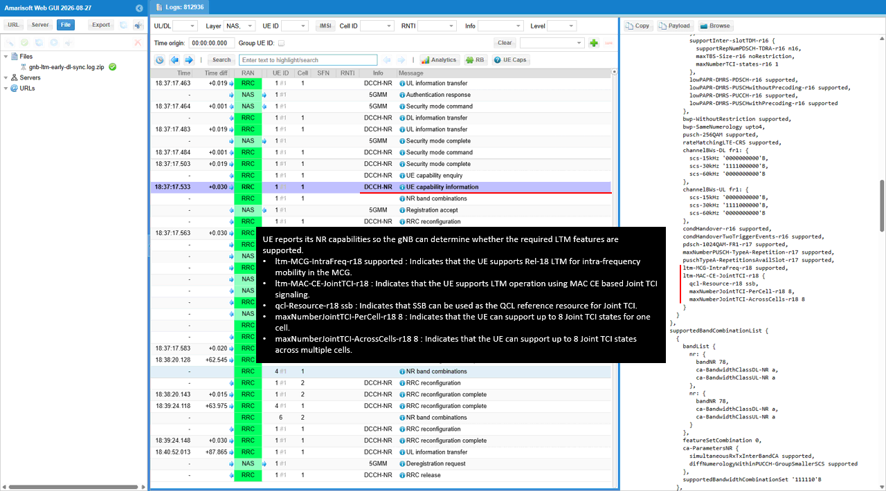
I also check ltm-InterFreq-r18 supported under measAndMobParametersCommon. This declares inter-frequency LTM support in addition to the intra-frequency capability checked earlier.
This field belongs to the same UE capability information response. Keep this field in mind when checking the different serving and candidate SSB frequencies in the following RRC configuration.
The ltm-InterFreq-r18 field specifically identifies support for Release 18 LTM between frequencies.
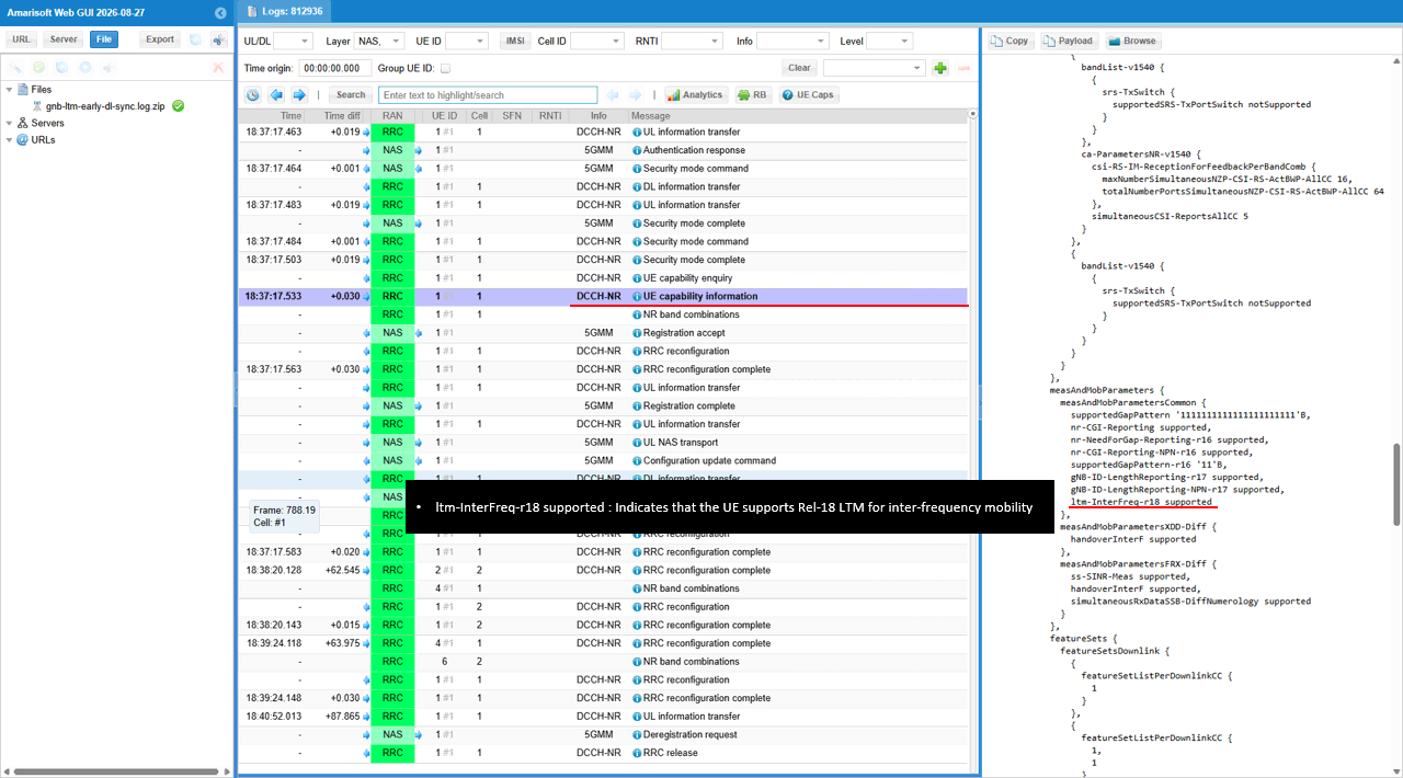
The first RRC reconfiguration contains measObjectId 1 with measObjectNR. ssbFrequency is 625400, ssbSubcarrierSpacing is kHz30 and freqBandIndicatorNR is 78. The measurement object therefore identifies an n78 SSB using 30 kHz subcarrier spacing.
In smtc1, periodicityAndOffset is sf20: 0 and duration is sf1. The SSB measurement window repeats every 20 ms with offset 0 and lasts 1 ms.
referenceSignalConfig includes ssb-ConfigMobility with deriveSSB-IndexFromCell FALSE. quantityConfigIndex is 1. This message has measGapConfig set to gapUE release; the later reconfiguration sets up the measurement gap.
The gNB can use an NR measurement object to define measurements of a serving or LTM candidate frequency. measObjectNR specifies the NR frequency and SSB measurement conditions, while smtc1 defines when the UE performs those measurements.
referenceSignalConfig selects the measurement reference signal, and ssb-ConfigMobility configures SSB-based mobility measurements. quantityConfigIndex 1 points to the measurement quantity and filter configuration to apply.
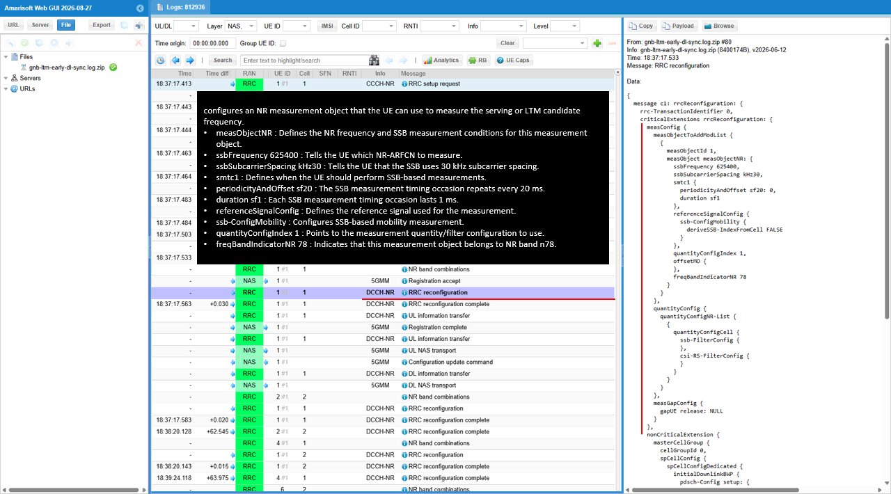
The later RRC reconfiguration sets measConfig.measGapConfig to gapUE setup. gapOffset is 4, mgl is ms6 and mgrp is ms40. This configures a 6 ms measurement gap repeating every 40 ms.
mgta is ms0dot5, giving the gap a 0.5 ms timing advance. These gap settings provide measurement time for evaluating the LTM candidate.
measGapConfig defines the measurement gap pattern, and gapUE setup applies it at UE level. gapOffset 4 determines where the gap begins within that pattern.
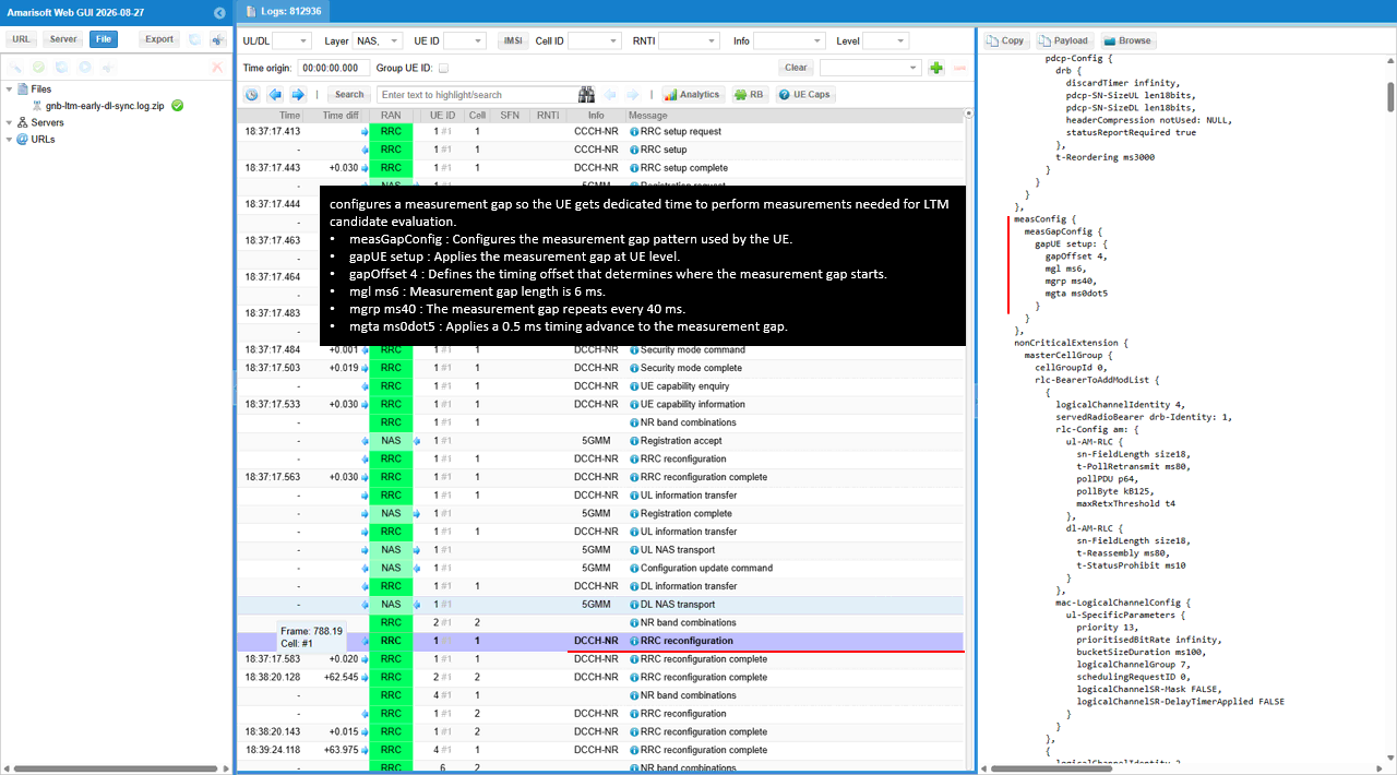
Under csi-MeasConfig setup, ltm-CSI-ReportConfigToAddModList-r18 adds report configuration 1. ltm-ResourcesForChannelMeasurement-r18 is 0, linking this report to LTM CSI resource configuration 0.
ltm-ReportConfigType-r18 is periodic-r18 with reportSlotConfig-r18 slots80: 29. The report repeats every 80 slots with offset 29. pucch-CSI-ResourceList-r18 selects uplinkBandwidthPartId 0 and pucch-Resource 14.
In ltm-ReportContent-r18, nrofReportedCells-r18 and nrofReportedRS-PerCell-r18 are both n1. Each report contains one cell and one reference signal for that cell.
This CSI configuration lets the UE evaluate LTM candidates and report the best candidate and reference signal information. ltm-CSI-ReportConfigToAddModList-r18 can add or update an LTM-specific CSI report configuration.
ltm-CSI-ReportConfigId-r18 1 identifies this particular report configuration. The UE transmits it on uplink BWP 0 using PUCCH resource 14.
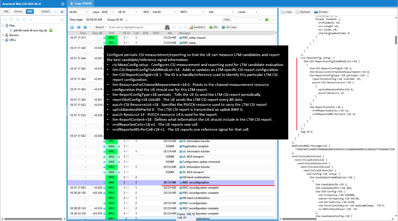
ltm-CandidateToAddModList-r18 adds ltm-CandidateId-r18 1 with ltm-CandidatePCI-r18 502. In ltm-SSB-Config-r18, ssb-Frequency-r18 is 626400 and subcarrierSpacing-r18 is kHz30. This candidate SSB frequency differs from the measurement object frequency 625400 checked earlier.
ssb-Periodicity-r18 is ms20 and ssb-PositionsInBurst-r18 uses mediumBitmap: 'F0'H. ss-PBCH-BlockPower-r18 is -56. These fields provide the candidate SSB timing, transmitted SSB positions and power information.
ltm-CandidateConfig-r18 contains the prepared RRC reconfiguration for the candidate. Its radioBearerConfig includes SRB identities 1 and 2, plus DRB identity 1. The DRB is associated with pdu-Session 1.
The gNB uses ltm-CandidateToAddModList-r18 to add or update candidates in the UE. ltm-CandidateId-r18 1 lets both sides refer to this candidate later without sending its full configuration again.
ltm-SSB-Config-r18 tells the UE which SSB to use for candidate identification, synchronization and measurement. The ms20 periodicity means the candidate SSB burst repeats every 20 ms.
When this candidate is selected, the UE can apply the radio configuration already supplied in ltm-CandidateConfig-r18. srb-ToAddModList defines its SRBs, and drb-ToAddModList defines its DRBs.
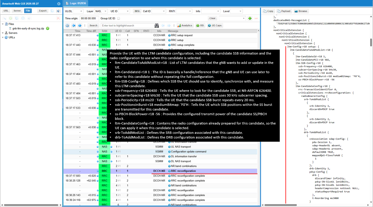
In the candidate spCellConfig, reconfigurationWithSync contains spCellConfigCommon with physCellId 502. The downlink frequency configuration sets absoluteFrequencySSB to 626400 and frequencyBandList to 78.
absoluteFrequencyPointA is 625788. The scs-SpecificCarrierList entry uses offsetToCarrier 0, subcarrierSpacing kHz30 and carrierBandwidth 51. This defines a candidate carrier grid spanning 51 PRBs.
The initialDownlinkBWP uses locationAndBandwidth 13750 and subcarrierSpacing kHz30. Its pdcch-ConfigCommon includes controlResourceSetZero 2 and searchSpaceZero 0.
reconfigurationWithSync supplies the settings for synchronizing to the candidate and applying its serving-cell configuration. spCellConfigCommon provides the common configuration for the candidate SpCell. physCellId identifies its PCI, and absoluteFrequencySSB locates its SSB.
Point A is the frequency reference for the candidate resource grid. The candidate configuration also includes BWP setup for both DL and UL.
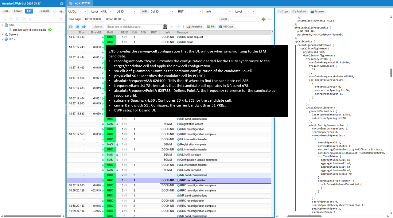
ltm-ConfigComplete-r18 is true. The ltm-TCI-Info-r18 block includes ltm-DL-OrJointTCI-StateToAddModList-r18 with tci-StateId-r18 values 0 through 3.
Each state uses qcl-Type-r18 typeD and references the SSB with the same index. State 0 references ssb-Index 0, continuing through state 3 and ssb-Index 3. These SSBs provide the spatial QCL references for the configured states.
pathlossReferenceRS-Id-r18 also runs from 0 through 3, matching the corresponding state IDs. You can follow these references into the pathloss reference configuration below.
ltm-ConfigComplete-r18 true marks the supplied LTM configuration as complete and usable by the UE. ltm-TCI-Info-r18 prepares TCI states and QCL relationships for later beam or cell switching.
ltm-DL-OrJointTCI-StateToAddModList-r18 adds or updates the DL or Joint TCI states available for selection during LTM. Each tci-StateId-r18 is a reference identifying one state. Its pathlossReferenceRS-Id-r18 selects the pathloss reference signal for UL power-control calculations.
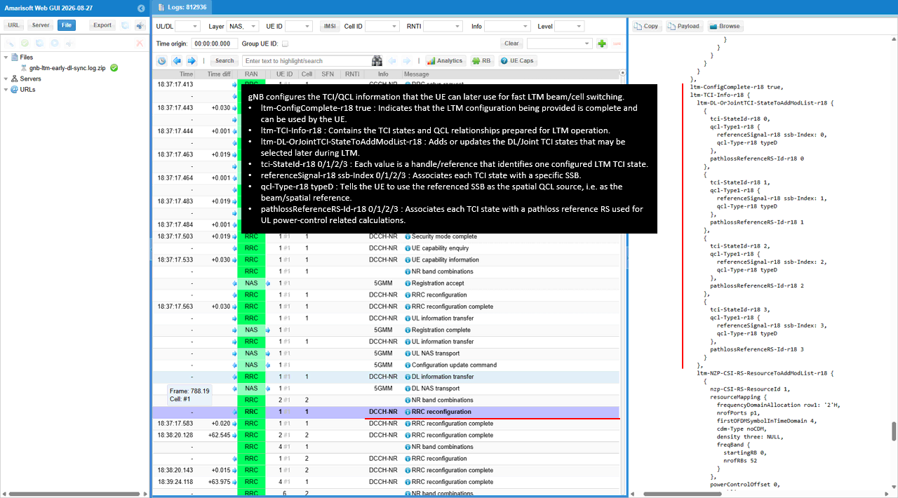
ltm-NZP-CSI-RS-ResourceToAddModList-r18 defines nzp-CSI-RS-ResourceId 1, 2 and 3 in this part of the configuration. Each uses frequencyDomainAllocation row1: '2'H, nrofPorts p1, cdm-Type noCDM and density three.
The frequency allocation starts at startingRB 0 and spans nrofRBs 52. scramblingID is 502 and powerControlOffset is 0 for these resources.
Resources 1 and 2 use periodicityAndOffset slots80: 2, with firstOFDMSymbolInTimeDomain 4 and 8 respectively. Resource 3 uses slots80: 3 and starts at symbol 4. These settings separate the resources by their slot offset and starting symbol.
The gNB supplies these NZP CSI-RS resources for LTM candidate and beam measurements and reporting. Each nzp-CSI-RS-ResourceId identifies one resource. resourceMapping defines its time and frequency placement.
frequencyDomainAllocation selects the frequency-domain pattern, and nrofPorts p1 configures a single CSI-RS port. scramblingID 502 selects the ID used for the CSI-RS sequence. The slots80 periodicity repeats each resource every 80 slots at its configured offset.
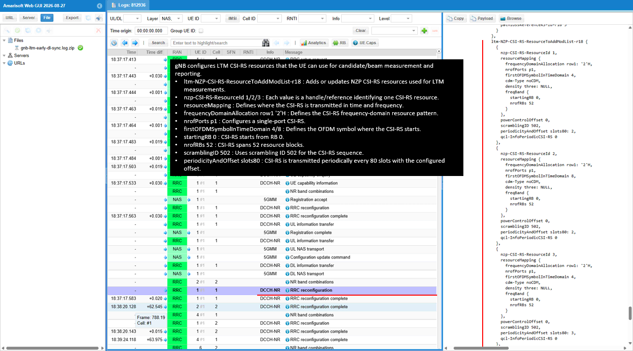
nzp-CSI-RS-ResourceId 4 uses firstOFDMSymbolInTimeDomain 8 and periodicityAndOffset slots80: 3. Its mapping keeps row1: '2'H, nrofPorts p1, startingRB 0 and nrofRBs 52. scramblingID remains 502.
ltm-NZP-CSI-RS-ResourceSetToAddModList-r18 then defines nzp-CSI-RS-ResourceSetId 1. Its nzp-CSI-RS-Resources list contains 1, 2, 3 and 4. trs-Info is true for this resource set.
nzp-CSI-RS-ResourceId 4 identifies the fourth CSI-RS resource. ltm-NZP-CSI-RS-ResourceSetToAddModList-r18 adds or updates an LTM CSI-RS resource set, with nzp-CSI-RS-ResourceSetId 1 identifying this set.
The resource list groups resources 1 through 4 into the same LTM measurement set. trs-Info true marks the set as having TRS-related properties.
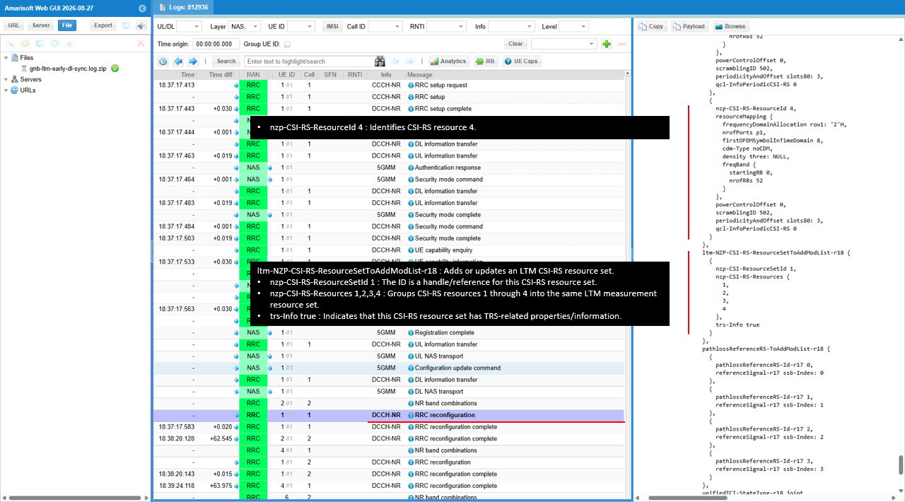
ltm-CSI-ResourceConfigToAddModList-r18 defines ltm-CSI-ResourceConfigId-r18 0. This is the resource configuration referenced by the periodic LTM CSI report.
Within ltm-SSB-ResourceSet-r18, ltm-SSB-ResourceList-r18 contains 0, 1, 2 and 3. The corresponding ltm-CandidateIdList-r18 entries are all 1. All four SSB resources therefore belong to LTM candidate 1.
The pathloss reference entries pair pathlossReferenceRS-Id-r17 0 through 3 with matching ssb-Index values. unifiedTCI-StateType-r18 is joint.
The gNB uses this mapping to tell the UE which measurement resources belong to each LTM candidate. ltm-CSI-ResourceConfigToAddModList-r18 can add or update that resource configuration. ltm-CSI-ResourceConfigId-r18 0 is the reference used to identify it.
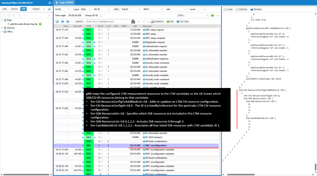
The MAC log contains Candidate Cell TCI States Activation/Deactivation. The decoded command identifies Candidate ID: 1 and Codepoint 1: DL or Joint TCI State 3.
This activates the candidate TCI information for early downlink synchronization before the cell switch. State 3 refers back to the prepared TCI configuration. The surrounding PHY entries still use cell 1 and RNTI 0x4601.
Candidate Cell TCI States Activation/Deactivation is a MAC CE for activating or deactivating previously configured candidate TCI states. It allows the UE to select a prepared spatial/QCL configuration without another RRC reconfiguration.
Candidate ID 1 refers to the candidate configured earlier, while Codepoint 1 identifies the TCI activation codepoint carried by this MAC CE. DL or Joint TCI State 3 selects the corresponding prepared beam and QCL reference.
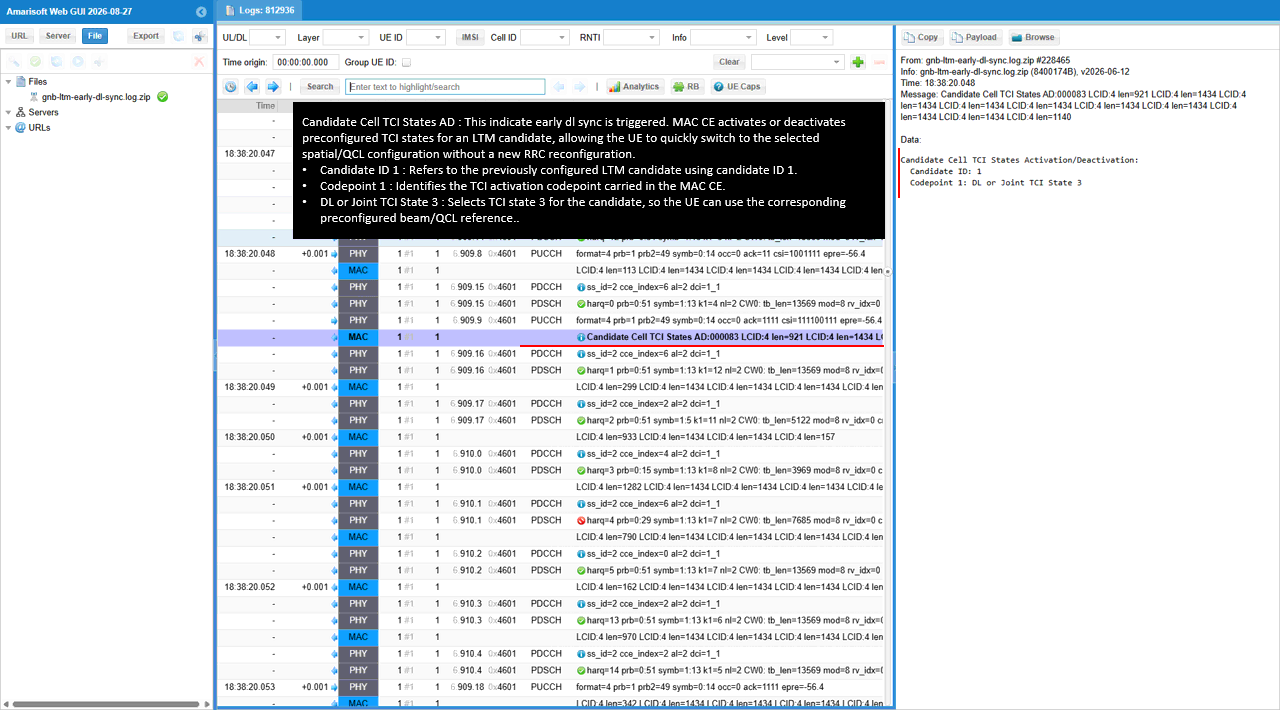
The MAC log reports that the LTM triggering condition is met and the cell switch command will be issued. This occurs after the Candidate Cell TCI activation.
The LTM Cell Switch Cmd follows 5 ms after the trigger entry. I use these two entries to separate the trigger decision from transmission of the command.
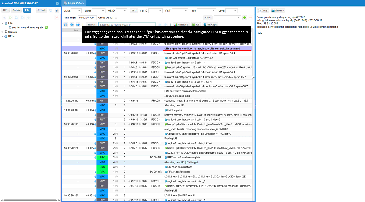
The LTM Cell Switch Command contains Target Config ID: 0 and TCI state ID: 3. The UE uses these identifiers to select the prepared target configuration and TCI state.
Timing Advance Command reads "no valid timing adjustment is available". The command therefore does not supply a usable timing correction for the target. The following log entries include PRACH and RAR on cell 2.
The MAC log also records "LTM cell switch command transmitted" before setting the source UE to stopped state. Check this entry separately from the earlier trigger decision.
This MAC CE directs the UE to switch to a previously configured LTM candidate using the prepared target parameters. TCI state ID 3 selects the target beam reference for the switch.
Because no valid timing adjustment is supplied, the UE still needs to establish or adjust its uplink timing toward the target. In this run, it performs random access on the destination cell.
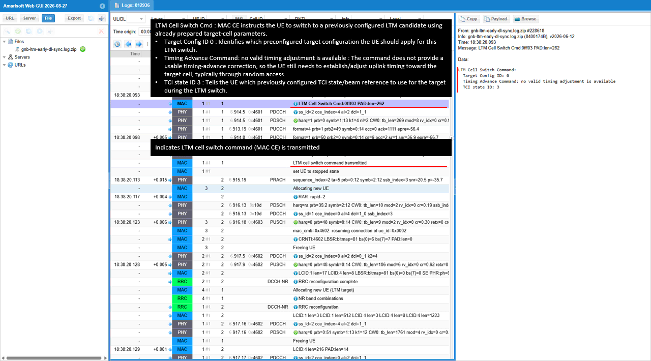
The UE performs PRACH on cell 2. The PRACH entry has sequence_index=2 and ssb_index=3. The target responds with RAR: rapid=2.
After the uplink exchange, the MAC log reports mac_crnti=0x4602 and resumes the connection. Subsequent PHY entries on cell 2 use RNTI 0x4602.
RRC reconfiguration complete appears on cell 2. This confirms completion on the destination cell after random access. The following entries prepare another LTM target configuration.
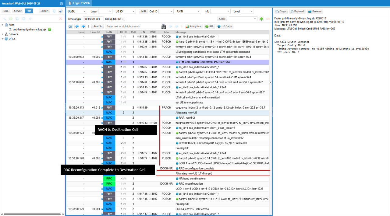
RRC / NAS Signaling
RrcReconfiguration
: This is the RrcReconfiguration message sent by eNB to configure LTM (
{
message c1: rrcReconfiguration: {
rrc-TransactionIdentifier 0,
criticalExtensions rrcReconfiguration: {
radioBearerConfig {
srb-ToAddModList {
{
srb-Identity 2
}
},
drb-ToAddModList {
{
cnAssociation sdap-Config: {
pdu-Session 1,
sdap-HeaderDL absent,
sdap-HeaderUL present,
defaultDRB TRUE,
mappedQoS-FlowsToAdd {
1
}
},
drb-Identity 1,
pdcp-Config {
drb {
discardTimer infinity,
pdcp-SN-SizeUL len18bits,
pdcp-SN-SizeDL len18bits,
headerCompression notUsed: NULL,
statusReportRequired true
},
t-Reordering ms3000
}
}
}
},
nonCriticalExtension {
masterCellGroup {
cellGroupId 0,
rlc-BearerToAddModList {
{
logicalChannelIdentity 4,
servedRadioBearer drb-Identity: 1,
rlc-Config am: {
ul-AM-RLC {
sn-FieldLength size18,
t-PollRetransmit ms80,
pollPDU p64,
pollByte kB125,
maxRetxThreshold t32
},
dl-AM-RLC {
sn-FieldLength size18,
t-Reassembly ms80,
t-StatusProhibit ms10
}
},
mac-LogicalChannelConfig {
ul-SpecificParameters {
priority 15,
prioritisedBitRate kBps8,
bucketSizeDuration ms100,
logicalChannelGroup 7,
schedulingRequestID 0,
logicalChannelSR-Mask FALSE,
logicalChannelSR-DelayTimerApplied FALSE
}
}
},
{
logicalChannelIdentity 2,
servedRadioBearer srb-Identity: 2,
mac-LogicalChannelConfig {
ul-SpecificParameters {
priority 3,
prioritisedBitRate infinity,
bucketSizeDuration ms5,
logicalChannelGroup 0,
schedulingRequestID 0,
logicalChannelSR-Mask FALSE,
logicalChannelSR-DelayTimerApplied FALSE
}
}
}
},
spCellConfig {
spCellConfigDedicated {
uplinkConfig {
initialUplinkBWP {
pucch-Config setup: {
resourceToAddModList {
{
pucch-ResourceId 6,
startingPRB 2,
format format3: {
nrofPRBs 1,
nrofSymbols 14,
startingSymbolIndex 0
}
}
}
}
}
},
csi-MeasConfig setup: {
ltm-CSI-ReportConfigToAddModList-r18 {
{
ltm-CSI-ReportConfigId-r18 1,
ltm-ResourcesForChannelMeasurement-r18 0,
ltm-ReportConfigType-r18 periodic-r18: {
reportSlotConfig-r18 slots80: 29,
pucch-CSI-ResourceList-r18 {
{
uplinkBandwidthPartId 0,
pucch-Resource 6
}
}
},
ltm-ReportContent-r18 {
nrOfReportedCells-r18 n1,
nrOfReportedRS-PerCell-r18 n1
}
}
}
},
tag-Id 0
}
}
},
dedicatedNAS-MessageList {
'7E0294C61343037E00680100652E0101C211000901000631300101FF010606271004B71B5932290501C0A80202220101817900060120410101097B00188080210A0300000A810608080808000D0408080808001100251B0764656661756C74066D6E63303031066D636330303104677072731201'H
},
nonCriticalExtension {
nonCriticalExtension {
nonCriticalExtension {
nonCriticalExtension {
nonCriticalExtension {
ltm-Config-r18 setup: {
ltm-CandidateToAddModList-r18 {
{
ltm-CandidateId-r18 1,
ltm-CandidatePCI-r18 502,
ltm-SSB-Config-r18 {
ssb-Frequency-r18 626400,
subcarrierSpacing-r18 kHz30,
ssb-Periodicity-r18 ms20,
ssb-PositionsInBurst-r18 mediumBitmap: 'F0'H,
ss-PBCH-BlockPower-r18 -45
},
ltm-CandidateConfig-r18 {
rrc-TransactionIdentifier 0,
criticalExtensions rrcReconfiguration: {
radioBearerConfig {
srb-ToAddModList {
{
srb-Identity 1,
discardOnPDCP true
},
{
srb-Identity 2,
discardOnPDCP true
}
},
drb-ToAddModList {
{
cnAssociation sdap-Config: {
pdu-Session 1,
sdap-HeaderDL absent,
sdap-HeaderUL present,
defaultDRB TRUE,
mappedQoS-FlowsToAdd {
1
}
},
drb-Identity 1,
pdcp-Config {
drb {
discardTimer infinity,
pdcp-SN-SizeUL len18bits,
pdcp-SN-SizeDL len18bits,
headerCompression notUsed: NULL,
statusReportRequired true
},
t-Reordering ms3000
}
}
}
},
measConfig {
measObjectToAddModList {
{
measObjectId 1,
measObject measObjectNR: {
ssbFrequency 626400,
ssbSubcarrierSpacing kHz30,
smtc1 {
periodicityAndOffset sf20: 0,
duration sf1
},
referenceSignalConfig {
ssb-ConfigMobility {
deriveSSB-IndexFromCell FALSE
}
},
quantityConfigIndex 1,
offsetMO {
},
freqBandIndicatorNR 78
}
}
},
quantityConfig {
quantityConfigNR-List {
{
quantityConfigCell {
ssb-FilterConfig {
},
csi-RS-FilterConfig {
}
}
}
}
},
measGapConfig {
gapUE release: NULL
}
},
nonCriticalExtension {
masterCellGroup {
cellGroupId 0,
rlc-BearerToAddModList {
{
logicalChannelIdentity 4,
servedRadioBearer drb-Identity: 1,
rlc-Config am: {
ul-AM-RLC {
sn-FieldLength size18,
t-PollRetransmit ms80,
pollPDU p64,
pollByte kB125,
maxRetxThreshold t32
},
dl-AM-RLC {
sn-FieldLength size18,
t-Reassembly ms80,
t-StatusProhibit ms10
}
},
mac-LogicalChannelConfig {
ul-SpecificParameters {
priority 15,
prioritisedBitRate kBps8,
bucketSizeDuration ms100,
logicalChannelGroup 7,
schedulingRequestID 0,
logicalChannelSR-Mask FALSE,
logicalChannelSR-DelayTimerApplied FALSE
}
}
},
{
logicalChannelIdentity 1,
servedRadioBearer srb-Identity: 1,
reestablishRLC true,
mac-LogicalChannelConfig {
ul-SpecificParameters {
priority 1,
prioritisedBitRate infinity,
bucketSizeDuration ms5,
logicalChannelGroup 0,
schedulingRequestID 0,
logicalChannelSR-Mask FALSE,
logicalChannelSR-DelayTimerApplied FALSE
}
}
},
{
logicalChannelIdentity 2,
servedRadioBearer srb-Identity: 2,
reestablishRLC true,
mac-LogicalChannelConfig {
ul-SpecificParameters {
priority 3,
prioritisedBitRate infinity,
bucketSizeDuration ms5,
logicalChannelGroup 0,
schedulingRequestID 0,
logicalChannelSR-Mask FALSE,
logicalChannelSR-DelayTimerApplied FALSE
}
}
}
},
mac-CellGroupConfig {
schedulingRequestConfig {
schedulingRequestToAddModList {
{
schedulingRequestId 0,
sr-TransMax n64
}
}
},
bsr-Config {
periodicBSR-Timer sf20,
retxBSR-Timer sf320
},
tag-Config {
tag-ToAddModList {
{
tag-Id 0,
timeAlignmentTimer infinity
}
}
},
phr-Config setup: {
phr-PeriodicTimer sf500,
phr-ProhibitTimer sf200,
phr-Tx-PowerFactorChange dB3,
multiplePHR FALSE,
dummy FALSE,
phr-Type2OtherCell FALSE,
phr-ModeOtherCG real
},
skipUplinkTxDynamic FALSE
},
physicalCellGroupConfig {
p-NR-FR1 10,
pdsch-HARQ-ACK-Codebook dynamic
},
spCellConfig {
reconfigurationWithSync {
spCellConfigCommon {
physCellId 502,
downlinkConfigCommon {
frequencyInfoDL {
absoluteFrequencySSB 626400,
frequencyBandList {
78
},
absoluteFrequencyPointA 625788,
scs-SpecificCarrierList {
{
offsetToCarrier 0,
subcarrierSpacing kHz30,
carrierBandwidth 51
}
}
},
initialDownlinkBWP {
genericParameters {
locationAndBandwidth 13750,
subcarrierSpacing kHz30
},
pdcch-ConfigCommon setup: {
controlResourceSetZero 2,
searchSpaceZero 0,
commonSearchSpaceList {
{
searchSpaceId 1,
controlResourceSetId 0,
monitoringSlotPeriodicityAndOffset sl1: NULL,
monitoringSymbolsWithinSlot '10000000000000'B,
nrofCandidates {
aggregationLevel1 n0,
aggregationLevel2 n0,
aggregationLevel4 n4,
aggregationLevel8 n0,
aggregationLevel16 n0
},
searchSpaceType common: {
dci-Format0-0-AndFormat1-0 {
}
}
}
},
searchSpaceSIB1 0,
searchSpaceOtherSystemInformation 1,
pagingSearchSpace 1,
ra-SearchSpace 1
},
pdsch-ConfigCommon setup: {
pdsch-TimeDomainAllocationList {
{
mappingType typeA,
startSymbolAndLength 40
},
{
mappingType typeA,
startSymbolAndLength 57
}
}
}
}
},
uplinkConfigCommon {
frequencyInfoUL {
scs-SpecificCarrierList {
{
offsetToCarrier 0,
subcarrierSpacing kHz30,
carrierBandwidth 51
}
},
p-Max 10
},
initialUplinkBWP {
genericParameters {
locationAndBandwidth 13750,
subcarrierSpacing kHz30
},
rach-ConfigCommon setup: {
rach-ConfigGeneric {
prach-ConfigurationIndex 160,
msg1-FDM one,
msg1-FrequencyStart 0,
zeroCorrelationZoneConfig 15,
preambleReceivedTargetPower -110,
preambleTransMax n7,
powerRampingStep dB4,
ra-ResponseWindow sl20
},
ssb-perRACH-OccasionAndCB-PreamblesPerSSB one: n8,
ra-ContentionResolutionTimer sf64,
prach-RootSequenceIndex l139: 1,
msg1-SubcarrierSpacing kHz30,
restrictedSetConfig unrestrictedSet
},
pusch-ConfigCommon setup: {
pusch-TimeDomainAllocationList {
{
k2 7,
mappingType typeA,
startSymbolAndLength 27
},
{
k2 4,
mappingType typeA,
startSymbolAndLength 27
},
{
k2 2,
mappingType typeA,
startSymbolAndLength 27
}
},
p0-NominalWithGrant -90
},
pucch-ConfigCommon setup: {
pucch-ResourceCommon 11,
pucch-GroupHopping neither,
p0-nominal -96
}
},
dummy ms500
},
ssb-PositionsInBurst mediumBitmap: 'F0'H,
ssb-periodicityServingCell ms20,
dmrs-TypeA-Position pos2,
ssbSubcarrierSpacing kHz30,
tdd-UL-DL-ConfigurationCommon {
referenceSubcarrierSpacing kHz30,
pattern1 {
dl-UL-TransmissionPeriodicity ms5,
nrofDownlinkSlots 7,
nrofDownlinkSymbols 6,
nrofUplinkSlots 2,
nrofUplinkSymbols 1
}
},
ss-PBCH-BlockPower -45
},
newUE-Identity 17922,
t304 ms1000,
smtc {
periodicityAndOffset sf20: 0,
duration sf1
}
},
spCellConfigDedicated {
initialDownlinkBWP {
pdcch-Config setup: {
controlResourceSetToAddModList {
{
controlResourceSetId 2,
frequencyDomainResources '111111110000000000000000000000000000000000000'B,
duration 1,
cce-REG-MappingType nonInterleaved: NULL,
precoderGranularity sameAsREG-bundle
}
},
searchSpacesToAddModList {
{
searchSpaceId 2,
controlResourceSetId 2,
monitoringSlotPeriodicityAndOffset sl1: NULL,
monitoringSymbolsWithinSlot '10000000000000'B,
nrofCandidates {
aggregationLevel1 n0,
aggregationLevel2 n4,
aggregationLevel4 n0,
aggregationLevel8 n0,
aggregationLevel16 n0
},
searchSpaceType ue-Specific: {
dci-Formats formats0-1-And-1-1
}
}
}
},
pdsch-Config setup: {
dmrs-DownlinkForPDSCH-MappingTypeA setup: {
dmrs-AdditionalPosition pos1
},
tci-StatesToAddModList {
{
tci-StateId 0,
qcl-Type1 {
referenceSignal ssb: 0,
qcl-Type typeD
}
}
},
resourceAllocation resourceAllocationType1,
rbg-Size config1,
mcs-Table qam256,
prb-BundlingType staticBundling: {
bundleSize wideband
},
zp-CSI-RS-ResourceToAddModList {
{
zp-CSI-RS-ResourceId 0,
resourceMapping {
frequencyDomainAllocation row4: '010'B,
nrofPorts p4,
firstOFDMSymbolInTimeDomain 4,
cdm-Type fd-CDM2,
density one: NULL,
freqBand {
startingRB 0,
nrofRBs 52
}
},
periodicityAndOffset slots80: 2
}
},
p-ZP-CSI-RS-ResourceSet setup: {
zp-CSI-RS-ResourceSetId 0,
zp-CSI-RS-ResourceIdList {
0
}
}
}
},
firstActiveDownlinkBWP-Id 0,
uplinkConfig {
initialUplinkBWP {
pucch-Config setup: {
resourceSetToAddModList {
{
pucch-ResourceSetId 0,
resourceList {
0,
1,
2
}
},
{
pucch-ResourceSetId 1,
resourceList {
3
}
}
},
resourceToAddModList {
{
pucch-ResourceId 0,
startingPRB 1,
format format1: {
initialCyclicShift 2,
nrofSymbols 14,
startingSymbolIndex 0,
timeDomainOCC 0
}
},
{
pucch-ResourceId 1,
startingPRB 1,
format format1: {
initialCyclicShift 6,
nrofSymbols 14,
startingSymbolIndex 0,
timeDomainOCC 0
}
},
{
pucch-ResourceId 2,
startingPRB 1,
format format1: {
initialCyclicShift 10,
nrofSymbols 14,
startingSymbolIndex 0,
timeDomainOCC 0
}
},
{
pucch-ResourceId 3,
startingPRB 49,
format format3: {
nrofPRBs 1,
nrofSymbols 14,
startingSymbolIndex 0
}
},
{
pucch-ResourceId 4,
startingPRB 1,
format format1: {
initialCyclicShift 2,
nrofSymbols 14,
startingSymbolIndex 0,
timeDomainOCC 1
}
},
{
pucch-ResourceId 5,
startingPRB 2,
format format3: {
nrofPRBs 1,
nrofSymbols 14,
startingSymbolIndex 0
}
}
},
format1 setup: {
},
format3 setup: {
maxCodeRate zeroDot25,
simultaneousHARQ-ACK-CSI true
},
schedulingRequestResourceToAddModList {
{
schedulingRequestResourceId 1,
schedulingRequestID 0,
periodicityAndOffset sl40: 8,
resource 4
}
},
dl-DataToUL-ACK {
8,
7,
6,
5,
4,
12,
11
}
},
pusch-Config setup: {
txConfig codebook,
dmrs-UplinkForPUSCH-MappingTypeA setup: {
dmrs-AdditionalPosition pos1,
transformPrecodingDisabled {
}
},
pusch-PowerControl {
msg3-Alpha alpha1,
p0-AlphaSets {
{
p0-PUSCH-AlphaSetId 0,
p0 0,
alpha alpha1
}
},
pathlossReferenceRSToAddModList {
{
pusch-PathlossReferenceRS-Id 0,
referenceSignal ssb-Index: 0
}
},
sri-PUSCH-MappingToAddModList {
{
sri-PUSCH-PowerControlId 0,
sri-PUSCH-PathlossReferenceRS-Id 0,
sri-P0-PUSCH-AlphaSetId 0,
sri-PUSCH-ClosedLoopIndex i0
}
}
},
resourceAllocation resourceAllocationType1,
codebookSubset nonCoherent,
maxRank 1,
uci-OnPUSCH setup: {
betaOffsets semiStatic: {
betaOffsetACK-Index1 9,
betaOffsetACK-Index2 9,
betaOffsetACK-Index3 9,
betaOffsetCSI-Part1-Index1 7,
betaOffsetCSI-Part1-Index2 7,
betaOffsetCSI-Part2-Index1 7,
betaOffsetCSI-Part2-Index2 7
},
scaling f1
}
},
srs-Config setup: {
srs-ResourceSetToAddModList {
{
srs-ResourceSetId 0,
srs-ResourceIdList {
0
},
resourceType aperiodic: {
aperiodicSRS-ResourceTrigger 1,
slotOffset 7
},
usage codebook,
p0 -90,
pathlossReferenceRS ssb-Index: 0
}
},
srs-ResourceToAddModList {
{
srs-ResourceId 0,
nrofSRS-Ports port1,
transmissionComb n2: {
combOffset-n2 0,
cyclicShift-n2 0
},
resourceMapping {
startPosition 0,
nrofSymbols n1,
repetitionFactor n1
},
freqDomainPosition 0,
freqDomainShift 5,
freqHopping {
c-SRS 11,
b-SRS 3,
b-hop 0
},
groupOrSequenceHopping neither,
resourceType aperiodic: {
},
sequenceId 502
}
}
}
},
firstActiveUplinkBWP-Id 0,
pusch-ServingCellConfig setup: {
}
},
pdcch-ServingCellConfig setup: {
},
pdsch-ServingCellConfig setup: {
nrofHARQ-ProcessesForPDSCH n16,
maxMIMO-Layers 2
},
csi-MeasConfig setup: {
nzp-CSI-RS-ResourceToAddModList {
{
nzp-CSI-RS-ResourceId 0,
resourceMapping {
frequencyDomainAllocation other: '000100'B,
nrofPorts p2,
firstOFDMSymbolInTimeDomain 3,
cdm-Type fd-CDM2,
density one: NULL,
freqBand {
startingRB 0,
nrofRBs 52
}
},
powerControlOffset 0,
scramblingID 502,
periodicityAndOffset slots80: 2,
qcl-InfoPeriodicCSI-RS 0
},
{
nzp-CSI-RS-ResourceId 1,
resourceMapping {
frequencyDomainAllocation row1: '2'H,
nrofPorts p1,
firstOFDMSymbolInTimeDomain 4,
cdm-Type noCDM,
density three: NULL,
freqBand {
startingRB 0,
nrofRBs 52
}
},
powerControlOffset 0,
scramblingID 502,
periodicityAndOffset slots80: 2,
qcl-InfoPeriodicCSI-RS 0
},
{
nzp-CSI-RS-ResourceId 2,
resourceMapping {
frequencyDomainAllocation row1: '2'H,
nrofPorts p1,
firstOFDMSymbolInTimeDomain 8,
cdm-Type noCDM,
density three: NULL,
freqBand {
startingRB 0,
nrofRBs 52
}
},
powerControlOffset 0,
scramblingID 502,
periodicityAndOffset slots80: 2,
qcl-InfoPeriodicCSI-RS 0
},
{
nzp-CSI-RS-ResourceId 3,
resourceMapping {
frequencyDomainAllocation row1: '2'H,
nrofPorts p1,
firstOFDMSymbolInTimeDomain 4,
cdm-Type noCDM,
density three: NULL,
freqBand {
startingRB 0,
nrofRBs 52
}
},
powerControlOffset 0,
scramblingID 502,
periodicityAndOffset slots80: 3,
qcl-InfoPeriodicCSI-RS 0
},
{
nzp-CSI-RS-ResourceId 4,
resourceMapping {
frequencyDomainAllocation row1: '2'H,
nrofPorts p1,
firstOFDMSymbolInTimeDomain 8,
cdm-Type noCDM,
density three: NULL,
freqBand {
startingRB 0,
nrofRBs 52
}
},
powerControlOffset 0,
scramblingID 502,
periodicityAndOffset slots80: 3,
qcl-InfoPeriodicCSI-RS 0
}
},
nzp-CSI-RS-ResourceSetToAddModList {
{
nzp-CSI-ResourceSetId 0,
nzp-CSI-RS-Resources {
0
}
},
{
nzp-CSI-ResourceSetId 1,
nzp-CSI-RS-Resources {
1,
2,
3,
4
},
trs-Info true
}
},
csi-IM-ResourceToAddModList {
{
csi-IM-ResourceId 0,
csi-IM-ResourceElementPattern pattern1: {
subcarrierLocation-p1 s4,
symbolLocation-p1 4
},
freqBand {
startingRB 0,
nrofRBs 52
},
periodicityAndOffset slots80: 2
}
},
csi-IM-ResourceSetToAddModList {
{
csi-IM-ResourceSetId 0,
csi-IM-Resources {
0
}
}
},
csi-SSB-ResourceSetToAddModList {
{
csi-SSB-ResourceSetId 0,
csi-SSB-ResourceList {
0,
1,
2,
3
}
}
},
csi-ResourceConfigToAddModList {
{
csi-ResourceConfigId 0,
csi-RS-ResourceSetList nzp-CSI-RS-SSB: {
nzp-CSI-RS-ResourceSetList {
0
}
},
bwp-Id 0,
resourceType periodic
},
{
csi-ResourceConfigId 1,
csi-RS-ResourceSetList csi-IM-ResourceSetList: {
0
},
bwp-Id 0,
resourceType periodic
},
{
csi-ResourceConfigId 2,
csi-RS-ResourceSetList nzp-CSI-RS-SSB: {
nzp-CSI-RS-ResourceSetList {
1
}
},
bwp-Id 0,
resourceType periodic
},
{
csi-ResourceConfigId 3,
csi-RS-ResourceSetList nzp-CSI-RS-SSB: {
csi-SSB-ResourceSetList {
0
}
},
bwp-Id 0,
resourceType periodic
}
},
csi-ReportConfigToAddModList {
{
reportConfigId 0,
resourcesForChannelMeasurement 0,
csi-IM-ResourcesForInterference 1,
reportConfigType periodic: {
reportSlotConfig slots80: 28,
pucch-CSI-ResourceList {
{
uplinkBandwidthPartId 0,
pucch-Resource 5
}
}
},
reportQuantity cri-RI-PMI-CQI: NULL,
reportFreqConfiguration {
cqi-FormatIndicator widebandCQI,
pmi-FormatIndicator widebandPMI
},
timeRestrictionForChannelMeasurements notConfigured,
timeRestrictionForInterferenceMeasurements notConfigured,
codebookConfig {
codebookType type1: {
subType typeI-SinglePanel: {
nrOfAntennaPorts two: {
twoTX-CodebookSubsetRestriction '111111'B
},
typeI-SinglePanel-ri-Restriction '03'H
},
codebookMode 1
}
},
groupBasedBeamReporting disabled: {
},
cqi-Table table2,
subbandSize value1
}
}
},
tag-Id 0,
servingCellMO 1
}
}
},
nonCriticalExtension {
nonCriticalExtension {
nonCriticalExtension {
otherConfig-v1610 {
maxCC-PreferenceConfig-r16 release: NULL,
maxMIMO-LayerPreferenceConfig-r16 release: NULL,
releasePreferenceConfig-r16 release: NULL
},
needForGapsConfigNR-r16 setup: {
}
}
}
}
}
}
},
ltm-ConfigComplete-r18 true,
ltm-TCI-Info-r18 {
ltm-DL-OrJointTCI-StateToAddModList-r18 {
{
tci-StateId-r18 0,
qcl-Type1-r18 {
referenceSignal-r18 ssb-Index: 0,
qcl-Type-r18 typeD
},
pathlossReferenceRS-Id-r18 0
},
{
tci-StateId-r18 1,
qcl-Type1-r18 {
referenceSignal-r18 ssb-Index: 1,
qcl-Type-r18 typeD
},
pathlossReferenceRS-Id-r18 1
},
{
tci-StateId-r18 2,
qcl-Type1-r18 {
referenceSignal-r18 ssb-Index: 2,
qcl-Type-r18 typeD
},
pathlossReferenceRS-Id-r18 2
},
{
tci-StateId-r18 3,
qcl-Type1-r18 {
referenceSignal-r18 ssb-Index: 3,
qcl-Type-r18 typeD
},
pathlossReferenceRS-Id-r18 3
}
},
pathlossReferenceRS-ToAddModList-r18 {
{
pathlossReferenceRS-Id-r17 0,
referenceSignal-r17 ssb-Index: 0
},
{
pathlossReferenceRS-Id-r17 1,
referenceSignal-r17 ssb-Index: 1
},
{
pathlossReferenceRS-Id-r17 2,
referenceSignal-r17 ssb-Index: 2
},
{
pathlossReferenceRS-Id-r17 3,
referenceSignal-r17 ssb-Index: 3
}
},
unifiedTCI-StateType-r18 joint
}
}
},
ltm-CSI-ResourceConfigToAddModList-r18 {
{
ltm-CSI-ResourceConfigId-r18 0,
ltm-SSB-ResourceSet-r18 {
ltm-SSB-ResourceList-r18 {
0,
1,
2,
3
},
ltm-CandidateIdList-r18 {
1,
1,
1,
1
}
}
}
}
}
}
}
}
}
}
}
}
}
}