
NR SA ECC
The purpose of this tutorial is to show you how to configure ECC and test. ECC stands for Eliptic Curve Cryptography. It is the algorithm being used for SUPI <--> SUCI conversion. To improve security, it is not recommended to exchange UE IDs (e.g, IMSI) in plain text over the air. It is recommended to be encrypted before it is sent over the air. ECC is the algorithm that is used to convert the non-encrypted UE ID(SUPI) to encrypted UE ID(SUCI) and back and forth. Overall signaling flow for UE ID exchange is as illustrated below. In short, UE encrypt the SUPI into SUCI and send it to network via RegistrationRequest (or IdentityResponse when requested by Network) and it is get decrypted by UDM on corenetwork.
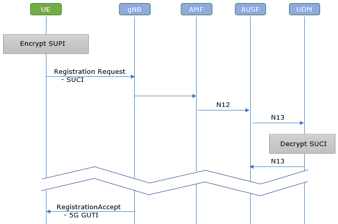
Table of Contents
Introduction
Elliptic Curve Cryptography (ECC) is a cornerstone of modern cryptographic security, renowned for providing strong encryption with relatively small key sizes, thus enabling efficient and secure communications over constrained channels. In the context of 5G mobile networks, ECC plays a vital role in safeguarding the privacy and security of user identities during network registration and authentication procedures. The Subscription Permanent Identifier (SUPI), which uniquely identifies a subscriber, must be protected from interception and unauthorized disclosure as it traverses the air interface. To this end, the SUPI is concealed using the Subscription Concealed Identifier (SUCI), a process underpinned by ECC-based encryption algorithms. This transformation ensures that sensitive user information is never transmitted in plaintext, mitigating risks such as identity theft and unauthorized tracking. The encryption and decryption mechanisms, based on standardized protocols like ECIES (Elliptic Curve Integrated Encryption Scheme), are implemented at both the User Equipment (UE) and the core network's Unified Data Management (UDM) entity. This architecture not only strengthens the security posture of next-generation mobile networks but also meets stringent regulatory and privacy requirements. By leveraging ECC, 5G systems achieve a robust balance between performance, scalability, and security, making the technology indispensable in the evolving telecommunications landscape.
-
Context of Elliptic Curve Cryptography (ECC) in 5G Networks
- ECC is integral to protecting subscriber identities by enabling secure SUPI-to-SUCI conversion.
- Used during critical signaling exchanges, such as network registration (e.g., RegistrationRequest, IdentityResponse), to ensure confidentiality over the air interface.
- Adopts industry-standard cryptographic protocols, ensuring interoperability and compliance with 3GPP specifications (notably TS 33.501).
-
Relevance and Importance of This Tutorial
- Addresses the industry's need to protect sensitive subscriber data in transit, aligning with privacy and security best practices.
- Guides practitioners through the configuration and testing of ECC-based SUPI/SUCI mechanisms in simulated or real 5G environments.
- Enhances understanding of the cryptographic processes that underpin modern mobile network security.
-
Learning Outcomes
- Gain practical knowledge of how to configure ECC for SUPI/SUCI encryption and decryption.
- Understand the end-to-end signaling flow for secure UE identity exchange in 5G networks.
- Acquire insights into the architectural role of ECC within the broader 5G security framework.
-
Prerequisites
- Familiarity with mobile network architecture (e.g., concepts such as UE, core network, UDM).
- Basic understanding of cryptographic principles and public key infrastructure.
- Awareness of 3GPP standards, especially those pertaining to security and identity management.
Summary of the Tutorial
This tutorial describes the procedure for testing the ECIES scheme profile A in a 5G standalone (SA) environment using Amarisoft Callbox and UEsim. The focus is on configuring the network and user equipment (UE) for ECIES authentication, performing the test, and validating the process through log analysis.
-
Test Setup:
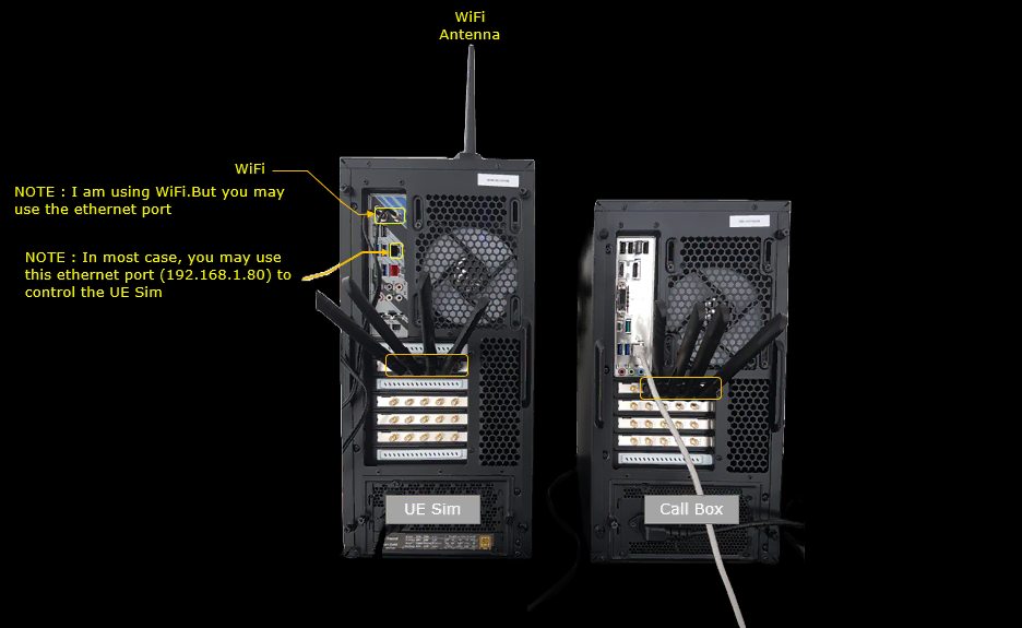
- The test setup consists of a Callbox acting as the gNB and core network, and a UEsim representing the UE. The physical and logical connections are illustrated in the referenced diagram.
-
Key Configuration Parameters:
-
eNB/gNB configuration:
- Set ecc_params with multiple pairs of home_nw_private_key and home_nw_key_id for parameters “A” and “B”. Additional pairs can be added as needed for the test.
-
UE configuration:
- Set ecc_params including scheme, home_nw_public_key, home_nw_public_key_id, and routing_indicator. Ensure the public key information matches one of the private keys configured in the network.
-
eNB/gNB configuration:
-
Test 1: ECIES Scheme Profile A
-
Configuration:
- Network Side (gNB/MME): Use a modified configuration file (mme-ims-ecc.cfg), derived from the default, with only relevant changes for ECC parameters.
- UE Side: Use a corresponding configuration file (ue-nr-sa-ecc.cfg), specifying the required public key and identifier.
- Ensure the key pairs between network and UE match for proper authentication.
-
Test Procedure:
- Verify the cell is configured as intended on the Callbox/gNB.
- Power on the UE using UEsim.
- Observe the UE performing attach procedures.
- Check and confirm that the UE successfully completes the attach and throughput is as expected.
-
Log Analysis:
- Confirm that the UE includes proper ECC parameters in the SUCI Information Element (IE) during the Registration Request.
- Verify that ECC information is transferred from the RAN to the core network via N12 interface.
- Ensure the AUSF (Authentication Server Function) verifies the ECC information with the UDM (User Data Management) over the N13 interface.
- Upon successful key verification, AUSF issues a status response allowing the AMF (Access Management Function) to trigger authentication.
-
Configuration:
This tutorial demonstrates the step-by-step configuration and validation for ECIES-based SUCI protection in a 5G SA scenario, focusing on key matching and proper signaling flow between UE and the core network.
Test Setup
Test setup for this tutorial is as shown below.
The Callbox runs the gNB and the core network, and the UE Sim runs the UE side. One RF cable connects the two, so a single SDR port carries the whole SA cell.
In this setup I control the UE Sim over WiFi. The ethernet port at 192.168.1.80 does the same job if you prefer a wired connection.
Key Configuration Parameters
Followings are important configuration parameters for this tutorial. You may click on the items for the descriptions from Amarisoft documents.
- enb configuration
- ue configuration
Test 1 : ECIES scheme profile A
This test is to test ECIES scheme profile A
Configuration
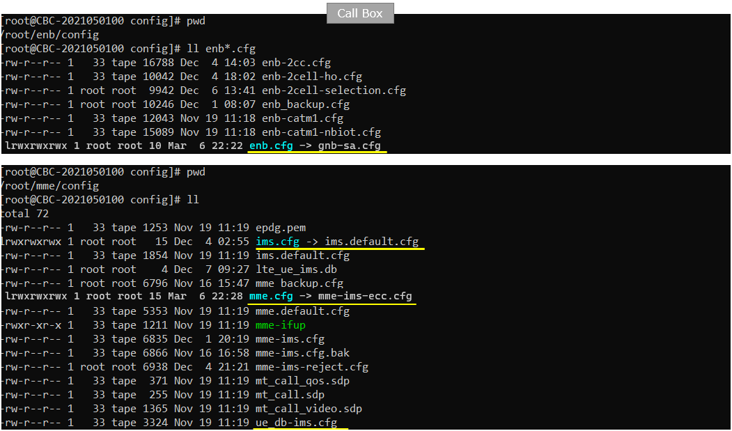
I used the mme-ims-ecc.cfg on gNB which is copied and modified from mme-ims.cfg (NOTE : only mme.cfg is changed for this tutorial and all other configurations are default files)
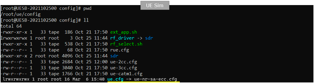
I used the ue-nr-sa-ecc.cfg on gNB which is copied and modified from ue-nr-sa.cfg
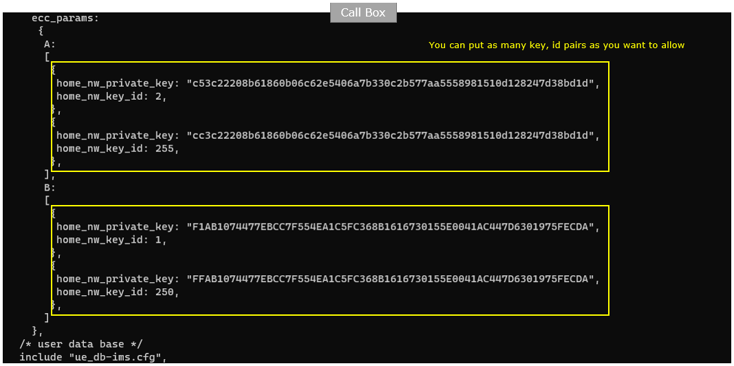
The mme configuration mme-ims-ecc.cfg is configured as follows. You just put pairs of home_nw_private_key and home_nw_key_id for the parameter A and B. You can put as many key, id pairs as you want to allow. (
Profile A carries two entries in this file. The first uses home_nw_key_id 2 and the second uses home_nw_key_id 255. Profile B also carries two entries, with home_nw_key_id 1 and home_nw_key_id 250. Each entry is one private key plus the identifier that belongs to it.
The identifier is what makes the pair work. The UE sends the home network public key identifier inside the SUCI. The callbox then looks up the private key holding the same home_nw_key_id and uses it to de-conceal the SUCI. A key id is an integer from 0 to 255. If you leave it out, the default is 1 for profile A and 2 for profile B.
Test 1 uses profile A only, so the two entries under B are not exercised. They stay in the file so that the same configuration can also serve a profile B test.
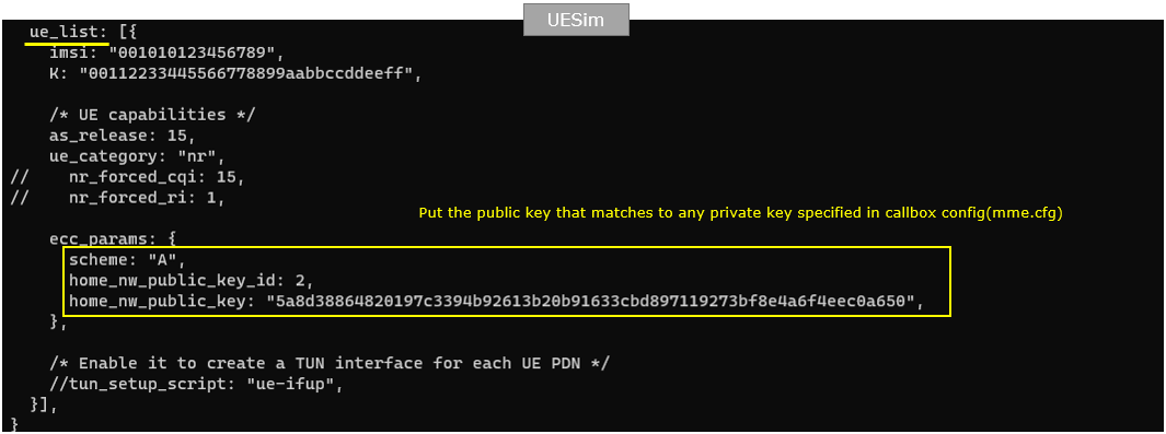
In ue-nr-sa-ecc.cfg , the configuration is done as follows. You need to specify any public key information (home_nw_public_key_id and home_nw_public_key) that matches any of the private key specified in the callbox. (
The UE in this file uses imsi 001010123456789, as_release 15 and ue_category nr. Its ecc_params block sets scheme to A, home_nw_public_key_id to 2, and home_nw_public_key to the value starting 5a8d3886.
The key id 2 is the part to check. It is the same id as the first profile A entry in mme-ims-ecc.cfg. The callbox can therefore find the matching private key when the SUCI arrives.
scheme accepts null, A or B. The public key length follows the scheme: 32 bytes for profile A and 33 bytes for profile B. home_nw_public_key_id runs from 0 to 255, and the value 0 is only valid for the null scheme. routing_indicator is not set here, so it keeps its default of "0".
Perform the Test
Check if the cell is configured as intended.
cell phy prints the physical layer settings. The gNB uses PLMN 00101 and gNB_ID 0x12345. Cell 0x001 runs NR band n78 with 20 MHz bandwidth. DL and UL ARFCN are both 632628 and the SSB ARFCN is 632544. Subcarrier spacing is 30 kHz, the modulation reaches 256QAM in both directions, and one antenna is used each way.
cell prints the cell level settings. TAC is 0x000064, pci is 500 and prach_seq is 1. dl_gain is 0.0 dB and the uplink is not disabled.
Nothing here is specific to ECC. I run these two commands only to confirm the cell came up as expected before powering the UE on.

Power on UE on UE sim.
power_on starts the UE on the UE Sim. The line above it sets file.path to /var/log/lte/ and file.rotate to 250M.
It is worth setting the log path before the run. The SUCI in the Registration request and the N12 and N13 exchanges are what you go back and read afterwards.

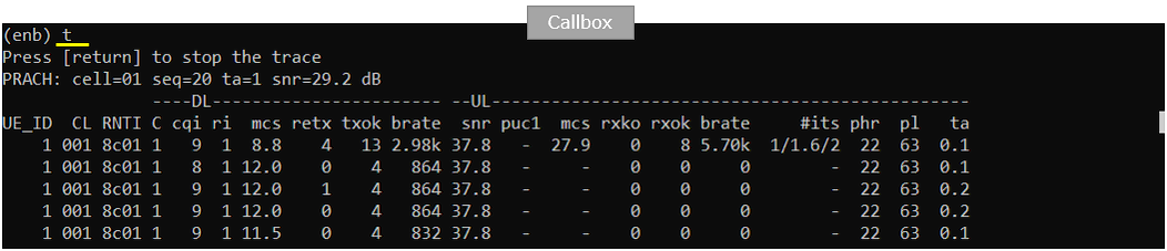
Confirm that the UE completes the attach and check the throughput.
t starts the trace on the callbox. The PRACH line reports cell=01 with seq=20, ta=1 and snr=29.2 dB, so the UE reached the cell on the first attempt.
The rows below show UE_ID 1 on cell 001 with RNTI 8c01. DL cqi is 9 and ri is 1, and DL mcs moves between 8.8 and 12.0. The first row carries a DL brate of 2.98k and a UL brate of 5.70k, and the later rows settle at 864 on the downlink. DL snr stays at 37.8 dB, phr is 22 and ta is around 0.1.
The rates are small because no user traffic is running. These rows still confirm the attach went through. The UE holds an RNTI on the cell and is being scheduled.
Log Analysis
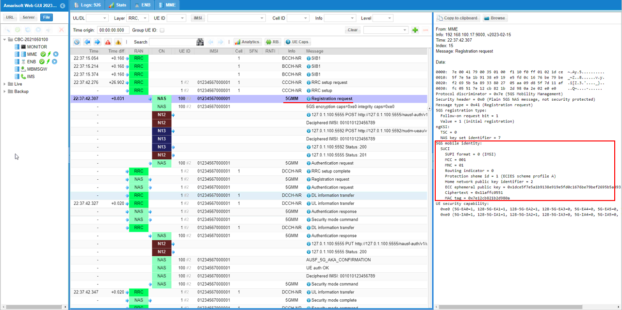
First when using ECC, UE is supposed to configure the proper ECC parameters in SUCI IE if Registration Request.
The Registration request arrives at 22:37:42.307 on 5GMM. Security header is 0x0, so this message is plain NAS and is not security protected. That is exactly why the identity has to be concealed before it goes out.
Inside the 5GS mobile identity the UE sends a SUCI rather than a SUPI. SUPI format is 0 for IMSI, MCC is 001 and MNC is 01. Routing indicator is 0. Protection scheme id is 1, which is ECIES scheme profile A. Home network public key identifier is 2, the same id set in ue-nr-sa-ecc.cfg.
The concealed part follows in three fields. ECC ephemeral public key starts 0x1dce5f7e, Ciphertext is 0x11affc0551, and MAC tag is 0x7e12cb821b2d980a. The home network needs the ephemeral public key to derive the same shared secret. The MAC tag lets it check that the ciphertext was not altered.
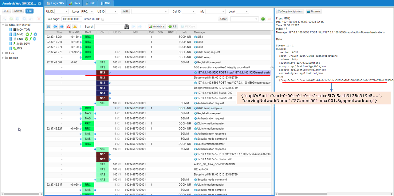
The ECC information (included in SUCI) is transferred to core network via N12 interface (the interface between AMF and AUSF).
The N12 row is an HTTP POST to /nausf-auth/v1/ue-authentications on 127.0.1.1:5555, which is the AUSF. The body is JSON and carries two fields. supiOrSuci holds the SUCI, and servingNetworkName is 5G:mnc001.mcc001.3gppnetwork.org.
The SUCI is the same information that arrived over NAS, written in text form as suci-0-001-01-0-1-2 followed by the scheme output. The leading 0 is the SUPI type. Then come MCC 001 and MNC 01, routing indicator 0, protection scheme 1 and home network public key id 2. The scheme output after that starts 1dce5f7e, the ephemeral public key from the Registration request.
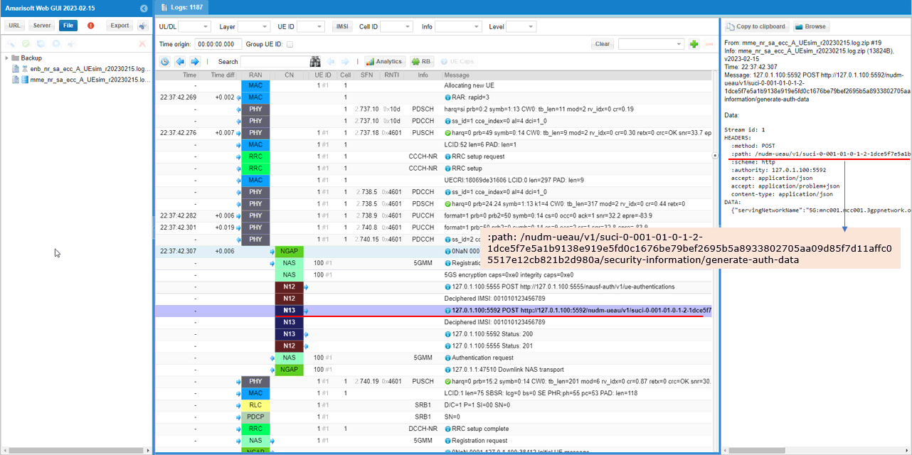
The AUSF verifies the information with UDM over N13 interface (the interface between AUSF and UDM).
The N13 row is an HTTP POST to 127.0.1.1:5592, which is the UDM. This time the SUCI travels in the request path instead of the body. The path is /nudm-ueau/v1/suci-0-001-01-0-1-2-1dce...980a/security-information/generate-auth-data.
That path ends with the ephemeral public key, the ciphertext 11affc0551 and the MAC tag 7e12cb821b2d980a. The UDM therefore receives everything it needs to de-conceal the identity. The body only carries servingNetworkName.
The home network private key configured in mme-ims-ecc.cfg belongs to the UDM. De-concealment happens there, not in the AUSF, which is why the AUSF has to forward the SUCI over N13 at all.
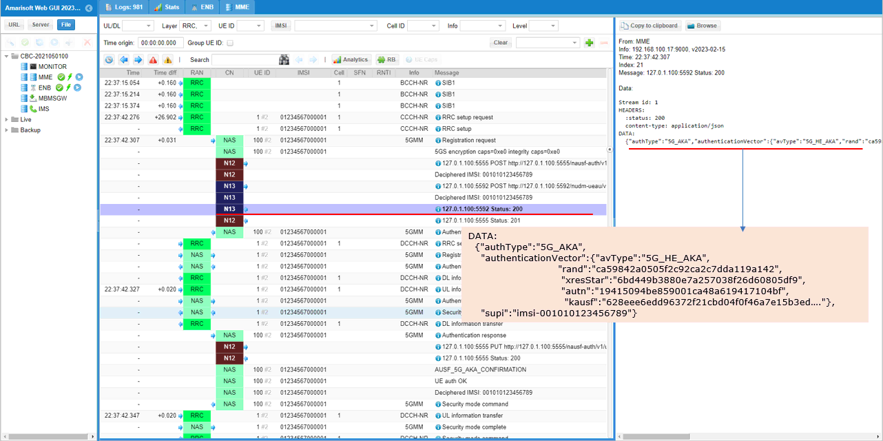
If the key is verified successfully, AUSF issues Status 200 with corresponding authentication key so that AMF trigger Authentication Request.
The Status 200 row is the response on 127.0.1.1:5592. Its body carries authType 5G_AKA and an authenticationVector of avType 5G_HE_AKA. The vector holds rand ca59842a0505f2c92ca2c7dda119a142, xresStar 6bd449b3880e7a257038f26d60805df9, autn 19415094be859001ca48a619417104bf, and kausf starting 628eee6e.
The field to look at for ECC is supi. It reads imsi-001010123456789 in plain text. This is the de-concealed identity, and it is the proof that the private key on the callbox matched the public key on the UE. If the two had not matched, no SUPI would come back here.
A Status 201 on 127.0.1.1:5555 follows, and the Authentication request then goes out to the UE over NAS. From that point the run is ordinary 5G AKA.
RRC / NAS Signaling
This section lists the NAS message that carries the concealed identity, decoded field by field. The SUCI fields are the ones to compare against your own trace when you check an ECC configuration.
RegistraionRequest (SA)
: This is the RegistrationRequest sent by UE that should be decoded by Network (
Protocol discriminator = 0x7e (5GS Mobility Management)
Security header = 0x0 (Plain 5GS NAS message, not security protected)
Message type = 0x41 (Registration request)
5GS registration type:
Follow-on request bit = 1
Value = 1 (initial registration)
ngKSI:
TSC = 0
NAS key set identifier = 7
5GS mobile identity:
SUCI
SUPI format = 0 (IMSI)
MCC = 001
MNC = 01
Routing indicator = 0
Protection sheme id = 1 (ECIES scheme profile A)
Home network public key identifier = 2
ECC ephemeral public key = 0x1dce5f7e5a1b9138e919e5fd0c1676be79bef2695b5a8933802705aa09d85f7d
Ciphertext = 0x11affc0551
MAC tag = 0x7e12cb821b2d980a
UE security capability:
0xe0 (5G-EA0=1, 128-5G-EA1=1, 128-5G-EA2=1, 128-5G-EA3=0, 5G-EA4=0, 5G-EA5=0, 5G-EA6=0, 5G-EA7=0)
0xe0 (5G-IA0=1, 128-5G-IA1=1, 128-5G-IA2=1, 128-5G-IA3=0, 5G-IA4=0, 5G-IA5=0, 5G-IA6=0, 5G-IA7=0)