NR SA FDD Asymetric Channel Bandwidth
The purpose of this tutorial is to show you how to set different channel bandwidth for downlink and uplink in NR SA. It is assumed that you don't have any previous experience with Amari callbox.
Asymetric Channel Bandwidth in this tutorial indicates the case where Bandwidth for DL and UL are different. In most cases, it is assumed that the bandwidth of DL and UL is same in most of the default configuration. I think we can think of two ways to configure DL bandwidth and UL bandwidth differently as listed below.
- Setting the number of RBs differently for DL and UL within initial BWP
- Setting a BWP (non-initial BWP) with different bandwidth for DL and UL and switch to the BWP
The first method is used in this tutorial.
Table of Contents
- NR SA FDD Asymetric Channel Bandwidth
Introduction
In 5G New Radio (NR) Standalone (SA) deployments, the flexibility to configure radio resources is a defining feature that enables operators to optimize network performance for diverse use cases. One such configurable aspect is the channel bandwidth allocation for downlink (DL) and uplink (UL), which can be independently set to accommodate asymmetric traffic demands. Traditionally, NR systems assume symmetric bandwidth allocation, where both DL and UL operate over identical bandwidths, simplifying network planning and resource management. However, real-world scenarios often necessitate differing bandwidths due to varying uplink and downlink traffic profiles—such as in applications with heavy downlink streaming and minimal uplink data. Architecturally, NR introduces the concept of Bandwidth Parts (BWPs), which allow for granular control over the bandwidth assigned to a User Equipment (UE) for both DL and UL. By configuring the number of Resource Blocks (RBs) within a BWP, operators can tailor the channel bandwidth for each link direction. This capability is particularly significant in the context of 5G’s flexible numerology and spectrum utilization, positioning asymmetric configurations as a powerful tool for optimizing spectrum efficiency. Within the broader 5G ecosystem, such flexibility supports diverse service requirements, enhances user experience, and enables efficient network slicing. The Amari Callbox, a versatile 5G test platform, provides the infrastructure necessary to experiment with and validate these advanced configurations in a controlled environment.
-
Context and Background
- 5G NR SA supports flexible radio resource management, including independent configuration of DL and UL channel bandwidths.
- Bandwidth Parts (BWPs) enable separation and dynamic allocation of resources, allowing for asymmetric bandwidth assignment tailored to application needs.
- Amari Callbox is a widely used 5G test solution that facilitates practical experimentation with NR features such as asymmetric channel bandwidth.
-
Relevance and Importance
- Asymmetric bandwidth allocation is crucial for optimizing spectral efficiency in scenarios with uneven uplink and downlink traffic demands.
- Understanding how to configure these parameters is essential for network engineers, testers, and researchers working with emerging 5G use cases and deployments.
- The tutorial addresses a common limitation in default configurations and demonstrates how to overcome it using a real-world test platform.
-
Tutorial Objectives
- Provide step-by-step guidance on setting different channel bandwidths for DL and UL in a 5G NR SA environment using Amari Callbox.
- Explain the underlying technical concepts—such as BWPs and RB allocation—that enable asymmetric channel bandwidth.
- Demonstrate practical configuration using the first method: setting the number of RBs differently for DL and UL within the initial BWP.
-
Expected Learning Outcomes
- Gain a foundational understanding of bandwidth configuration in 5G NR SA.
- Acquire hands-on experience with Amari Callbox for radio resource management tasks.
- Develop the ability to implement and validate asymmetric channel bandwidth configurations.
-
Prerequisite Knowledge or Skills
- Basic familiarity with 5G NR concepts and terminology (recommended but not required).
- No prior experience with Amari Callbox is assumed; the tutorial is designed for beginners.
- General understanding of wireless communication principles is helpful for contextualizing the concepts covered.
Summary of the Tutorial
This tutorial demonstrates the procedure to test an NR Standalone (SA) asymmetric channel bandwidth configuration using a UE simulator and callbox setup.
-
Test Setup:
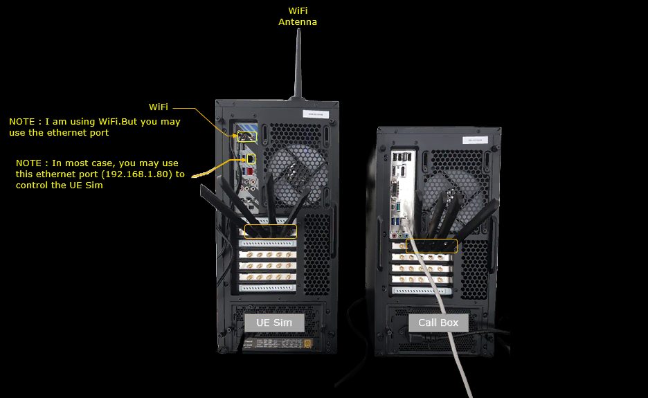
- The test environment involves a callbox and a UE simulator (UEsim) connected as shown in the referenced diagram.
-
Key Configuration Parameters:
- n_rb_dl: Number of downlink resource blocks.
- n_rb_ul: Number of uplink resource blocks.
-
Configuration Procedure:
- Proper alignment of configuration between UE simulator and callbox is critical.
- Default configuration files (ue.default.cfg, enb.default.cfg) are used unless otherwise noted.
- For this test, ue-sa-fdd-asym.cfg and gnb-sa-fdd-asym.cfg are utilized. These are derived from their respective default standalone configuration files.
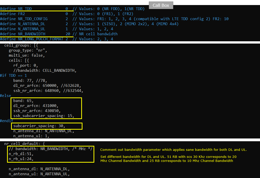
- gnb-sa-fdd-asym.cfg (callbox): Configured with asymmetric bandwidth — n_rb_dl (DL) set for 20 MHz channel bandwidth and n_rb_ul (UL) set for 10 MHz. NR_TDD is set to 0 for FDD operation.
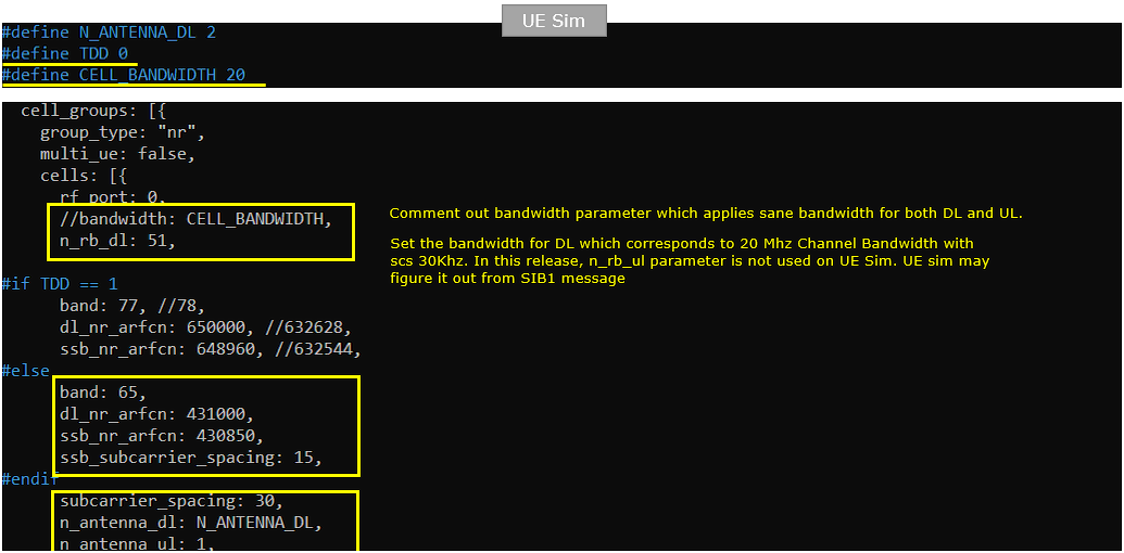
- ue-sa-fdd-asym.cfg (UEsim): Only n_rb_dl is configured; UL bandwidth is obtained from SIB1 decoding. Bandwidth parameter is commented out to allow for asymmetric DL/UL. NR_TDD is set to 0 for FDD operation.
-
Test Execution Procedure:
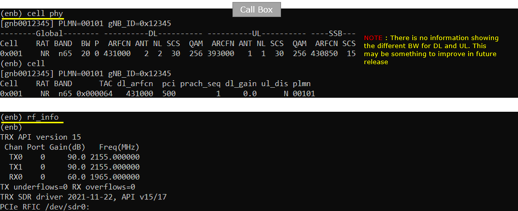
- Verify cell configuration using the cell phy command on the callbox; confirm intended setup.
- Use the cells command to check if the UE simulator detects the cell. Once detected, power on the UE.
- Use the t command to verify that the UE connects to the cell and completes the attach procedure.
- Test data path connectivity by pinging the UE from the callbox. Successful ping replies confirm that both uplink and downlink communications are functional with the asymmetrical bandwidth configuration.
-
Log Analysis:
- Inspect logs to verify DL and UL bandwidths as indicated in the SIB1 message.
- Confirm the bandwidth values of both downlink and uplink via locationBandwidth in the initialDownlinkBWP and initialUplinkBWP sections of SIB1.
- Use external tools (e.g., RIV calculator) for interpreting resource block assignments.
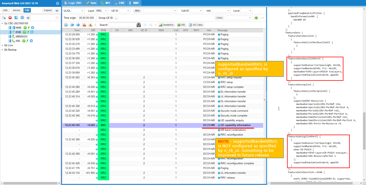
- Check UE capability information to ensure support for configured bandwidths (via featureSetDownlinkPerCC and featureSetUplinkPerCC).
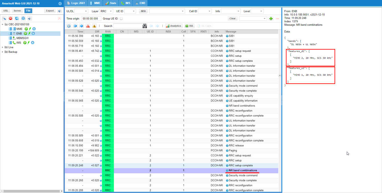
- Amarisoft internal logs can also confirm the NR band combination and resource block allocations.
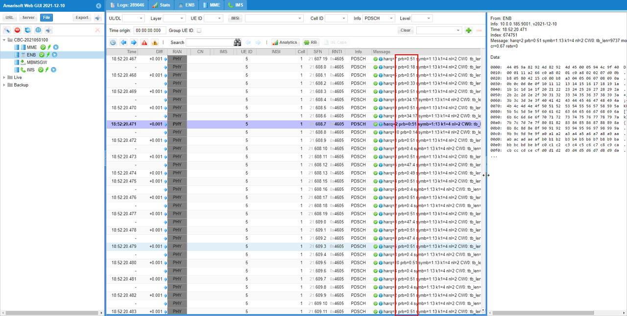
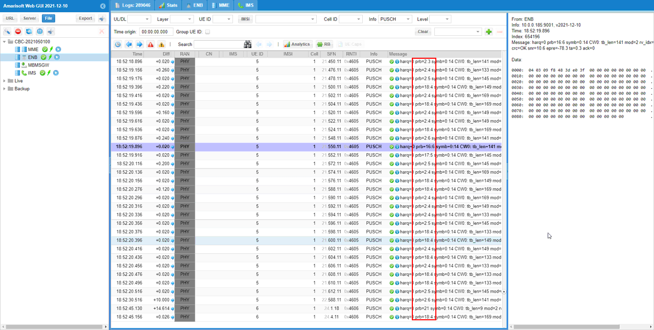
- It is observed that the maximum Physical Resource Block (PRB) does not exceed the configured limits for both PDSCH (DL) and PUSCH (UL), matching the asymmetric configuration.
The overall methodology validates the ability of the UE and gNB (callbox) to establish, configure, and maintain asymmetric bandwidth operation in NR SA FDD mode, confirming both configuration and functional connectivity through stepwise verification and log analysis.
Test Setup
Test setup for this tutorial is as shown below.
Key Configuration Parameters
Followings are important configuration parameters for this tutorial. You may click on the items for the descriptions from Amarisoft documents.
Configuration
An important thing in using UE sim is to do proper matching between UE sim configuration and Call box configuration In this tutorial, I used the ue.default.cfg and and enb.default.cfg without any change
If you use other Network (e.g, other network simulator or real network), you have to make it sure to configure UE sim according to the settings on network side
I used ue-sa-fdd-asym.cfg which is copied from ue-nr-sa.cfg.

I used gnb-sa-fdd-asym.cfg which is copied from gnb-sa.cfg.

The configuration in gnb-sa-fdd-asym.cfg (Callbox) is set as follows. The keypoint is that the nuber of RB for n_rb_dl and n_rb_ul are set to be different. NR_TDD is set to 0 since this is for FDD test. The important point in this configuration is that n_rb_dl and n_rb_ul are set differently. n_rb_dl (Downlink bandwidth) is set to the channel bandwidth of 20 Mhz and n_rb_ul (Uplink bandwidth) is set to the channel bandwidth of 10 Mhz
The configuration in ue-sa-fdd-asym.cfg (Callbox) is set as follows. In this configuration, you would notice that only n_rb_dl is configured. UL bandwidth will be detected from SIB1 decoding. NR_TDD is set to 0 since this is for FDD test. In this configuration, bandwidth parameter is commented out since the different bandwidth will be used for DL and UL. Only dl bandwidth is configured with n_rb_dl for UEsim to detect the cell and decode SIBs. UL bandwidth will be informed to UE by SIB1.
Perform the Test
Check out cell configuration with cell phy command and see if the cell is configured as intended. NOTE that there is no information showing the different BW for DL and UL.
If the cell is properly configured. Check if the cell can be detected by UEsim. You can check the cell detection status with cells command. Once cell is properly detected, power on UE.
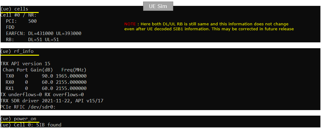
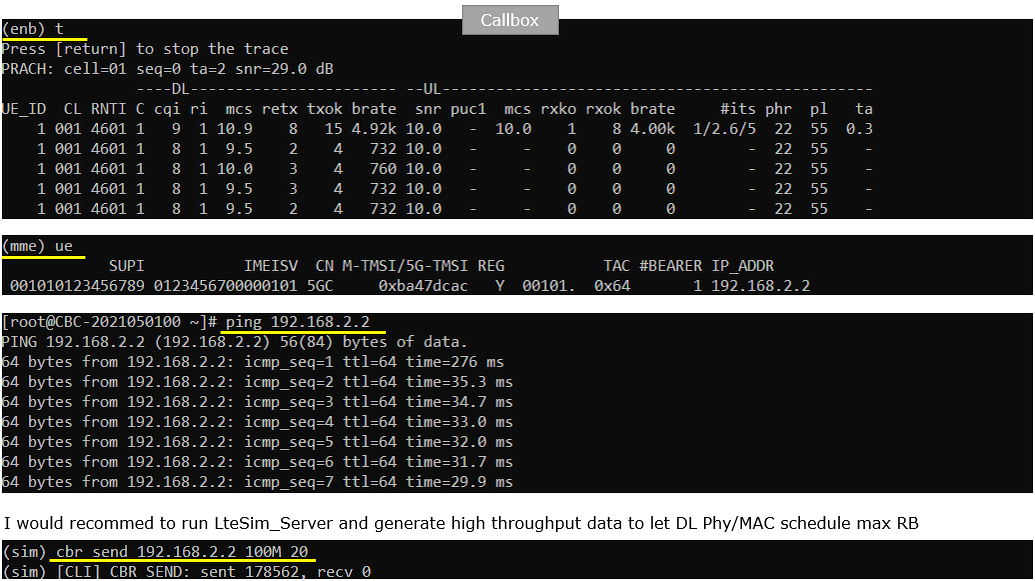
Now check if UE gets connected to the cell properly. You can do this with t command. If UE properly completes the attach, check if the IP data can go through both uplink and downlink. The simplest way to do this is to ping the UE. If you get the ping reply, it indicates both DL and UL connection is properly established with asymatric bandwidth configured in this test.
Log Analysis
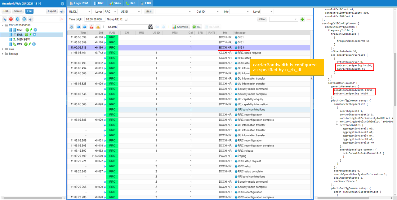
You can confirm on DL and UL bandwidth in SIB1 message.
Confirm DL Bandwidth in locationBandwidth in initialDownlinkBWP. The start RB and bandwidth is configured as RIV in RRC. If you want to convert this RIV to start RB and NRB, use this calculator.
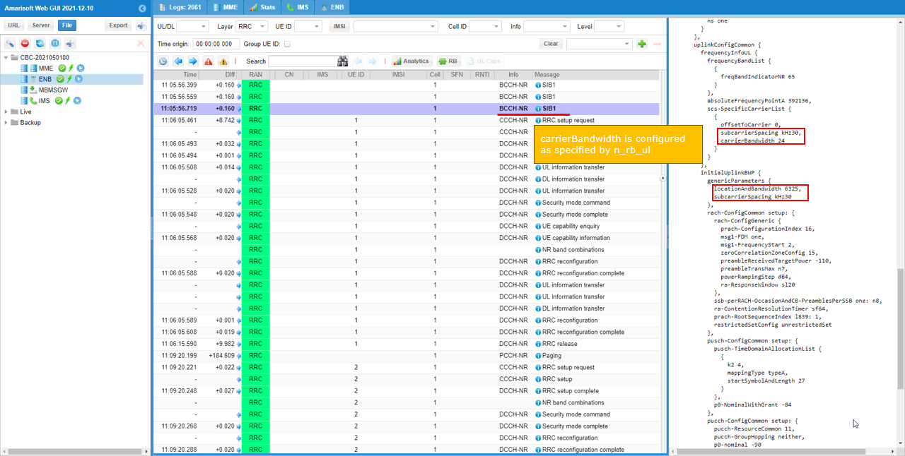
Confirm DL Bandwidth in locationBandwidth in initialUplinkBWP. The start RB and bandwidth is configured as RIV in RRC. If you want to convert this RIV to start RB and NRB, use this calculator.
check if your UE (DUT) support the bandwidth that you configured. You can check it out via featureSetDownlinkPerCC and featureSetUplinkPerCC in UE Capability Information message from the UE.
The same information can be confirmed by Amarisoft Internal log NR band combination.
You would notice that the max PRB does not go over 51st RB for PDSCH (Downlink transmission)
You would notice that the max PRB does not go over 24th RB for PUSCH (Uplink transmission)
RRC / NAS Signaling
SIB1 (SA)
: This is the SIB1 message sent by gNB to configure NR SA. (
{
message c1: systemInformationBlockType1: {
...
servingCellConfigCommon {
downlinkConfigCommon {
frequencyInfoDL {
frequencyBandList {
{
freqBandIndicatorNR 78
}
},
...
},
initialDownlinkBWP {
genericParameters {
locationAndBandwidth 13750,
subcarrierSpacing kHz30
},
offsetToPointA 36,
scs-SpecificCarrierList {
{
offsetToCarrier 0,
subcarrierSpacing kHz30,
carrierBandwidth 51
}
}
},
uplinkConfigCommon {
frequencyInfoUL {
scs-SpecificCarrierList {
{
offsetToCarrier 0,
subcarrierSpacing kHz30,
carrierBandwidth 24
}
},
p-Max 10
},
initialUplinkBWP {
genericParameters {
locationAndBandwidth 6325,
subcarrierSpacing kHz30
},
}