
NR SA 2Step RACH
The purpose of this tutorial is to show you how to test 2Step RACH. Since I don't have any commercial UE supporting 2 step RACH I used Amari UEsim as DUT. I will put the test with commercial UE when I have any commercial UE supporting the feature. The regular RACH that is commonly used is 4 step RACH. Obviously 2 step RACH takes less steps to complete. It would shorten the signaling time greatly and I can even shorten the required timing for PUSCH transmission since PUSCH can be transmitted at the first step (Step 1) of the process. Overall process and Configuration of 2 Step RACH is as follows.
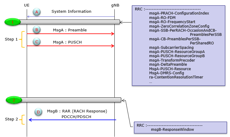
Image Source : Sharetechnote
Table of Contents
Introduction
The 2-Step Random Access Channel (RACH) procedure represents a significant advancement in 5G NR (New Radio) access technologies, designed to enhance the efficiency and responsiveness of initial access mechanisms within cellular networks. Traditional 4-Step RACH, a well-established process in LTE and early 5G deployments, involves a sequence of message exchanges between User Equipment (UE) and the gNodeB (gNB) to establish uplink synchronization and initiate communication. The 2-Step RACH procedure, introduced in 3GPP Release 16 and supported by advanced simulation platforms like Amari UEsim, streamlines this process by consolidating signaling steps. This reduction in procedural overhead allows the UE to transmit both the preamble and initial uplink data in a single step, thereby decreasing access latency and improving resource utilization. Architecturally, the 2-Step RACH integrates tightly with the 5G NR physical layer, leveraging enhancements in PUSCH (Physical Uplink Shared Channel) transmission and RACH configuration parameters. Its adoption is particularly critical for latency-sensitive applications such as massive IoT deployments, URLLC (Ultra-Reliable Low Latency Communications), and scenarios requiring rapid network access. By shortening the signaling exchange, the 2-Step RACH procedure not only optimizes network responsiveness but also contributes to improved user experience and overall system capacity in dense network environments.
-
Context and Background
- The Random Access Channel (RACH) is a fundamental component of cellular network procedures, supporting initial access, handover, and uplink synchronization between the UE and gNB.
- While the conventional 4-Step RACH has been the industry standard, the evolution to 2-Step RACH addresses emerging requirements in 5G NR for lower latency and improved spectral efficiency.
- The 2-Step RACH relies on enhancements in 5G NR’s physical and MAC layers, utilizing advanced scheduling and resource allocation strategies.
-
Relevance and Importance of the Tutorial Topic
- Understanding and testing 2-Step RACH is essential for network engineers, researchers, and developers working with 5G NR, especially in contexts where rapid access and reduced signaling overhead are critical.
- This tutorial provides practical insights by demonstrating the procedure using Amari UEsim, a widely used UE simulator, making the concepts accessible even in the absence of commercial UEs supporting this feature.
- The knowledge gained is directly applicable to real-world scenarios, including network optimization, performance analysis, and deployment of latency-sensitive 5G services.
-
What Learners Will Gain
- A comprehensive understanding of the architectural differences between 2-Step and 4-Step RACH procedures.
- Practical experience in configuring and testing 2-Step RACH using simulation tools.
- Insights into the performance benefits and implementation considerations of 2-Step RACH in 5G NR networks.
- Awareness of the feature’s deployment status and compatibility considerations in commercial networks.
-
Prerequisite Knowledge or Skills
- Familiarity with 5G NR network architecture and terminology (e.g., gNB, UE, PUSCH, MAC/PHY layers).
- Basic understanding of radio access procedures and the role of RACH in cellular systems.
- Experience with network testing tools or simulators such as Amari UEsim is beneficial but not mandatory.
- Some exposure to 3GPP technical specifications, particularly those related to RACH and 5G NR, will enhance comprehension.
Summary of the Tutorial
The tutorial demonstrates the configuration and validation of the 2-step RACH (Random Access Channel) procedure in NR Standalone (SA) mode, using an FDD duplex mode and 2x2 UL MIMO. The test utilizes an Amarisoft Callbox and UEsim, with detailed steps for both configuration and execution.
-
Test Setup:
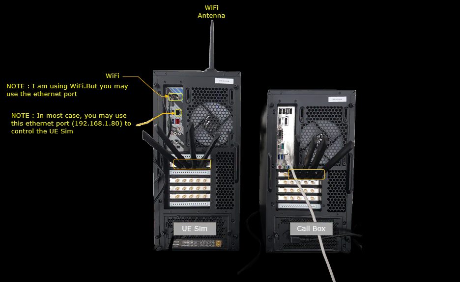
- The setup involves an Amarisoft Callbox and UEsim, connected as depicted in the provided diagram.
-
Key Configuration Parameters:
- Parameters such as two_steps_prach, shared_ro, msga_pusch (with sub-parameters like mcs, time_domain_offset, l_crb, po_fdm, rb_start, n_symb, dmrs_cdm_group, dmrs_n_ports), msga_rsrp_threshold, msgb_response_window, and msgb_mcs are highlighted as essential for 2-step RACH operation.
-
Test Procedure: 2 step RACH with FDD, UL MIMO 2x2
-
Configuration:
- Ensure matching configurations between UEsim and Callbox. The default configuration files (ue.default.cfg and enb.default.cfg) are used as a baseline without modification.
- For UEsim, use ue-nr-sa-2step-rach.cfg (copied from ue-nr-sa.cfg). For Callbox, use gnb-sa-2step-rach.cfg (from gnb-sa.cfg).
-
Callbox Configuration Highlights:
- Set NR_TDD to 0 (FDD mode), N_ANTENNA_DL and N_ANTENNA_UL to 2 (2x2 MIMO), and enable SRS by setting USE_SRS to 1.
- Configure desired FDD band and frequency, using band 7 (n7) in this test.
- In two_steps_prach, configure shared_ro, msgA, and msgB settings. For msga_pusch, set the relevant physical layer parameters for PUSCH.
- In srs_resource, set n_ports to match N_ANTENNA_UL for UL MIMO operation.
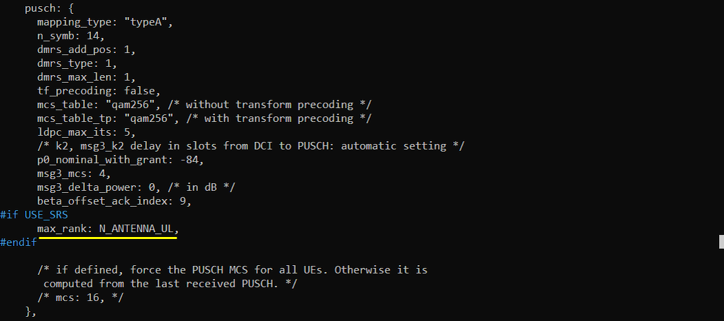
- Set max_rank in pusch configuration to match N_ANTENNA_UL for MIMO.
-
UEsim Configuration Highlights:
- Ensure N_ANTENNA_DL and N_ANTENNA_UL match the Callbox.
- Set TDD to 0 (FDD mode).
- Band and frequency settings (band, dl_nr_arfcn, subcarrier_pacing) should mirror the Callbox.
- Set rx_to_tx_latency to be less than time_domain_offset of two_step_prach in Callbox.
-
Test Execution:
- Verify cell configurations with cell phy and cell commands to ensure proper setup.
- Power on the UE using the power on command on UEsim (or turn on a commercial UE if used).
- Confirm initial attach and data flow using the 't' command. Specific 2-step RACH activity is verified via protocol logs.
-
Log Analysis:
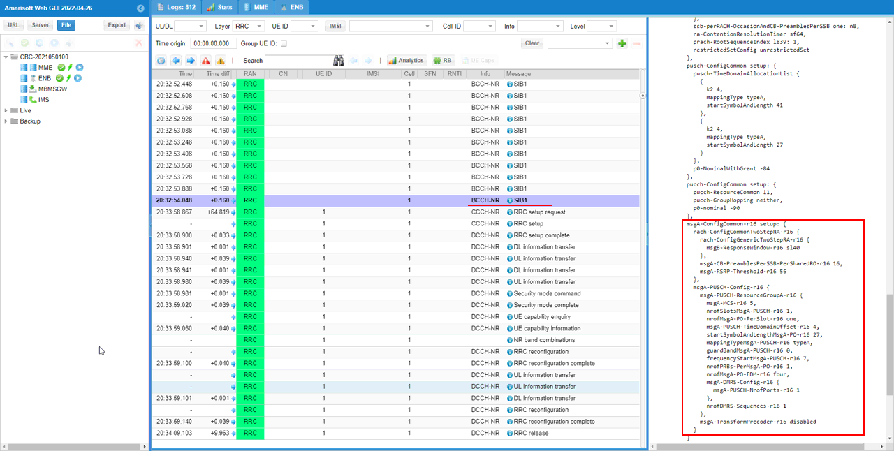
- Inspect SIB1 to verify RACH configuration via rach-ConfigCommon and pusch-ConfigCommon.
- Check msgA configuration in SIB1 for proper parameter settings.
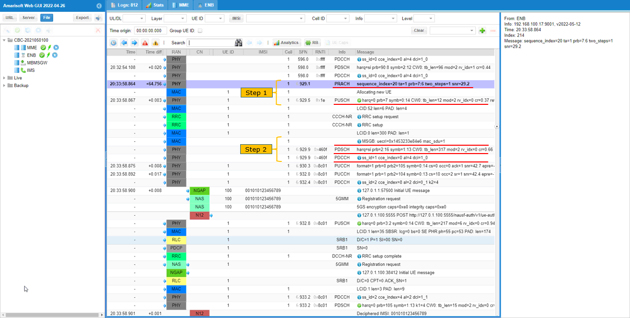
- Analyze low-layer logs to confirm correct 2-step RACH operation: look for PRACH and PUSCH (Step 1), followed by PDCCH/PDSCH (Step 2).
-
Configuration:
The tutorial provides clear, stepwise methodologies for configuring both network and UE simulators, executing the test, and validating the results through command-line and log analysis. Special attention is given to ensuring configuration consistency and the specific requirements for 2-step RACH in an NR SA environment with FDD and UL MIMO.
Test Setup
Setup A
Test setup for this tutorial is as shown below.
Key Configuration Parameters
Followings are important configuration parameters for this tutorial. You may click on the items for the descriptions from Amarisoft documents.
- two_steps_prach : In this link, you will get the descriptions for all the items listed below.
- shared_ro
- cb_preambles_per_ssb_per_sro
- msga_pusch
- mcs
- time_domain_offset
- l_crb
- po_fdm
- rb_start
- n_symb
- dmrs_cdm_group
- dmrs_n_ports
- msga_rsrp_threshold
- msgb_response_window
- msgb_mcs
Test 1 : 2 step RACH with FDD, UL MIMO 2x2
This is to show how to configure and validate the 2 step RACH in NR SA. The duplex mode configured in this test is FDD and MIMO scheme for UL is 2x2.
Configuration
An important thing in using UE sim is to do proper matching between UE sim configuration and Call box configuration In this tutorial, I used the ue.default.cfg and and enb.default.cfg without any change
If you use other Network (e.g, other network simulator or real network), you have to make it sure to configure UE sim according to the settings on network side
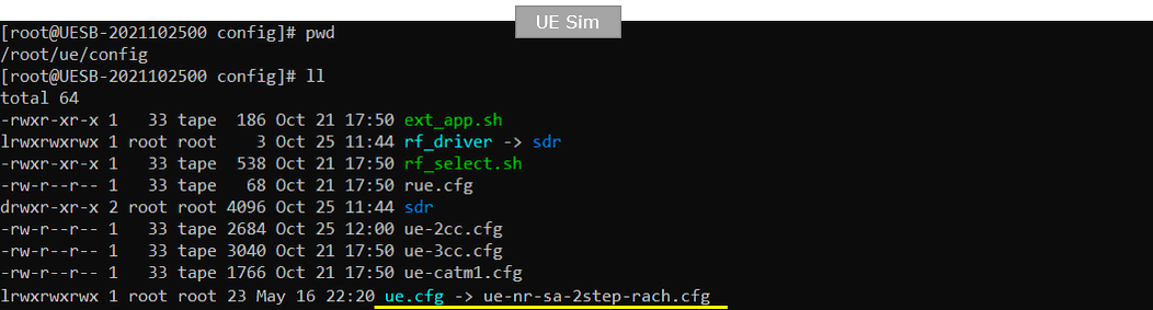
I used ue-nr-sa-2step-rach.cfg which is copied from ue-nr-sa.cfg.
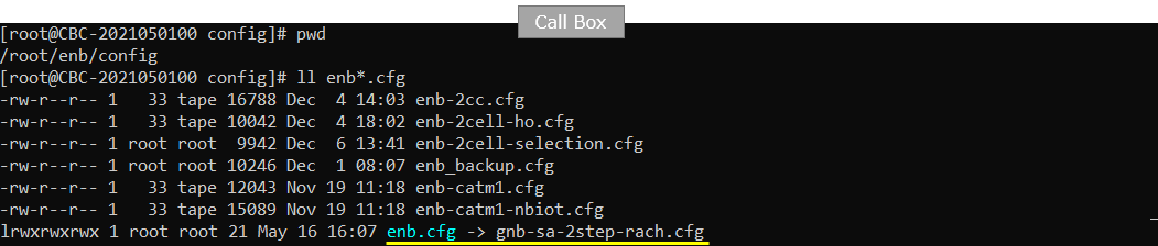
I used gnb-sa-2step-rach.cfg which is copied from gnb-sa.cfg.
Configuration for Callbox
The configuration in gnb-sa-2step-rach.cfg (Callbox) is set as follows.
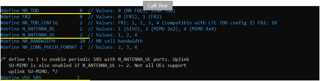
In this test, NR_TDD is set to 0 to select NR FDD operation. N_ANTENNA_DL and N_ANTENNA_UL are both set to 2, configuring two downlink and two uplink antenna ports for 2×2 MIMO operation. USE_SRS is set to 1 to enable periodic SRS transmission, allowing the gNB to estimate the uplink channel and support uplink SU-MIMO.
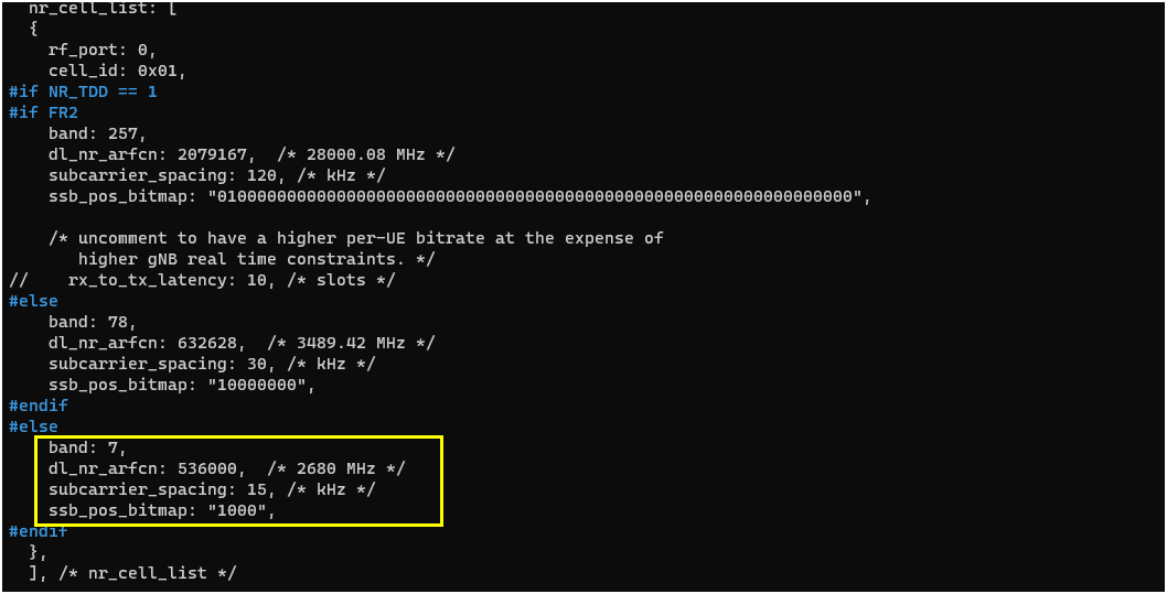
Configure the operating band and frequency according to the test environment. In this test, NR band n7 is selected with DL NR-ARFCN 536000, corresponding to 2680 MHz. The subcarrier spacing is set to 15 kHz, and ssb_pos_bitmap is configured as 1000 to define the active SSB position.
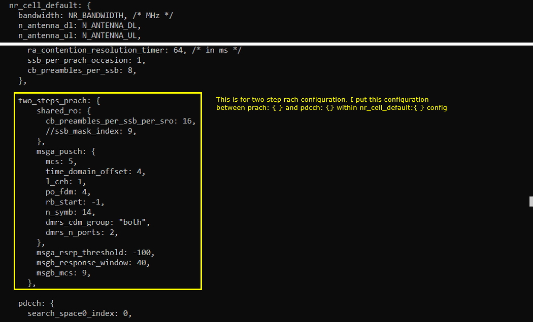
Configure the two_steps_prach section within nr_cell_default to define the resources and operating parameters for NR 2-Step RACH. The shared_ro section specifies how PRACH occasions and contention-based preambles are shared between conventional 4-Step RACH and 2-Step RACH. In this example, cb_preambles_per_ssb_per_sro is set to 16, allocating 16 contention-based preambles per SSB for each shared RACH occasion.
The msga_pusch section defines the physical-layer resources used for the PUSCH part of MsgA. The MCS is set to 5, while time_domain_offset and po_fdm determine the time and frequency placement of the MsgA PUSCH occasion relative to the associated PRACH transmission. The RB allocation starts from the configured resource position, uses one contention resource block group, and spans 14 OFDM symbols. dmrs_cdm_group is set to both and dmrs_n_ports is set to 2 so that MsgA PUSCH can use two DMRS ports for uplink MIMO reception.
The msga_rsrp_threshold parameter is set to -100 dBm and is used by the UE when determining whether the received signal level is suitable for attempting 2-Step RACH. After transmitting MsgA, the UE monitors for MsgB during the configured msgb_response_window of 40 ms. The gNB transmits MsgB using msgb_mcs 9. Together, these settings define the shared PRACH resources, the MsgA preamble and PUSCH transmission, and the MsgB response behavior.
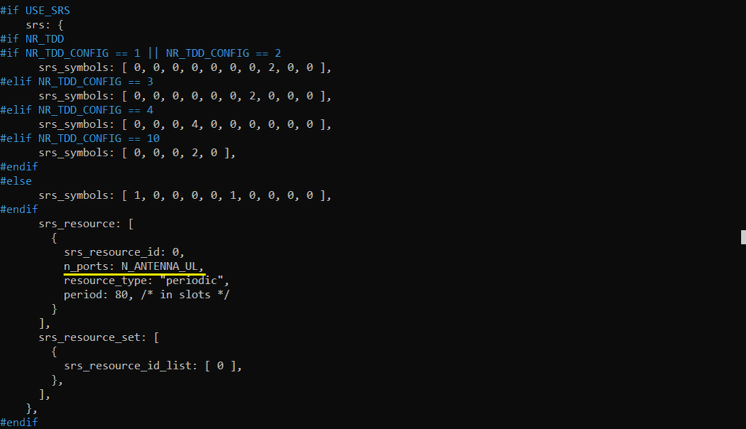
In the srs_resource configuration, n_ports is set to N_ANTENNA_UL so that the number of SRS antenna ports matches the configured uplink antenna ports. In this test, N_ANTENNA_UL is 2, so the UE transmits SRS using two ports to support uplink 2×2 MIMO channel estimation. The SRS resource is configured as periodic with an 80-slot period and is referenced by srs_resource_set.
In the PUSCH configuration, max_rank is set to N_ANTENNA_UL so that the maximum transmission rank matches the number of configured uplink antenna ports. Since N_ANTENNA_UL is set to 2 in this test, the gNB can schedule PUSCH transmission with a rank of up to 2, enabling uplink 2×2 MIMO when supported by the UE and radio conditions.
Configuration for UEsim
The configuration in ue-nr-sa-2step-rach.cfg (UEsim) is set as follows.
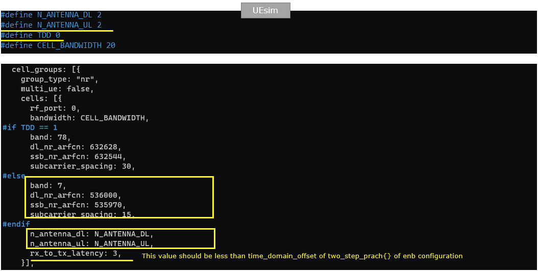
Configure the UEsim radio parameters to match the Callbox configuration. N_ANTENNA_DL and N_ANTENNA_UL are both set to 2 so that the simulated UE uses the same 2×2 downlink and uplink antenna configuration as the Callbox. TDD is set to 0 to select FDD operation, and the cell bandwidth is set to 20 MHz.
The operating band, DL NR-ARFCN, SSB NR-ARFCN, and subcarrier spacing must also match the serving cell configuration. In this test, band n7 is used with dl_nr_arfcn 536000, ssb_nr_arfcn 535970, and 15 kHz subcarrier spacing.
The rx_to_tx_latency parameter defines the UE processing delay between reception and the following uplink transmission. It is set to 3 slots, which must be smaller than the time_domain_offset configured for MsgA PUSCH in the Callbox. Since the Callbox uses time_domain_offset 4, the UE has enough time to process the PRACH timing and transmit the associated MsgA PUSCH at the configured occasion.
Perform the Test
Before starting the test, verify the active cell configuration using the cell phy and cell commands on the Callbox. The cell phy output confirms that the NR cell is operating in band n7 with 20 MHz bandwidth, DL NR-ARFCN 536000, two downlink and two uplink antenna ports, and 15 kHz subcarrier spacing. It also shows the UL NR-ARFCN 512000 and SSB NR-ARFCN 535970. The cell command confirms the same serving-cell configuration, including PCI 500, PRACH sequence index 1, and PLMN 00101. Check that these values match the intended Callbox and UEsim settings before proceeding with the 2-Step RACH test.

Once the cell configuration has been verified, start the simulated UE by entering the power_on command in the UEsim console. The startup information confirms that the UE is configured for band n7 with a 23.04 MHz sample rate, a downlink frequency of 2680.1 MHz, and two downlink and two uplink antenna ports. For a commercial UE, simply power on the device after confirming that its supported band and radio settings match the configured cell.

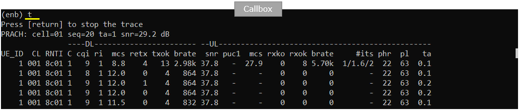
Confirm that the UE has completed the initial attachment and that physical-layer data is flowing by running the t command on the Callbox. The trace output shows an active UE context with an assigned C-RNTI and ongoing downlink and uplink traffic, confirming that the connection has been established successfully. This real-time trace does not provide enough information to verify whether 2-Step RACH was used, so the MsgA and MsgB procedure must be confirmed from the captured protocol log.
Log Analysis
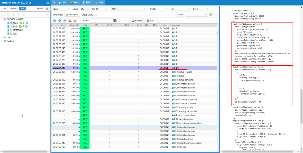
Check the SIB1 message to confirm that the random access parameters are broadcast as intended. The rach-ConfigCommon section defines the common PRACH configuration, including the PRACH configuration index, Msg1 FDM allocation, frequency start position, zero-correlation zone, target received power, preamble transmission limit, power ramping step, response window, SSB-to-PRACH mapping, and contention-resolution timer.
Also verify pusch-ConfigCommon because its common time-domain allocations and power-control parameters are used for uplink transmissions associated with the random access procedure and for PUSCH transmission after random access. In this example, the configuration includes Type-A PUSCH allocations with K2 values of 4 and the configured start-symbol-and-length settings. The same SIB1 also contains msgA-ConfigCommon, which provides the UE with the common MsgA PRACH and MsgA PUSCH resources required for 2-Step RACH.
Next, inspect the msgA-ConfigCommon IE in SIB1 to confirm the complete 2-Step RACH configuration broadcast to the UE. The rach-ConfigCommonTwoStepRA section defines the MsgA PRACH-related settings, including the MsgB response window, the number of contention-based preambles assigned to each SSB and shared RACH occasion, and the MsgA RSRP threshold used when selecting between 2-Step and 4-Step RACH.
The msgA-PUSCH-Config section defines the PUSCH resources associated with MsgA. It includes the MsgA MCS, the number of MsgA PUSCH occasions in time and frequency, the resource-block allocation, start symbol and duration, mapping type, guard band, frequency start position, and DMRS configuration. In this test, the configuration also indicates the available MsgA DMRS ports and that transform precoding is disabled. These parameters should match the intended two_steps_prach settings configured on the Callbox.
Next, inspect the lower-layer log to verify that the UE actually completed 2-Step RACH. Step 1 is identified by the PRACH transmission with two_steps=1, followed by the associated MsgA PUSCH carrying the initial uplink payload. The gNB detects the PRACH preamble and processes the PUSCH transmitted in the same MsgA procedure.
Step 2 is shown by the MsgB transmission over PDCCH and PDSCH. MsgB contains the random access response and contention-resolution information required to complete random access. The presence of the PRACH/PUSCH pair followed by the PDCCH/PDSCH pair confirms that the access procedure was completed using 2-Step RACH rather than the conventional 4-Step RACH procedure.
RRC / NAS Signaling
SIB1 (SA)
: This is the SIB1 message sent by gNB to configure parameters for NR 2 Step RACH. (
{
message c1: systemInformationBlockType1: {
cellSelectionInfo {
...
},
cellAccessRelatedInfo {
...
},
connEstFailureControl {
...
},
servingCellConfigCommon {
downlinkConfigCommon {
frequencyInfoDL {
...
},
initialDownlinkBWP {
genericParameters {
...
},
pdcch-ConfigCommon setup: {
...
},
pdsch-ConfigCommon setup: {
...
}
},
bcch-Config {
...
},
pcch-Config {
...
}
},
uplinkConfigCommon {
frequencyInfoUL {
...
},
initialUplinkBWP {
genericParameters {
...
},
rach-ConfigCommon setup: {
rach-ConfigGeneric {
prach-ConfigurationIndex 16,
msg1-FDM one,
msg1-FrequencyStart 7,
zeroCorrelationZoneConfig 15,
preambleReceivedTargetPower -110,
preambleTransMax n7,
powerRampingStep dB4,
ra-ResponseWindow sl10
},
ssb-perRACH-OccasionAndCB-PreamblesPerSSB one: n8,
ra-ContentionResolutionTimer sf64,
prach-RootSequenceIndex l839: 1,
restrictedSetConfig unrestrictedSet
},
pusch-ConfigCommon setup: {
...
},
pucch-ConfigCommon setup: {
...
},
msgA-ConfigCommon-r16 setup: {
rach-ConfigCommonTwoStepRA-r16 {
rach-ConfigGenericTwoStepRA-r16 {
msgB-ResponseWindow-r16 sl40
},
msgA-CB-PreamblesPerSSB-PerSharedRO-r16 16,
msgA-RSRP-Threshold-r16 56
},
msgA-PUSCH-Config-r16 {
msgA-PUSCH-ResourceGroupA-r16 {
msgA-MCS-r16 5,
nrofSlotsMsgA-PUSCH-r16 1,
nrofMsgA-PO-PerSlot-r16 one,
msgA-PUSCH-TimeDomainOffset-r16 4,
startSymbolAndLengthMsgA-PO-r16 27,
mappingTypeMsgA-PUSCH-r16 typeA,
guardBandMsgA-PUSCH-r16 0,
frequencyStartMsgA-PUSCH-r16 7,
nrofPRBs-PerMsgA-PO-r16 1,
nrofMsgA-PO-FDM-r16 four,
msgA-DMRS-Config-r16 {
msgA-PUSCH-NrofPorts-r16 1
},
nrofDMRS-Sequences-r16 1
},
msgA-TransformPrecoder-r16 disabled
}
}
},
timeAlignmentTimerCommon infinity
},
ssb-PositionsInBurst {
inOneGroup '80'H
},
...
},
ue-TimersAndConstants {
...
}
}
}