
NR NPN (Non Public Network)
This tutorial is to show you how to configure and test NR NPN. NPN (Non Public Network) is another word for Private Network. We have used the term Private Network since long again from 4G but the implementation of Private Network hadn't clearly been defined in 3GPP. Recently (in 3GPP Release 16) this feature is formally defined / specified in 3GPP with the name of NPN (Non Public Network). Even though I would not say every detailed implementation of NPN is defined in 3GPP, roughtly 3 or 4 different high level architecture of the implementation are frequently mentioned in various documents. Followings are a list of common architectures of NPN implementation. As of now, Amarisoft product support [A],[B],[D].
- [A] SNPN (Standalone Non-Public Network)
- [B] PNI-NPN (Public Network Integrated Non-Public Network) with Shared RAN
- [C] PNI-NPN (Public Network Integrated Non-Public Network) with Shared RAN and Core Network CP
- [D] PNI-NPN (Public Network Integrated Non-Public Network) with Shared RAN and Core Network CP & UP
Table of Contents
Introduction
Non-Public Networks (NPN), commonly referred to as Private Networks, represent a significant advancement in the evolution of mobile communications, particularly with the introduction of 5G New Radio (NR) technology. Traditionally, the deployment and management of private cellular networks lacked a standardized framework within 3GPP specifications, leading to fragmented implementations across industries and vendors. However, with the formalization of NPN in 3GPP Release 16, the telecommunications ecosystem now benefits from a unified set of guidelines and architectural models that define how private cellular networks can be deployed, managed, and integrated with public mobile networks. NPNs are designed to provide organizations—ranging from enterprises and factories to campuses and critical infrastructure—with dedicated, secure, and customizable wireless connectivity that leverages the high performance, low latency, and enhanced reliability of 5G NR. Architecturally, NPNs can be realized in several forms: as Standalone Non-Public Networks (SNPN), which are completely isolated from public mobile networks; or as Public Network Integrated Non-Public Networks (PNI-NPN), where the private network shares certain resources such as the Radio Access Network (RAN) or even core network components with the public operator. These flexible deployment options enable tailored solutions that can address stringent security, privacy, and performance requirements unique to diverse enterprise environments. The growing support for NPN in commercial products, such as those from Amarisoft, underscores its increasing relevance for industries seeking to harness the transformative potential of 5G through private network deployments. This tutorial provides a comprehensive guide on configuring and testing NR NPN, equipping learners with the foundational knowledge and hands-on skills necessary to navigate the intricacies of modern private 5G networks.
-
Context and Background
- NPNs, or Non-Public Networks, are standardized private 5G network solutions introduced in 3GPP Release 16.
- They enable enterprises to deploy customized, secure, and high-performance wireless networks separate from or in conjunction with public mobile operator infrastructure.
- Multiple architectural models exist for NPN deployment, including Standalone NPN (SNPN) and Public Network Integrated NPN (PNI-NPN), each offering varying levels of integration and resource sharing.
- NPNs address critical requirements for industries such as manufacturing, logistics, healthcare, and utilities, where control over connectivity, security, and data privacy is paramount.
-
Relevance and Importance of the Tutorial
- Provides step-by-step guidance for configuring and testing 5G NR NPNs using industry-standard approaches and commercially available solutions.
- Helps learners understand the fundamental concepts, architecture, and deployment scenarios for private 5G networks as defined by 3GPP.
- Equips professionals and engineers with practical skills to implement, validate, and troubleshoot NPN deployments in real-world environments.
- Addresses the growing demand for private 5G networks across multiple industry sectors, supporting digital transformation and Industry 4.0 initiatives.
-
Learning Outcomes
- Gain a comprehensive understanding of NPN architecture, deployment models, and integration options within the 5G NR ecosystem.
- Acquire hands-on knowledge for configuring NPN features using supported platforms and software.
- Learn to test and validate NPN deployments to ensure performance, security, and reliability.
- Develop the ability to assess use cases and requirements for different NPN architectures (e.g., SNPN, PNI-NPN).
-
Prerequisite Knowledge and Skills
- Foundational understanding of 5G NR technology and 3GPP standards.
- Basic familiarity with cellular network architecture, including RAN and Core Network components.
- Experience with network configuration and management tools is beneficial.
- Prior exposure to private network concepts and enterprise networking is helpful but not mandatory.
Summary of the Tutorial
This tutorial demonstrates low-layer testing of PNI-NPN (Public Network Integrated Non-Public Network) functionality in a single cell environment. The focus is on configuring, executing, and verifying the operation of PNI-NPN on an Amarisoft-based test system, with an option to use either a commercial UE or Amarisoft UEsim as the Device Under Test (DUT). The summary below details the test procedure, key configuration steps, and verification methodology as described in the tutorial.
- Test Setup
- The setup supports two options:
- Setup A: Using a commercial UE.
- Setup B: Using Amarisoft UEsim as the DUT (this is the one used in the walkthrough).
- The SIM card included with the system is used as-is. Configuration changes should follow the referenced Configuration Guide.
- The setup supports two options:
- Key Configuration Parameters
- Critical configuration parameters include:
- cag_info_list: Contains parameters such as plmn, cag_info, and network_name.
- network_name: To be set in relevant configuration files.
- Critical configuration parameters include:
- Test 1: PNI-NPN Single Cell
- This test verifies PNI-NPN operation within a single cell by configuring the network and DUT appropriately, then validating the correct NPN operation through logs and system outputs.
- Configuration Steps
- Prepare gNB (callbox) configuration by copying and modifying the base configuration file (e.g., gnb-sa-pni-npn-1.cfg).
- Configure network information for NPN, including cag_info_list parameter for SIB1 broadcast.
- Prepare and modify MME and UE database files (mme-ims-pni-npn-1.cfg and ue_db-ims-pni-npn-1.cfg), ensuring that plmn and cag_supported are set correctly and that ue_db entries match the expected PLMN and CAG IDs.
- On the UEsim, configure ue-nr-sa-pni-npn-1.cfg so that the cag_info_list matches the network and set as_release to 16 or higher (for commercial UE, this step is unnecessary; just ensure UE support for the relevant feature).
- Sample configuration entries for matching CAG IDs are provided, showing various orders of the cag_id_list.
- Test Execution Steps
- Start the LTE service on the callbox and verify the cell broadcast of multiple PLMNs as configured.
- Check which PLMN the AMF is connected to; ensure the DUT attempts to attach to a supported PLMN.
- Start trace logging to capture all relevant signaling messages and procedures.
- Power on the UE (or UEsim) and allow it to complete the initial attach procedure.
- Verify successful cell camping and initial attach for the NPN configuration. Detailed verification is performed by analyzing the trace and log files.
- Verification & Log Analysis
- Analyze logs to ensure:
- NG setup is completed, with gNB advertising the correct globalGNB-ID and broadcast PLMNs.
- SIB1 broadcasts correct plmn-IdentityInfoList and npn-IdentityInfoList as per configuration.
- UE selects and notifies the chosen CAG PLMN in the appropriate signaling message.
- gNB communicates selected CAG information to the core network.
- Core network responds with the attached PLMN via registration accept.
- Allowed CAG IDs are communicated to the gNB from the core network as per the database configuration.
- Analyze logs to ensure:
Summary of Methodology:
- Configure the test environment (callbox, core network, and UE/UEsim) to support PNI-NPN operation with the proper PLMN and CAG information in all relevant components.
- Run the test by powering up the system and UE, ensuring the UE camps on the correct cell and network broadcasts proper NPN identifiers.
- Use logs and trace analysis to verify each step of the procedure, confirming end-to-end signaling and configuration correctness.
- All critical configuration values (PLMN, CAG IDs, and support flags) must be consistent and correctly set across callbox, core network, and UE configurations.
Test Setup
Test setup for this tutorial is as shown below. This is just for low layer testing, you may not need any complicated IP layer setup.
- SIM Card used in this tutorial is the one delivered with the system as it is.
- If you want to change the configuration, The tutorial Configuration Guide would help
Use Setup A for a commercial UE or Setup B for Amarisoft UEsim. In this test, Setup B is used.
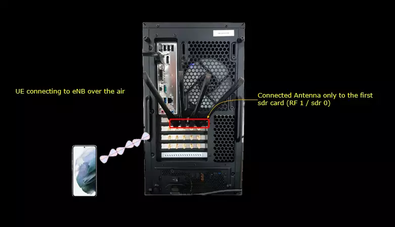
Setup A
This is the setup for the case where you use a commercial phone as DUT.
The callbox has four antennas connected to its SDR board. The phone talks to the callbox over the air.
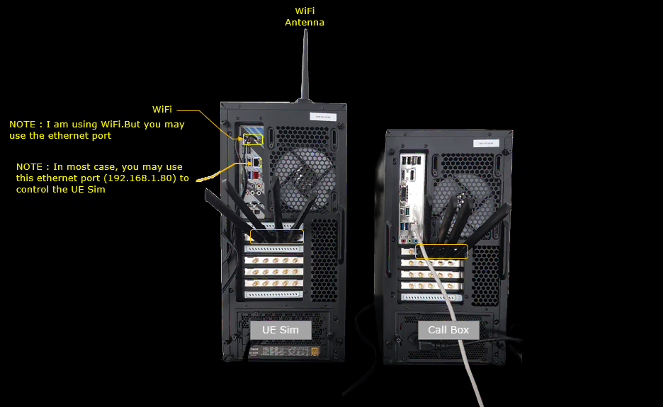
Setup B
This is the setup for the case where you use Amarisoft UEsim as DUT.
The SDR board of the callbox and the SDR board of UEsim are connected directly with four RF cables. No antenna is used in this setup.
Key Configuration Parameters
Followings are important configuration parameters for this tutorial. You may click on the items for the descriptions from Amarisoft documents.
- cag_info_list : In this link, you can find the descriptions for all the parameters below.
- plmn
- cag_info
- network_name
- network_name
- cag_info_list (ue_db) : the CAG plmns and cag_id_list allowed for the UE, with cag_only_ind for each plmn
- cag_info_list (UEsim ue_list) : the CAG plmn and cag_id_list that the simulated UE uses
- as_release (UEsim ue_list) : set to 16 or greater for NPN
Test 1 : PNI-NPN Single Cell
This test show a test case where you configure PNI-NPN (Public Network Integrated Non-Public Network) in single cell and verify the operation.
Configuration
The configuration shown here is common configuration for all the subtests belonging to Test 1 and I will not show this configuration repeatedly for every subtest.
I have used gnb-sa-pni-npn-1.cfg which is copied and modified from gnb-sa.cfg on Callbox (gNB)
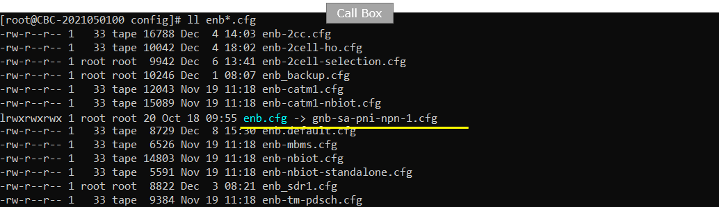
I am using mme-ims-pni-npn-1.cfg and ue_db-ims-pni-npn-1.cfg which are copied from mme-ims.cfg and ue_db-ims.cfg respectively.
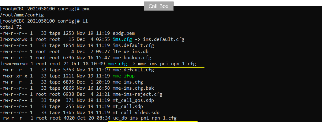
On UEsim, I used ue-nr-sa-pni-npn-1.cfg which has been copied and modified from ue-nr-sa.cfg (
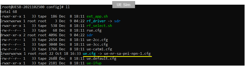
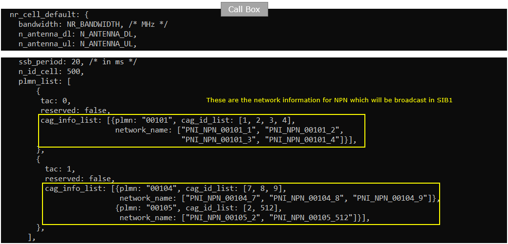
gnb-sa-pni-npn-1.cfg is configured as follows.
Configure network information for NPN which will be broadcast in SIB1 using cag_info_list parameter.
The plmn_list in nr_cell_default has two entries. The first entry has tac 0 and one cag_info_list item. It is plmn 00101 with cag_id_list [1, 2, 3, 4]. Each CAG ID has its own network_name, from PNI_NPN_00101_1 to PNI_NPN_00101_4.
The second entry has tac 1 and two cag_info_list items. Plmn 00104 uses cag_id_list [7, 8, 9] with the network names PNI_NPN_00104_7 to PNI_NPN_00104_9. Plmn 00105 uses cag_id_list [2, 512] with the network names PNI_NPN_00105_2 and PNI_NPN_00105_512. Both entries are set with reserved: false.
If you want to broadcast a different CAG, change the plmn and the cag_id_list here. Keep one network_name for each CAG ID, in the same order as in this example.
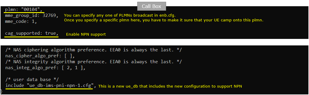
mme-ims-pni-npn-1.cfg is configured as shown below.
Specify the plmn to which UE is supposed to camp on and enable NPN support by setting cag_supported : true. Then include a ue_db that carries the cag_info_list.
In this configuration plmn is set to "00104". You can specify any one of the PLMNs broadcast in enb.cfg. Here it is the first plmn of the second plmn_list entry. Once you set a specific plmn here, you have to make sure that your UE camps onto this plmn. mme_group_id 32769 and mme_code 1 are left as they are.
cag_supported: true enables NPN support in the core network. At the end of the file, the user data base comes from include "ue_db-ims-pni-npn-1.cfg". This is a new ue_db with the configuration to support NPN.
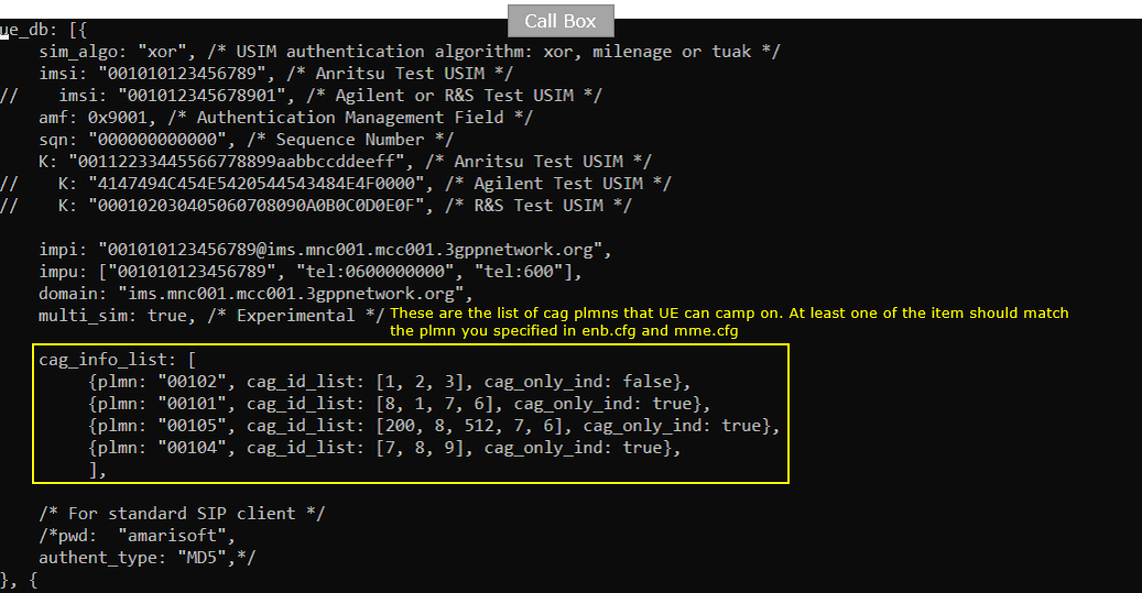
ue_db-ims-pni-npn-1.cfg is configured as shown below.
In the ue_db, there should be at least one item that should match the plmn specified in enb.cfg and mme.cfg.
The ue_db entry is for imsi 001010123456789 with sim_algo "xor" and the K of the Anritsu test USIM. Its cag_info_list is the list of CAG plmns that the UE can camp on. Each item has a plmn, a cag_id_list and cag_only_ind.
Plmn 00102 has cag_id_list [1, 2, 3] with cag_only_ind: false. The gNB does not broadcast this plmn in this test. Plmn 00101 has [8, 1, 7, 6], plmn 00105 has [200, 8, 512, 7, 6] and plmn 00104 has [7, 8, 9]. These three are set with cag_only_ind: true.
The item for 00104 matches the plmn in mme.cfg. Its CAG IDs 7, 8 and 9 are the same as the gNB broadcasts for 00104. Plmn 00101 shares only CAG ID 1 with enb.cfg, and plmn 00105 shares only CAG ID 512.
{plmn: "00104", cag_id_list: [7, 80, 90], cag_only_ind: true}
{plmn: "00104", cag_id_list: [80,7, 90], cag_only_ind: true}
{plmn: "00104", cag_id_list: [80,90, 7], cag_only_ind: true}
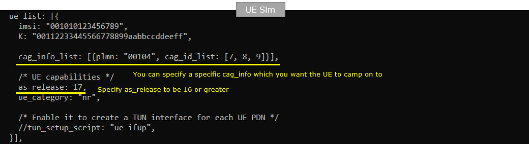
ue-nr-sa-pni-npn-1.cfg is configured as shown below.
The ue in the ue_list should carry a cag_info_list that match the camping cag specified in callbox (enb.cfg and mme.cfg) and set as_release to 16 or higher (
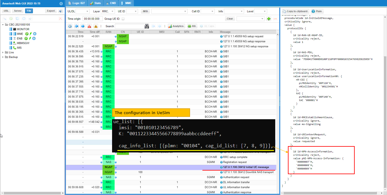
The UE has imsi 001010123456789 and the same K as the ue_db entry on the callbox. Its cag_info_list has one item, plmn "00104" with cag_id_list [7, 8, 9]. You can specify here the specific cag_info you want the UE to camp onto. In this test it is the plmn of mme.cfg with the CAG IDs that the gNB broadcasts for it.
as_release is set to 17 and ue_category is "nr". The NPN information in SIB1 uses Rel-16 elements, so as_release has to be 16 or greater. If you want the UE to camp on another CAG, change the plmn and cag_id_list here. Then change the plmn in mme.cfg to the same value.
Perform the Test
Run lte service on callbox and check 'cell' command. You would notice the multiple PLMNs you configured in enb.cfg as shown below. Note that the plmn in cell command output shows all the plmns specified in cell configuration.
The cell phy command shows the cell in band n78 with 20 MHz bandwidth and 30 kHz SCS. The DL ARFCN is 632628 and the SSB ARFCN is 632544. The header line shows PLMN=00101 and gNB_ID=0x12345.
The cell command shows pci 500 and TAC 00000000. The plmn column lists 00101 00104 00105. These are the plmn values of the cag_info_list items in enb.cfg.

Check which PLMN is connected to AMF as shown below. If DUT try to attach to different PLMN from the one shown below, it will be rejected by core network (AMF).
The ng command shows the NG connection to the AMF at 127.0.1.100:38412 with state=setup_done. PLMN=00104 is the plmn set in mme.cfg. In this test the DUT has to register on 00104.

Now start trace logging.
The t command on the gNB console starts the trace. Press [return] when you want to stop it.

Power on UE on UEsim (If your DUT is a commercial phone, turn on the phone)
UEsim runs RF0 with sample_rate 23.040 MHz and dl_freq and ul_freq 3489.420 MHz in band n78. The log command sets file.rotate=250M and file.path=/var/log/lte/. After power_on, the UE reports Cell 0: SIB found.

Wait until the DUT complete the initial attach. If UE successfully camp onto the cell, you may assume that NPN works but the details should be verified from the captured log. Not much details in the trace log shown here.
The gNB detects a PRACH on cell 01 with seq=5, ta=2 and snr=21.3 dB. Then the UE with RNTI 4601 appears in the trace. The first DL line shows cqi 15 and mcs 18.8, and the UL snr is 36.9. This only tells you that the UE is connected. Which PLMN and CAG the UE selected has to be checked in the log.

Log Analysis
Following is the log snapshot that are involved in UE assistance information message and handling process.
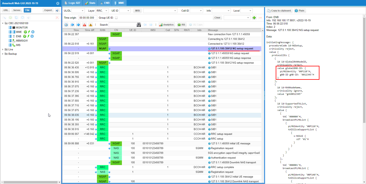
Make if NG setup process is properly completed with NGAP log. Here you see gNB notifies plmn 001-01 as globalGNB-ID and notifies 001-01,001-04,001-05 as broadcast PLMNs.
The gNB sends the NG setup request at 06:56:22.518 and the AMF answers with NG setup response. In id-GlobalRANNodeID, globalGNB-ID carries pLMNIdentity '00F110'H and gNB-ID '0012345'H. '00F110'H is the encoded form of 001-01.
In id-SupportedTAList, tAC '000000'H has a broadcastPLMNList with pLMNIdentity '00F110'H. tAC '000001'H has pLMNIdentity '00F140'H, which is 001-04. Each TAC is the tac of the matching plmn_list entry in enb.cfg.
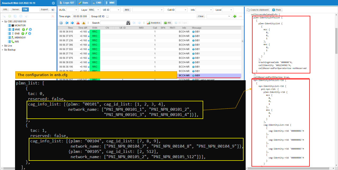
Then confirm that the plmn-IdentityInfoList and npn-IdentityInfoList in SIB1 is broadcast as configured in enb.cnf.
Here you see PLMN 001-01 is broadcast in plmn-IdentityInfoList and in npn-IdentityInfoList.
SIB1 is first sent at 06:56:36.435 and repeats every 160 ms. In cellAccessRelatedInfo, plmn-IdentityInfoList has mcc 001 and mnc 01 with trackingAreaCode '000000'H and cellIdentity '001234501'H.
In npn-IdentityInfoList-r16, the first pni-npn-r16 entry has plmn-Identity-r16 001-01. Its cag-IdentityList-r16 has '00000001'H, '00000002'H, '00000003'H and '00000004'H. These are the CAG IDs 1, 2, 3 and 4 of the first cag_info_list in enb.cfg.
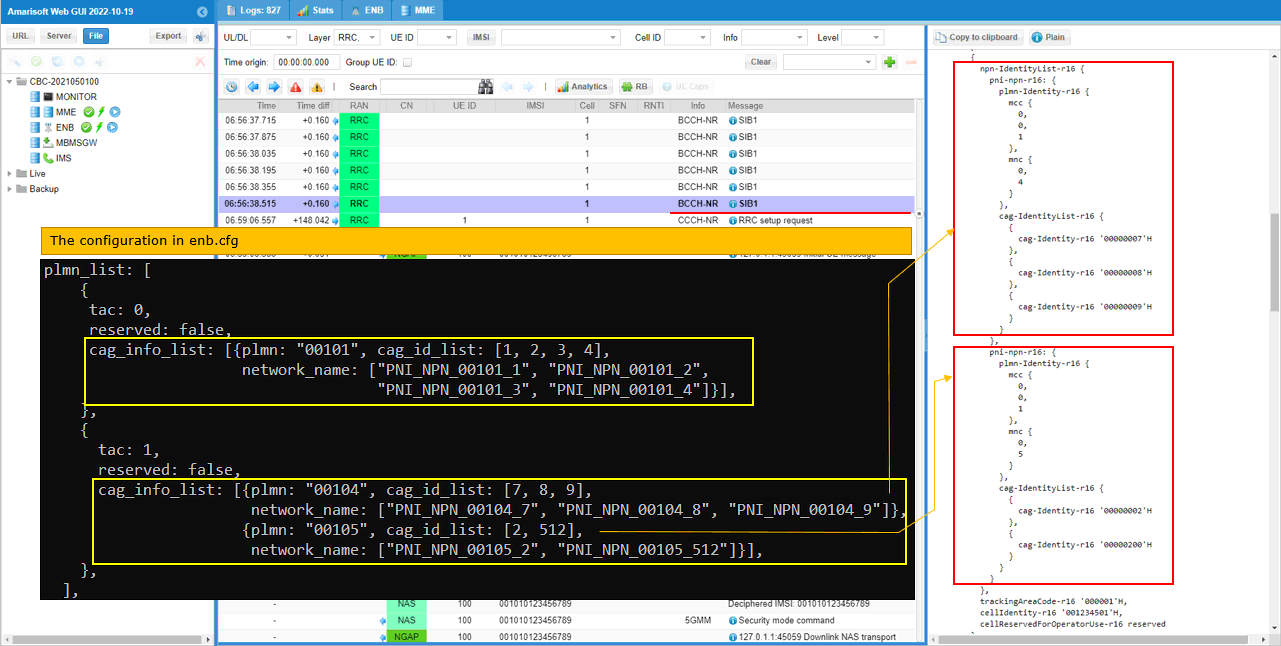
Here you see PLMN 001-04 and 001-05 are listed in npn-IdentityInfoList as specified in enb.cfg
Plmn 001-04 carries cag-Identity-r16 '00000007'H, '00000008'H and '00000009'H. Plmn 001-05 carries '00000002'H and '00000200'H. The CAG IDs are encoded in hexadecimal, so '00000200'H is the 512 in enb.cfg.
This npn-IdentityInfo entry has trackingAreaCode-r16 '000001'H. That is the tac 1 of the second plmn_list entry. cellIdentity-r16 is the same '001234501'H as in the first entry.
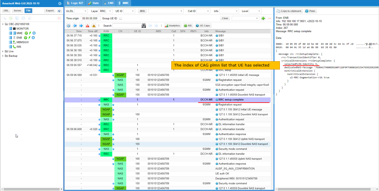
When UE camp on, it notifies that the CAG plmn it selected via selectedPLMN-Identity IE in RRC setup Complete message.
In this run the RRC setup complete is sent on DCCH-NR with selectedPLMN-Identity 5. This value is the index of the CAG plmn list that the UE has selected. It is not the PLMN code itself. The PLMN behind this index is confirmed in the NGAP and NAS messages that follow.
Based on the cag plmn selection from the UE, gNB notifies about the selected cag information to core network via pNI-NPN-Access-Information IE in NGAP message (Initial UE message).
In the Initial UE message, id-NPN-AccessInformation carries pNI-NPN-Access-Information with '00000007'H, '00000008'H and '00000009'H. These are the cag_id_list [7, 8, 9] for plmn 00104 in the cag_info_list of the UE in UEsim.
In id-UserLocationInformation, the tAI has pLMNIdentity '00F140'H and tAC '000001'H. The nR-CGI keeps pLMNIdentity '00F110'H with nRCellIdentity '001234501'H. The RRC establishment cause is mo-Signalling.
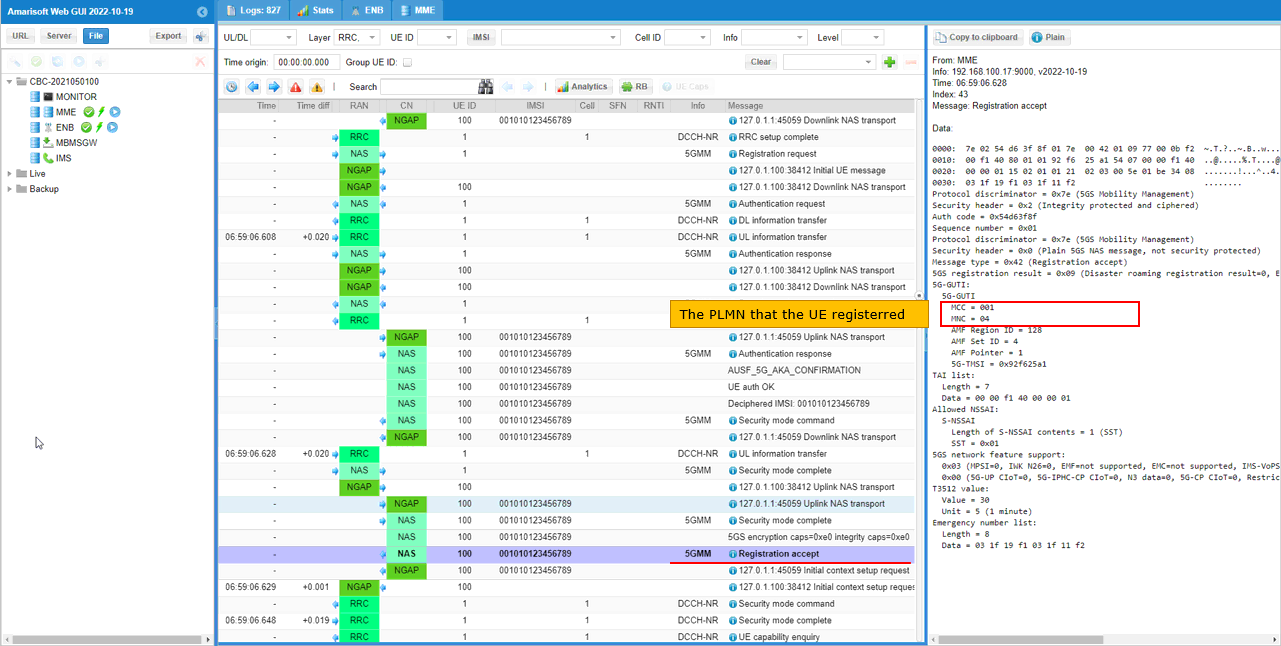
Then Network notifies the attached PLMN back to UE via 5G-GUTI in Registration Accept message.
The 5G-GUTI in the Registration accept has MCC = 001 and MNC = 04. This is the PLMN that the UE registered on, and it is the plmn 00104 set in mme.cfg. The rest of the 5G-GUTI is AMF Region ID 128, AMF Set ID 4 and AMF Pointer 1.
The TAI list has the data 00 00 f1 40 00 00 01. This is the same PLMN 001-04 with TAC 000001.
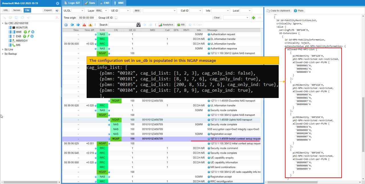
Core Network notifies gNB of all the plmn as associated cag id list via allowed-PNI-NPI-List in the NGAP message Initial Context Setup Message. The information in this list is configured by cag_info_list specified in ue_db.
id-MobilityRestrictionList has servingPLMN '00F140'H. In its iE-Extensions, id-NPN-MobilityInformation carries pNI-NPN-MobilityInformation with allowed-PNI-NPI-List. There is one item for each cag_info_list item in ue_db.
pLMNIdentity '00F120'H is plmn 00102. It has pNI-NPN-restricted not-restricted and the allowed CAG list '00000001'H to '00000003'H. This comes from cag_only_ind: false. The other three items, '00F110'H, '00F150'H and '00F140'H, are restricted. They come from cag_only_ind: true.
The CAG IDs are in hexadecimal and keep the order of cag_id_list. For plmn 00105, 200 becomes '000000C8'H and 512 becomes '00000200'H.
RRC / NAS Signaling
This section has the decoded RRC messages that carry the NPN information in this test. SIB1 carries the CAG plmns and CAG IDs of the cell. RrcSetupComplete carries the index of the CAG plmn that the UE selected.
SIB1 (SA)
: This is SIB1 containing npn configurations
{
message c1: systemInformationBlockType1: {
cellSelectionInfo {
...
},
cellAccessRelatedInfo {
plmn-IdentityInfoList {
{
plmn-IdentityList {
{
mcc {
0,
0,
1
},
mnc {
0,
1
}
}
},
trackingAreaCode '000000'H,
cellIdentity '001234501'H,
cellReservedForOperatorUse notReserved
}
},
cellReservedForOtherUse true,
npn-IdentityInfoList-r16 {
{
npn-IdentityList-r16 {
pni-npn-r16: {
plmn-Identity-r16 {
mcc {
0,
0,
1
},
mnc {
0,
1
}
},
cag-IdentityList-r16 {
{
cag-Identity-r16 '00000001'H
},
{
cag-Identity-r16 '00000002'H
},
{
cag-Identity-r16 '00000003'H
},
{
cag-Identity-r16 '00000004'H
}
}
}
},
trackingAreaCode-r16 '000000'H,
cellIdentity-r16 '001234501'H,
cellReservedForOperatorUse-r16 reserved
},
{
npn-IdentityList-r16 {
pni-npn-r16: {
plmn-Identity-r16 {
mcc {
0,
0,
1
},
mnc {
0,
4
}
},
cag-IdentityList-r16 {
{
cag-Identity-r16 '00000007'H
},
{
cag-Identity-r16 '00000008'H
},
{
cag-Identity-r16 '00000009'H
}
}
},
pni-npn-r16: {
plmn-Identity-r16 {
mcc {
0,
0,
1
},
mnc {
0,
5
}
},
cag-IdentityList-r16 {
{
cag-Identity-r16 '00000002'H
},
{
cag-Identity-r16 '00000200'H
}
}
}
},
trackingAreaCode-r16 '000001'H,
cellIdentity-r16 '001234501'H,
cellReservedForOperatorUse-r16 reserved
}
}
},
connEstFailureControl {
...
},
servingCellConfigCommon {
...
},
ue-TimersAndConstants {
...
}
}
}
RrcSetupComplete (SA)
: This is RrcSetupComplte message showing the cag plmn that UE selected
{
message c1: rrcSetupComplete: {
rrc-TransactionIdentifier 0,
criticalExtensions rrcSetupComplete: {
selectedPLMN-Identity 5,
dedicatedNAS-Message '7E004179000D0100F110F0FF000010325476982E02E0E0'H,
nonCriticalExtension {
nonCriticalExtension {
ul-RRC-Segmentation-r16 true
}
}
}
}
}