NR LPP (NR Positioning Protocol)
This tutorial is to show how to configure and test LPP. LPP stands for NR Positioning Protocol and it is a mechanism to facilitate the exchange of positioning information between the mobile device and the network. Conceptually in terms of the purpose LPP is similar to SUPL(Secure User Plane Location). Main differences from SUPL would be
- LPP can be associated not only with GPS but also with other system like GLONASS, Galileo, and QZSS etc whereas SUPL is mainly associated with GPS
- LPP support the information exchange not only via U-plane but also via C-Plane whereas SUPL supports U-Plane only.
- LPP is supported in LTE and NR, whereas SUPL is supported in 3G/4G.

- Only C-Plane LPP is supported (U-Plane LPP is not supported)
Table of Contents
Introduction
The NR Positioning Protocol (LPP) is a key component in 5G and LTE networks, designed to enable precise location-based services by facilitating the efficient exchange of positioning information between mobile devices (User Equipment, UE) and the network. Unlike its predecessor, SUPL (Secure User Plane Location), which primarily leverages the user plane and is closely tied to GPS, LPP offers a multi-constellation approach—supporting not only GPS but also other global navigation satellite systems (GNSS) such as GLONASS, Galileo, and QZSS. Architecturally, LPP operates in both the control plane (C-Plane) and user plane (U-Plane), allowing it to flexibly adapt to diverse deployment scenarios and use cases within LTE and 5G NR ecosystems. This dual-plane capability enhances the reliability and accuracy of positioning, making LPP an essential protocol for enabling advanced applications like emergency services, asset tracking, and network-based location analytics. LPP's integration into the radio access and core network layers leverages standardized signaling procedures to ensure interoperability, security, and scalability across devices and network vendors. As 5G networks continue to evolve, LPP's role in providing accurate, low-latency positioning data becomes increasingly significant, underpinning innovations in autonomous systems, smart cities, and mission-critical communications. In this tutorial, we explore the configuration and testing of LPP, with a particular focus on Amarisoft's implementation, highlighting current limitations and supported features to provide a practical, hands-on understanding of modern cellular positioning protocols.
-
Context and Background
- LPP is the standardized protocol for positioning in LTE and 5G NR, supporting advanced location services beyond traditional GPS.
- Facilitates multi-constellation GNSS support, enhancing accuracy and service robustness in urban and challenging environments.
- Operates over both control plane (C-Plane) and user plane (U-Plane), improving flexibility and enabling a wider range of network deployment options.
- Supersedes SUPL in modern networks, addressing the growing demand for secure and reliable positioning in next-generation mobile applications.
-
Relevance and Importance
- Essential for regulatory compliance such as E911, providing accurate location for emergency services.
- Enables critical use cases in IoT, logistics, autonomous vehicles, and augmented reality where precise positioning is a core requirement.
- Supports advanced features in 5G NR, including low-latency services and network-assisted positioning enhancements.
- Amarisoft's LPP implementation allows for practical evaluation and development of positioning-enabled solutions in a controlled test environment.
-
Learning Outcomes
- Understand the architectural principles and functional workflow of LPP in LTE and 5G NR networks.
- Learn how to configure and test LPP using Amarisoft software, with emphasis on current capabilities and limitations.
- Gain insights into GNSS system integration, dual-plane signaling, and the practical aspects of protocol interoperability.
- Develop skills to troubleshoot and validate positioning procedures in modern cellular networks.
-
Prerequisite Knowledge
- Basic understanding of LTE and 5G NR network architecture and signaling procedures.
- Familiarity with GNSS technologies and location-based service concepts.
- Experience with Amarisoft or similar cellular network test platforms is beneficial but not mandatory.
- General knowledge of protocol testing and network configuration is recommended for hands-on sections.
Summary of the Tutorial
This tutorial details the test procedures for verifying NR LPP (LTE Positioning Protocol) functionalities using Amarisoft Callbox and UEsim. The following summarizes the test setup, configuration, and procedural steps required to perform the test and analyze the results.
-
Test Setup:
- Two alternative setups are described: using a commercial UE as the Device Under Test (DUT), or using Amarisoft UEsim as DUT.
- The SIM card provided with the system is used by default; configuration changes are possible as referenced in the Configuration Guide.
-
Key Configuration Parameters:
- Critical parameters for NL1 and LMF configuration are listed, such as nl1.api_root, nl1.transaction_timeout, lmf_cfg.lpp_test, lmf_cfg.periodic_meas, lmf_cfg.meas_period, lmf_cfg.otdoa_assistance_data, lmf_cfg.nr_tdoa_assistance_data, and lmf_cfg.autonomous_mode.
-
Configuration Procedures:
-
Callbox (gNB) Configuration:
- Use the gnb-sa.cfg configuration file as-is; TDD mode and 20MHz bandwidth are set for NR Band 78.
- Set dl_nr_earfcn as required for the chosen frequency band.
-
MME Configuration:
- Copy and modify mme-ims.cfg to create mme-ims-nr-lpp.cfg.
- Configure a test LMF using the lmf_cfg parameter for cases where external LMF is not used.
-
UEsim Configuration:
- Copy and modify ue-nr-sa.cfg to create ue-nr-sa-lpp.cfg, ensuring TDD and 20MHz bandwidth are configured.
- Set ground_position_at_origin within cell_groups to enable UEsim to respond to nr_location_req.
- Use default ue_list configuration as required.
-
Callbox (gNB) Configuration:
-
Test Execution Steps:
- Verify cell configuration using 'cell phy' and 'cell' commands to ensure settings are as intended.
- Switch to the (mme) interface and execute the 'nl1' command; confirm LCS connection state is 'state=connected'.
- Power on the UE in the UEsim and confirm successful initial attach procedure.
-
LMF Subscription:
- On Callbox send a command to subscribe the LMF server to N1/N2 messages for a specific UE:
- On Callbox send a command to subscribe the LMF server to N1/N2 messages for a specific UE:
-
Initiate Location Procedure:
- Send the nr_location_req command to initiate the location procedure for the target UE:
- Request ECID and GNSS reports individually
- Send the nr_location_req command to initiate the location procedure for the target UE:
-
Log Analysis:
- Monitor log files for NL1, MME, LMF, and UE event sequences. Key checkpoints include:
- NL1 interface listening upon gNB startup.
- Initial UE registration completion.
- HTTP transactions for establishing LMF-AMF connections and N1/N2 message subscriptions.
- HTTP and NAS transactions corresponding to LPP request/response sequences for capability and location information exchanges.
- Verification of successful message exchanges via status codes and message reception indications.
Note: The tutorial provides comprehensive step-by-step procedures, including configuration, remote API command usage, log analysis, and expected transaction flows for validating NR LPP ECID and GNSS location procedures. All command-line and configuration steps must be followed exactly as described to ensure successful test outcomes.
Test Setup
Test setup for this tutorial is as shown below.
- SIM Card used in this tutorial is the one delivered with the system as it is.
- If you want to change the configuration, The tutorial Configuration Guide would help
Setup A
This is the setup where you use a commercial UE as DUT.

Setup B
This is the setup where you use a commercial Amarisoft UEsim as DUT.

Key Configuration Parameters
Followings are important configuration parameters for this tutorial. You may click on the items for the descriptions from Amarisoft documents.
Test 1 : ECID with Amarisoft UEsim
Configuration
I have used gnb-sa-lpp-ecid.cfg on Callbox (gNB) as it is without any modification.

I am using the mme-ims-nr-lpp-auto.cfg which is copied and modified from mme-ims.cfg

I have used ue-nr-sa-lpp-ecid.cfg on UEsim which is copied and modified from ue-nr-sa.cfg.

For eNB configuration, there is no specific parameters you need to set. Just use gnb-sa-lpp-ecid.cfg without any modification.
This test targets NR eCID measurement. The implementation requires at least two NR cells, so N_CELLS is set to 2 to provide a serving cell plus a neighbor cell for measurement. The setup selects an NR TDD configuration and a defined NR channel bandwidth so the test runs with a known numerology and resource grid size. The RF chain is also constrained by an IF attenuation setting, so the received level stays within the expected range for stable measurements.
This test does not use PRS. For NR eCID, the position-related result is derived from timing and cell identity based measurements rather than PRS correlation, so ENABLE_PRS is set to 0 to keep the procedure simple and avoid PRS scheduling and PRS resource configuration. The antenna settings define the DL and UL port usage for the call box and UE, and SRS is disabled unless you explicitly need uplink sounding for another part of the test. Overall, the configuration keeps only the minimum items needed for NR eCID in an LPP session and turns off PRS-related features to reduce variables during verification.

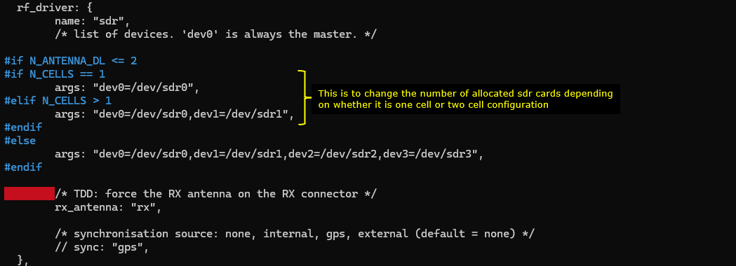
This configures the RF driver block so the call box knows which SDR devices to open and how many to allocate for the test. The driver name is set to sdr, so the software uses the SDR backend and expects device nodes like /dev/sdr0, /dev/sdr1, and so on.
If the downlink antenna count is 4 or more, it allocates four SDR devices and maps them to dev0 through dev3. Otherwise it checks the number of NR cells. If you run a single cell configuration, it uses only dev0. If you run a multi cell configuration, it allocates dev0 and dev1 so each cell can be served by its own SDR path. This is why N_CELLS impacts how many SDR cards are assigned.

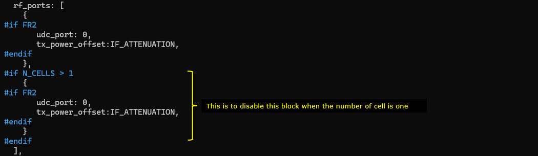
This part defines the RF port mapping for the test so the software can build the correct set of transmit and receive paths for each NR cell.
The first RF port entry is always present. The second RF port entry is included only when N_CELLS is greater than 1. This is the mechanism that makes the same configuration file work for both one cell and two cell setups. If you run only one cell, the second port block is used, so there is no unused port and no extra SDR resource allocation. If you run two cells, the second port block becomes active.
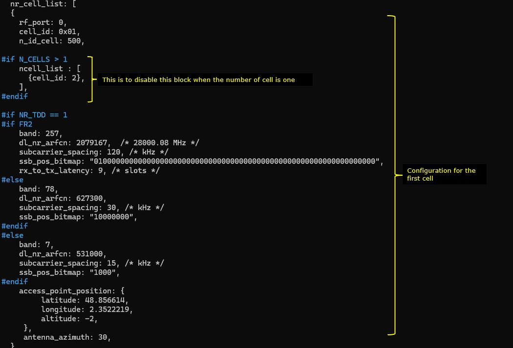
This configuration defines the NR cell used in the LPP eCID session. The key parameters are n_id_cell, dl_nr_arfcn, subcarrier_spacing, and ssb_pos_bitmap. n_id_cell determines the PCI and therefore which cell the UE camps on and measures. dl_nr_arfcn and band set the RF frequency for the test. subcarrier_spacing sets the numerology that impacts timing and measurement behavior. ssb_pos_bitmap controls which SSB locations are transmitted, so it affects initial access and measurement stability.
For two cell eCID, ncell_list is the important parameter. It enables the neighbor cell definition only when N_CELLS > 1. Without ncell_list, the setup becomes a single cell configuration and eCID neighbor based measurement is not possible.
For LPP validation, access_point_position is the important block. latitude, longitude, and altitude provide the reference cell site position used for positioning messages and result checking.
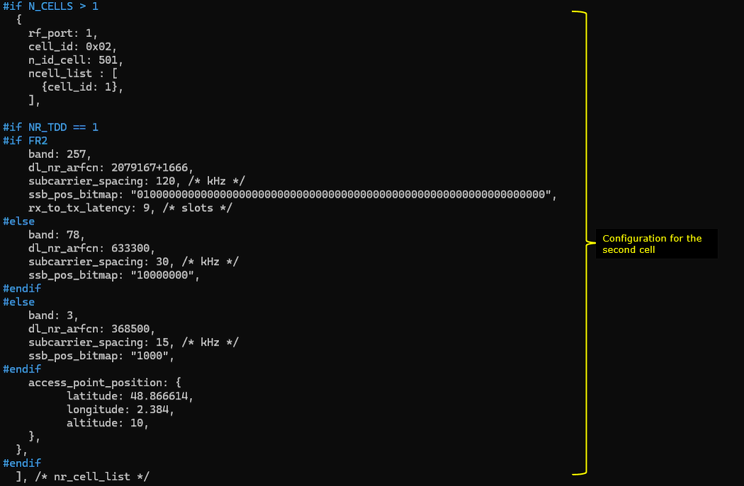
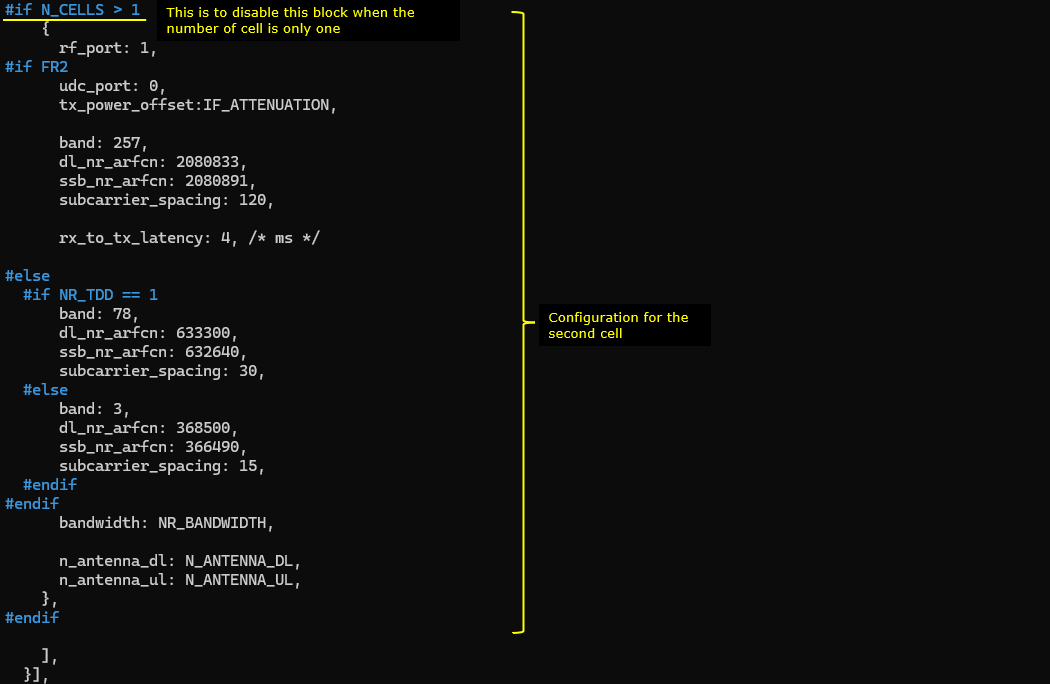
This block adds the second NR cell only when N_CELLS > 1, which is required for NR eCID. The key parameters are rf_port, n_id_cell, dl_nr_arfcn, subcarrier_spacing, ssb_pos_bitmap, and ncell_list. rf_port maps this cell to the second RF chain. n_id_cell sets the PCI for this second cell. band and dl_nr_arfcn place it on a different frequency from the first cell. subcarrier_spacing and ssb_pos_bitmap make the SSB detectable for camping and measurements. ncell_list links the cells so the neighbor relationship exists for eCID reporting. access_point_position with latitude, longitude, and altitude defines the reference location of this second cell for LPP validation.
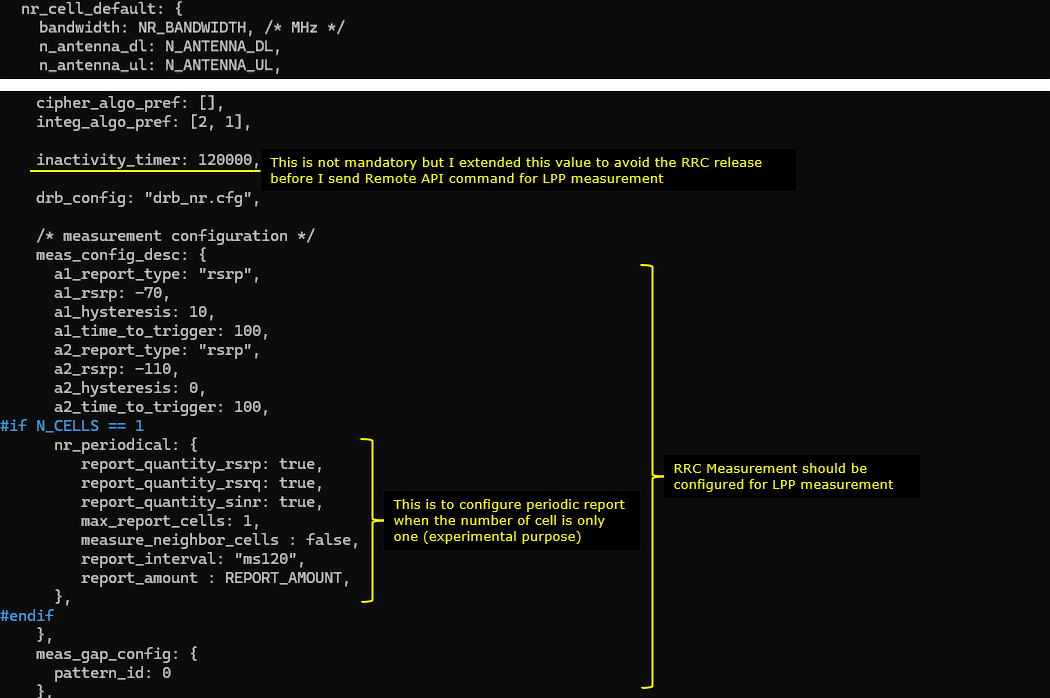
This block defines default NR cell behavior and the measurement settings needed before running the LPP procedure.
The inactivity_timer is extended to prevent the UE from going idle and triggering RRC release before you send the Remote API command that starts the LPP measurement.
The important part is meas_config_desc. This is where the RRC measurement framework is enabled, with A1 and A2 thresholds and time_to_trigger values that control when measurements are considered stable. For a single cell setup only, nr_periodical enables periodic measurement reports(this is experimental purpose). The key parameters there are report_quantity_rsrp, report_quantity_rsrq, report_quantity_sinr, report_interval, report_amount, and max_report_cells. These ensure the UE keeps producing measurement results that the LPP eCID procedure can use.
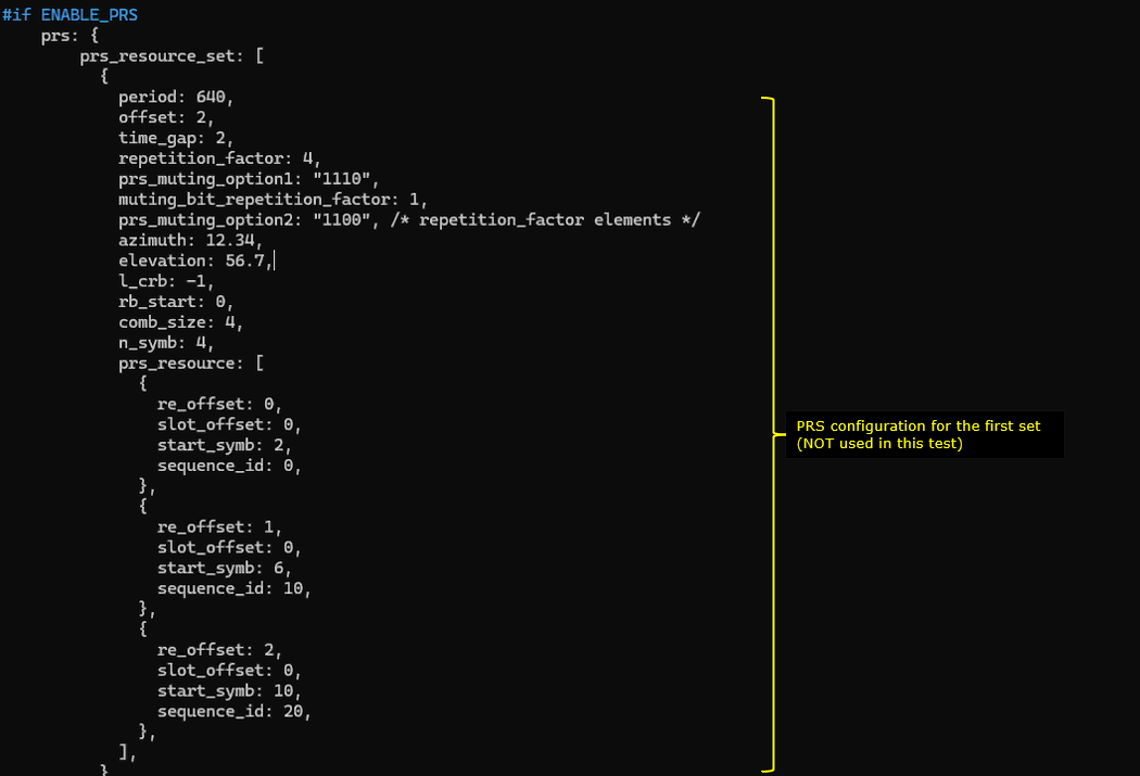
This block is the NR PRS configuration and it is used only when ENABLE_PRS is enabled. In this LPP eCID test, PRS is not used, so this section is kept as a template but remains inactive.
If you enable it, prs_resource_set defines when PRS is transmitted and how it is shaped. period, offset, time_gap, and repetition_factor control the PRS periodicity and repetition pattern. prs_muting_option1, muting_bit_repetition_factor, and prs_muting_option2 control muting so PRS can be selectively turned on and off across occasions. l_crb, rb_start, comb_size, and n_symb define the PRS frequency and time resource footprint. azimuth and elevation describe the beam direction metadata used for positioning related interpretation.
prs_resource then defines the actual PRS resources inside the set. re_offset, slot_offset, and start_symb place each PRS resource within the PRS occasion. sequence_id selects the PRS sequence identity so multiple resources can use different sequences.
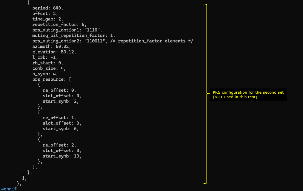
This is another PRS resource set definition. It is meant to describe a second PRS transmission pattern, but it is still under the same ENABLE_PRS condition, so it stays inactive in this eCID based LPP test.
The key parameters are period, offset, time_gap, and repetition_factor. They define how often PRS occasions appear and how many consecutive occasions are repeated. prs_muting_option1, muting_bit_repetition_factor, and prs_muting_option2 define which occasions are muted, so you can create on off patterns across the repeated PRS occasions. l_crb and rb_start define where PRS is placed in frequency, and comb_size with n_symb define the PRS density and time length.
Inside prs_resource, re_offset selects the PRS comb offset, and slot_offset and start_symb place each PRS resource inside the slot. Multiple entries let you transmit PRS in different OFDM symbols within the same PRS occasion, which is useful when you want more PRS energy or different measurement opportunities. Azimuth and elevation are metadata for the beam direction associated with this PRS set.
In mme-ims-nr-lpp-auto.cfg , In case where you want to use Amarisoft mme for the testing purpose without using external LMF, you can configure a test LMF with the parameter lmf_cfg.
lmf_cfg configures the internal test LMF that is embedded in the AMF. It is not a real production location server. It exists to drive and debug positioning procedures through simple APIs.
autonomous_mode controls whether the LMF runs the whole procedure by itself. If autonomous_mode is true, the LMF automatically starts the needed NRPPa and LPP exchanges when it receives a location request, so you do not need to manually call step by step APIs. If autonomous_mode is false, the LMF only sends the first trigger message and then waits for you to invoke the follow up APIs to continue.
ran_node_id_list is required when autonomous_mode is enabled. It tells the LMF which gNB to address in the HTTP request, using plmn, gnb_id_bits, and gnb_id. If this list is missing or incorrect, the autonomous procedure cannot target the right RAN node.

In ue-nr-sa-lpp-ecid.cfg , TDD is used and bandwidth is set to 40 Mhz (CELL_BANDWIDTH 40).
This section sets the high level UE simulator parameters that must match the network side configuration for an NR LPP eCID test. N_CELLS is set to 2. This is the key requirement for NR eCID in this setup because the procedure needs at least a serving cell and one neighbor cell to produce meaningful eCID measurements. NR_TDD selects the NR TDD profile used by the UE simulator. It must be consistent with the gNB configuration so the UE can synchronize, camp, and keep UL and DL timing aligned during the measurement session. N_ANTENNA_DL and N_ANTENNA_UL define the UE antenna configuration for downlink and uplink. These settings control whether the UE runs as SISO or with diversity reception on the downlink, and they affect measurement quality and stability.

This block configures which SDR devices the UE simulator will open and how they are mapped to logical device instances.
The driver selection depends on N_ANTENNA_DL and N_CELLS. When N_ANTENNA_DL is 2 or less, the number of SDR devices is mainly driven by how many cells you run. If N_CELLS is 1, only dev0 is allocated. If N_CELLS is greater than 1, dev0 and dev1 are allocated so the UE simulator can support the two cell test topology. When N_ANTENNA_DL is larger, more SDR devices are allocated, up to dev0 through dev3, to support additional RF chains.
This block defines the NR cell group and the first NR cell that the UE simulator will use during the LPP eCID session.
group_type set to nr tells the UE simulator that this group is NR. multi_ue set to true allows multiple UE contexts to run under the same cell group. The cells array then lists the actual cell configurations.
For the first cell, rf_port selects which RF port instance is used for this cell. The key radio parameters are band, dl_nr_arfcn, ssb_nr_arfcn, and subcarrier_spacing. band and dl_nr_arfcn define the carrier frequency where the UE will operate. ssb_nr_arfcn defines where the SSB is placed, which is critical for initial access and stable synchronization. subcarrier_spacing sets the numerology and must match the network configuration for reliable camping and measurement.
At the end, bandwidth, n_antenna_dl, and n_antenna_ul tie this cell to the global bandwidth and antenna settings so the UE simulator uses the correct channel width and RF chain configuration.

This block adds the second NR cell in the UE simulator only when N_CELLS is greater than 1. This is needed for the NR eCID test because the UE must see at least two cells.
rf_port is set to 1 so this cell is mapped to the second RF path. The key frequency and sync parameters are band, dl_nr_arfcn, ssb_nr_arfcn, and subcarrier_spacing. dl_nr_arfcn places the second carrier at a different frequency from the first cell. ssb_nr_arfcn defines where the second cell transmits its SSB so the UE can detect and measure it. subcarrier_spacing must match the network numerology so measurements are stable. rx_to_tx_latency keeps the TDD timing consistent for uplink behavior. bandwidth, n_antenna_dl, and n_antenna_ul reuse the global bandwidth and antenna settings so the second cell operates with the same channel width and RF chain assumptions as the first cell.
Perform the test
After completing the configuration, start the eNB and UEsim and check whether the cell is configured as intended. This step is a basic sanity check before moving into the positioning procedure. If the cell frequency, PLMN, PCI, or bandwidth is different from what you intended, the UE may not attach correctly and the LPP test may fail later.
In the example, the cell phy command shows two cells, Cell 0x001 and Cell 0x002. Both cells are configured as NR cells in Band n78 with 40 MHz bandwidth. Cell 0x001 uses DL ARFCN 627300 and UL ARFCN 627300. Cell 0x002 uses DL ARFCN 633300 and UL ARFCN 633300. Both cells use 30 kHz SCS, 256 QAM, two downlink antennas, one uplink antenna, and transmit power of -40. The SSB ARFCN is 626592 for Cell 0x001 and 632640 for Cell 0x002, and both use 30 kHz SCS for SSB.
The cell command shows the logical cell configuration. In this example, PLMN is 00101 and gNB_ID is 0x12345. Cell 0x001 has dl_arfcn 627300 and PCI 500. Cell 0x002 has dl_arfcn 633300 and PCI 501. Both cells use PRACH sequence index 1, downlink gain 0.0, UL disabled flag N, and PLMN 00101.
This confirms that the running cell configuration matches the intended frequency, PCI, PLMN, and cell identity values. Once this basic cell configuration is confirmed, you can continue to the UE attach and positioning-related message verification.

Next, switch to the MME screen and run the nl1 command. This command is used to check the NL1 server status related to the positioning interface. Before starting the LPP location request, make sure that the LCS connection is properly established.
In this example, the nl1 command is executed from the MME console. The output shows that the NL1 server is bound to 127.0.1.100:5560. This means the MME side is ready to accept the positioning-related connection on this local IP address and port.
The important point is to confirm that the LCS connection state is state=connected. If the LCS connection is not connected, the positioning request may not be delivered correctly, even if the UE is attached and the LTE cell is running normally.
So this step confirms the positioning control path before sending the actual LPP request. Once the NL1 server is active and the LCS state is connected, you can proceed to the LPP location request test.
![]()
Power on a UE in UEsim
![]()
Next, make sure that the initial attach is completed properly. This should be checked before sending any LPP request. LPP is carried after the UE is already connected, so the positioning test should not be started until the UE has successfully attached and normal LTE traffic/control activity is visible.
In this example, the trace is started from the eNB console by running the t command. The output shows PRACH activity first. The PRACH line shows cell=e01, seq=4, ta=2, and snr=21.4 dB. This indicates that the UE has transmitted PRACH and the eNB has detected it with a valid timing advance and good signal quality.
After that, the trace shows UE activity for UE-ID 1 on cell 001 with RNTI 4601. The downlink side shows CQI values such as 5 and 9, RI values such as 1 and 2, MCS values around 7.0 to 9.5, and downlink bitrate values around 820 to 888. The SNR is shown as 34.4 dB. On the uplink side, the transmit power related values are also shown, such as PHR 22 and PL 60.
This confirms that the UE is not only detected by PRACH, but also has an active radio connection with assigned RNTI 4601. Once this kind of normal UE activity is seen, you can assume that the initial attach and radio connection are working properly. Then you can continue to the LPP positioning request step.

Now send the nr_location_req command to initiate the location procedure for the target UE. Even though the command name starts with nr, in this LTE-LPP test it is sent to the MME Remote API and is used to trigger the positioning procedure for the selected UE.
./ws.js mme '{"message": "nr_location_req","supi": "imsi-001010123456789","pei": "imei-01234567000001"}''
In this example, the command is sent to mme using ws.js. The message is nr_location_req. The target UE is identified by supi set to imsi-001010123456789 and pei set to imei-01234567000001. These values should match the UE configured in ue-lpp.cfg. If the IMSI or IMEI is different from the actual attached UE, the MME may not find the correct UE context and the location procedure may not start correctly.
The Remote API output shows that ws.js connects to 127.0.1.100:9000. It also shows Ready with name=MME, type=MME, and version=2024-02-16. Then the tool sends the nr_location_req message with id#1 and receives a response from the MME.
The response contains message set to nr_location_req and message_id set to 1. This means the MME accepted the Remote API command. At this point, the request itself has been submitted successfully. The next step is to check the protocol log and verify whether the actual LPP/NAS positioning messages are exchanged between the network and the UE.
|
[root@CBC-2023010100 mme]# ./ws.js mme '{"message": "nr_location_req","supi": "imsi-001010123456789","pei": "imei-01234567000001"}' WebSocket remote API tool version 2024-02-16, Copyright (C) 2012-2024 Amarisoft [0.004] ### Connected to 127.0.0.1:9000 [0.004] ### Ready: name=MME, type=MME, version=2024-02-16 [0.024] <== Send message nr_location_req id#1 [0.035] ==> Message received { "message": "nr_location_req", "message_id": "id#1", "time": 229.742, "utc": 1708232748.754 } |
Log Analysis
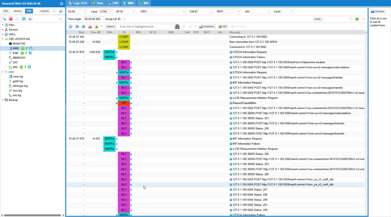
This log sequence shows the full end to end flow of a network initiated 5G NR LPP positioning session for NR eCID.
The procedure starts when the AMF triggers the internal test LMF through the determine-location service. After receiving that request, the LMF prepares the control plane paths it needs. It creates the non UE N2 subscription so that NRPPa messages coming back from the gNB can be forwarded by the AMF. It also creates a UE specific N1/N2 subscription so that UE specific LPP messages and N2 notifications can be correlated to the same positioning session.
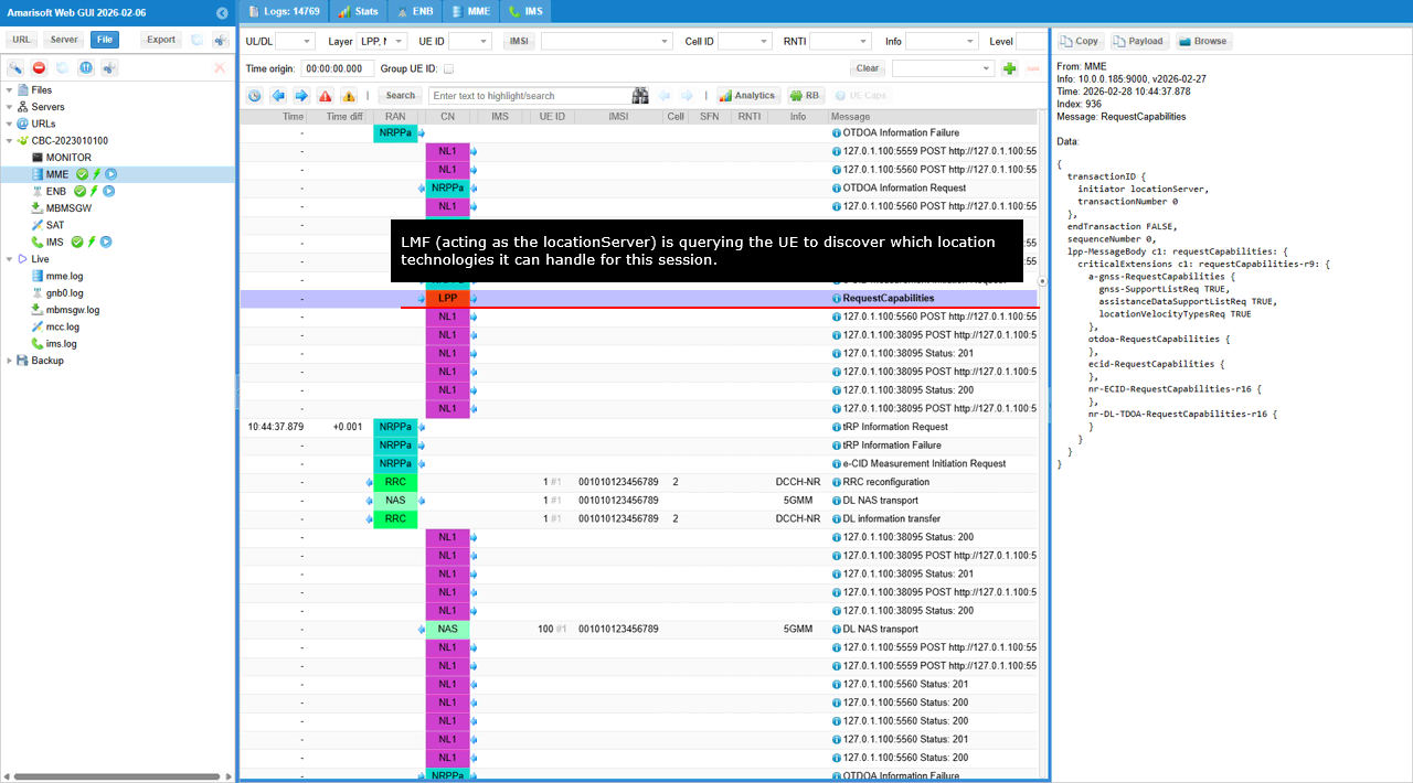
Once the callback paths are ready, the LMF starts the actual positioning procedure in two directions at the same time. Toward the gNB, it sends an NRPPa e-CID Measurement Initiation Request asking for network side eCID measurements such as serving cell information, signal strength and quality, and timing related data. Toward the UE, it sends an LPP RequestCapabilities so the UE can declare which positioning methods and formats it supports.
The UE receives the LPP capability request through NAS carried inside RRC DL Information Transfer. The UE then responds with LPP ProvideCapabilities in UL NAS Transport. In that response, the UE confirms support for A-GNSS, NR eCID, and NR DL-TDOA related capability, including detailed PRS processing capability and reporting support. The network then sends an LPP Ack to confirm it received the capability report correctly.
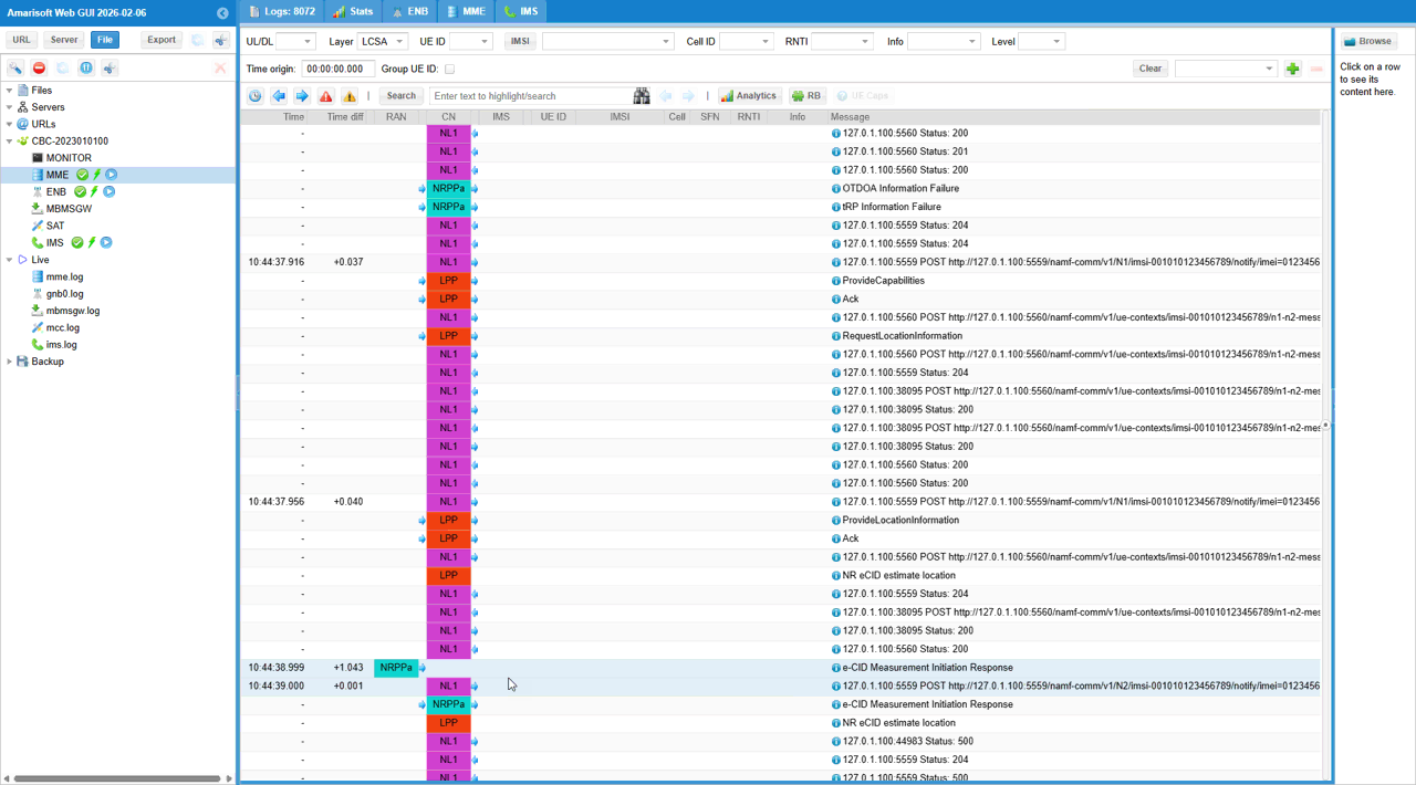
After capability discovery is complete, the LMF sends the real location request to the UE by using LPP RequestLocationInformation. In that request, the LMF asks for a location estimate and includes A-GNSS, NR eCID, and NR DL-TDOA related request elements. The request is targeted to the same UE context through the AMF and is delivered down to the UE again through NAS over RRC.
While that UE side LPP procedure is ongoing, the gNB side also progresses. The gNB sends back the NRPPa e-CID Measurement Initiation Response. That response contains the network side serving cell information, serving cell TAC, access point position of the base station, serving cell RSRP and RSRQ, timing advance related information, and neighbor cell measurement data. The AMF forwards that NRPPa result to the LMF through the previously established N2 notification callback.
On the UE side, the UE answers the RequestLocationInformation with LPP ProvideLocationInformation. In that response, the A-GNSS part reports a location error, meaning the GNSS based estimate did not succeed in this run. However, the NR eCID part succeeds and reports serving cell and neighbor cell measurements. The serving cell is PCI 501 and the neighbor cell is PCI 500, with their corresponding NR RSRP and NR RSRQ values. The network then sends another LPP Ack to acknowledge receipt of this final UE report.
In parallel to the LPP messaging, the normal RRC measurement framework is also active. The UE sends an RRC Measurement Report showing serving and neighbor cell RSRP and RSRQ values. This confirms that the UE measurement configuration installed by RRC Reconfiguration is working and that the radio side measurement path is healthy.
So at a high level, the flow proves that the complete positioning signaling chain is functioning. The AMF, LMF, UE, and gNB all exchange the expected messages. The LPP path between the UE and the LMF works correctly. The NRPPa path between the gNB and the LMF also works and returns network side eCID measurements. The UE fails only on the A-GNSS location estimate, but it successfully provides NR eCID related measurements. The gNB also successfully provides NRPPa eCID measurements. Overall, this is a successful NR eCID signaling session with valid UE side and network side radio measurement exchange, even though the GNSS based part of the requested location information does not succeed in this particular test.
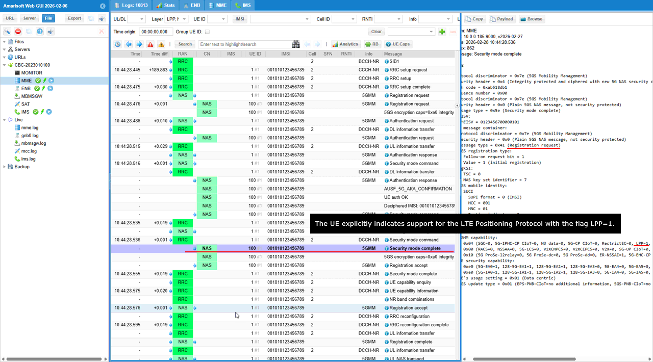
This part shows the UE confirming NAS security and, at the same time, advertising that it supports LPP during registration. The important field to check is 5GMM capability in the Security mode complete. In that capability bitmap, the LPP flag is set to 1. This tells the core network that the UE supports the LTE Positioning Protocol over NAS, so the MME is allowed to start the LPP capability exchange and the later eCID measurement procedure.
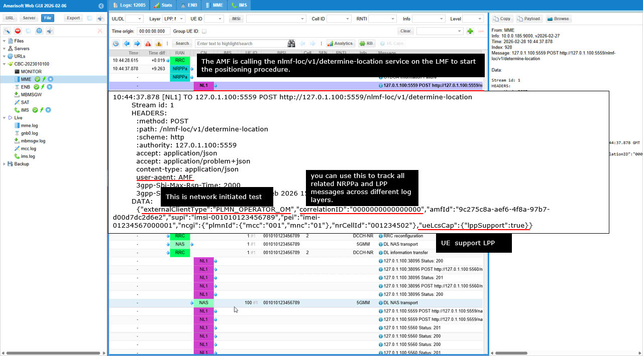
This shows the core network starting the positioning procedure by calling the LMF over the Nlmf_Location service.
The AMF sends an HTTP POST to /nlmf-loc/v1/determine-location. This means the request is network initiated, not UE initiated. The goal is to trigger the LMF to run the location workflow that will later generate NRPPa and LPP messages.
The important tracking field is correlationID in the request data. This value is used to connect all related messages across the AMF, LMF, NRPPa, and LPP logs, so you can follow one positioning session end to end.
The request body also carries the UE identity and serving cell context. supi and pei identify the UE. The ncgi field contains the PLMN and NR cell ID so the LMF knows which RAN node and cell the UE is currently attached to. The ueLocCap section indicates LPP support, so the LMF is allowed to select an LPP based procedure when it proceeds with capability exchange and measurement initiation.
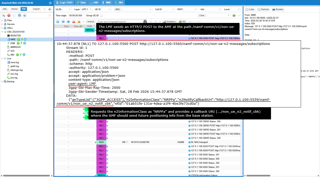
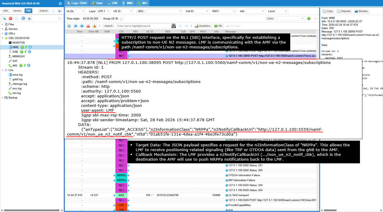
This shows the LMF preparing the control plane path for NRPPa related positioning messages by creating a subscription in the AMF.
The LMF sends an HTTP POST to /namf-comm/v1/non-ue-n2-messages/subscriptions. This tells the AMF that the LMF wants to receive non UE N2 messages that belong to positioning procedures. The key IE is n2InformationClass set to NRPPa. This selects the NRPPa message category so the AMF will route NRPPa transport messages between the LMF side and the RAN side. The other key IE is n2NotifyCallbackUri. This is the callback endpoint where the AMF will deliver future NRPPa related notifications for this positioning session. In this trace it points to the LMF callback path ending with /non_ue_n2_notif_cbk. The request also includes anueList with 3GPP_ACCESS. This scopes the subscription to 3GPP access, which is the normal access type for NR positioning. Finally, nlmfId identifies the LMF instance that owns this subscription, so later notifications can be associated with the correct LMF session.
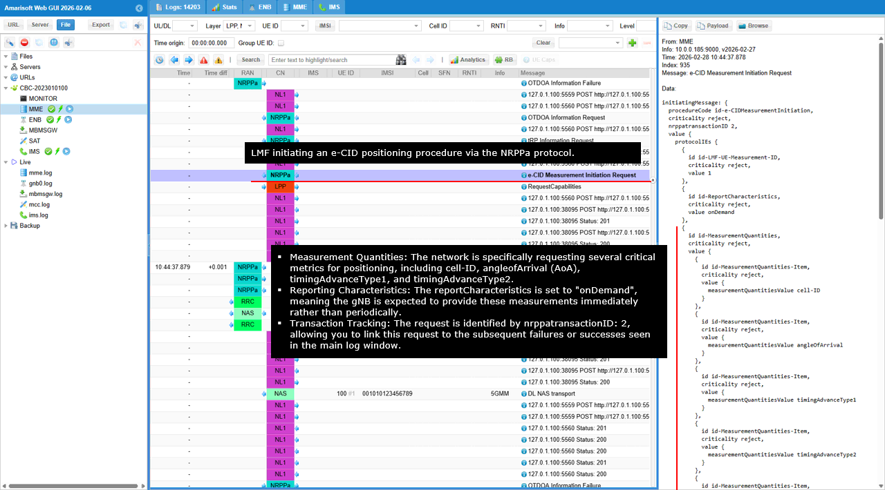
This shows the network starting the NR eCID measurement phase by sending an NRPPa e-CID Measurement Initiation Request from the LMF side toward the RAN.
The key control fields are procedureCode set to e-CIDMeasurementInitiation and nrppaTransactionID set to 2. nrppaTransactionID is the main handle you use to correlate the following NRPPa responses and any failure indications to this specific measurement attempt.
Inside protocolIEs, lMF-UE-Measurement-ID identifies the measurement instance for this UE. reportCharacteristics indicates how the RAN should report the results. In this capture it is onDemand, which means the gNB should provide the requested measurements immediately rather than waiting for periodic reporting.
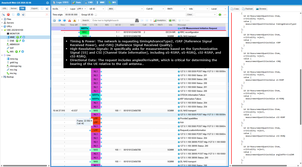
The most important content for what is being measured is measurementQuantities. The request explicitly asks for measurementQuantitiesValue items such as cell-ID, angleOfArrival, timingAdvanceType1, and timingAdvanceType2. These are the core inputs used by the LMF to derive an eCID based location estimate.
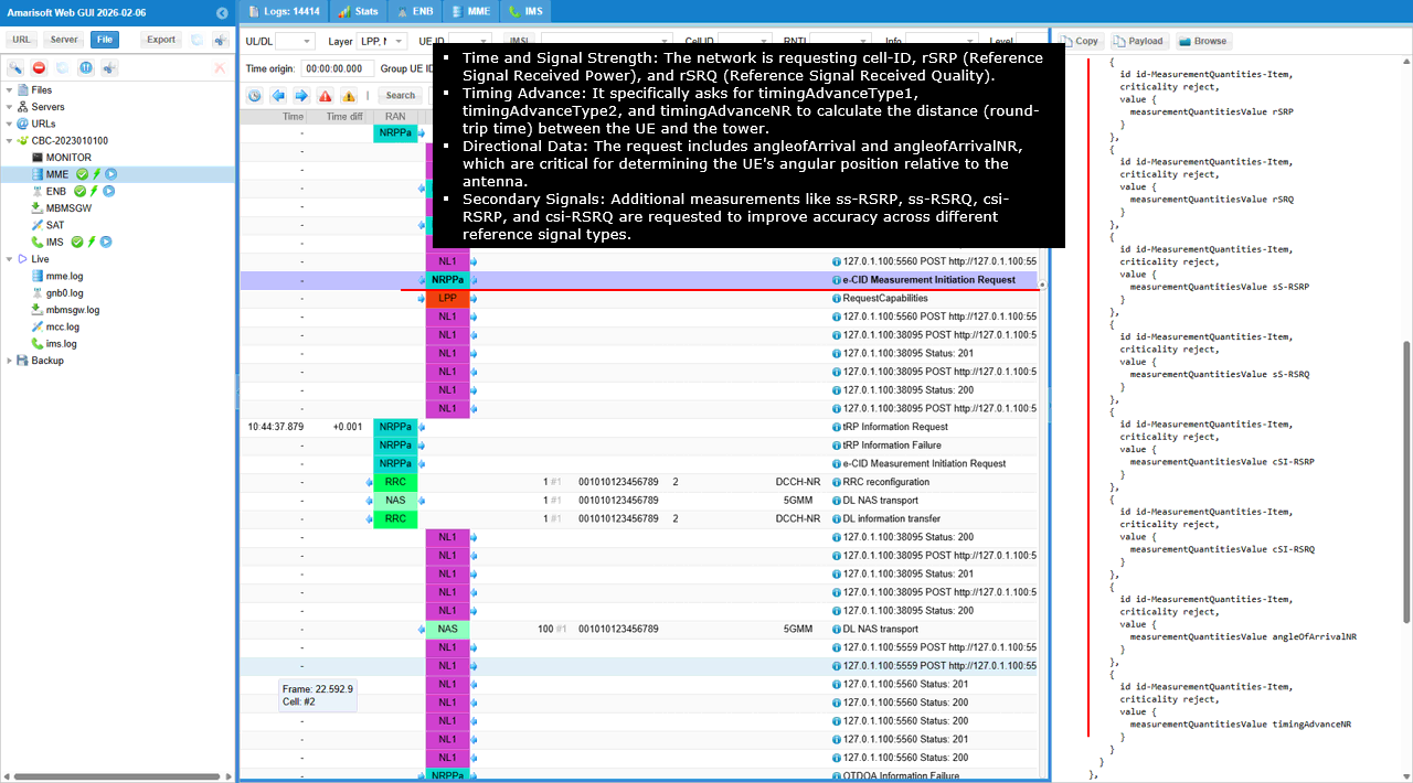
There are also signal strength and quality items : rSRP and rSRQ. These give the serving cell reference signal power and quality. They are used as basic link metrics that help the LMF interpret coverage and confidence.
The request also includes ss-RSRP and ss-RSRQ. These are SSB based measurements, so they reflect the SSB reference signals rather than CSI-RS. This is useful when SSB is the most stable reference in the current configuration.
The request further includes csi-RSRP and csi-RSRQ. These are CSI-RS based measurements, so they provide another reference type that can improve accuracy when CSI-RS is configured and measurable.
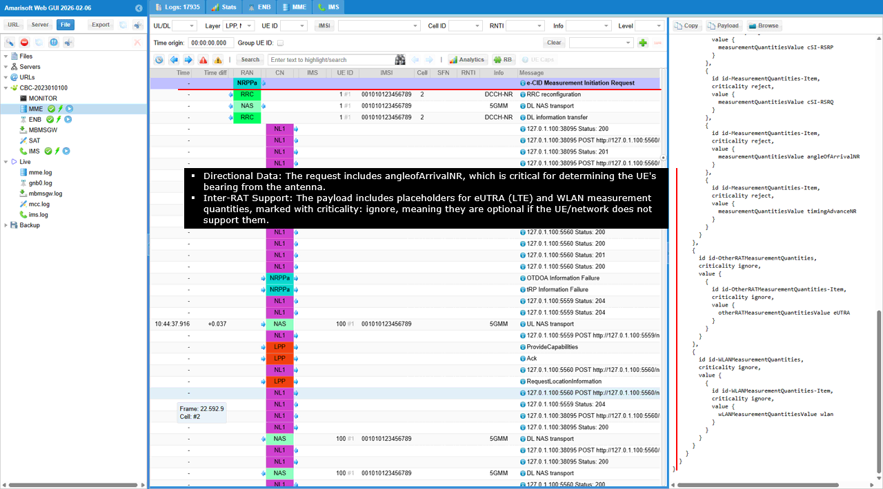
For direction and timing in NR, the decoded list includes angleOfArrivalNR and timingAdvanceNR. angleOfArrivalNR is the angular measurement component, and timingAdvanceNR is the NR timing advance value used as a distance related input in eCID.
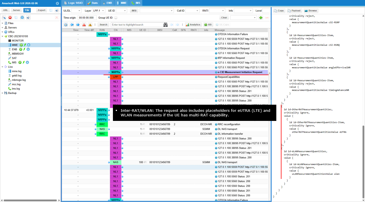
The decoded panel also shows optional cross-technology placeholders. otherRATMeasurementQuantities includes EUTRA, meaning the structure can carry LTE related measurement quantities if the UE supports it. wlanMeasurementQuantities includes wlan, meaning the structure can also carry WLAN related measurement quantities when applicable.
After this message, you should see the gNB provide the requested measurements via the corresponding NRPPa measurement response, using the same nrppaTransactionID and the same lMF-UE-Measurement-ID.
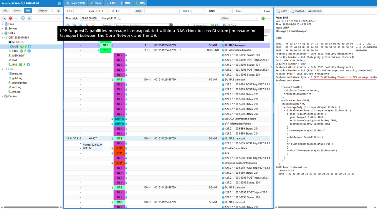
This shows an LPP RequestCapabilities message sent from the network side locationServer to the UE. The key identifier is transactionID with transactionNumber set to 0, which is used to match the UE response to this capability query. endTransaction is FALSE, meaning this is not the final message of the transaction.
The core content is lpp-MessageBody set to requestCapabilities. Under criticalExtensions, requestCapabilities-r9 carries the actual capability request structures. a-gnss-RequestCapabilities is present and it includes assistanceDataSupportListReq set to TRUE. This means the network is asking whether the UE supports A-GNSS and whether it can accept a list of supported GNSS assistance data types. otdoa-RequestCapabilities is included as an empty object. This means the network is querying OTDOA capability without requesting any specific sub-features here. ecid-RequestCapabilities is included as an empty object. This means the network is querying E-CID capability. nr-ECID-RequestCapabilities-r16 is included as an empty object. This explicitly asks for Release 16 NR E-CID capability. nr-DL-TDOA-RequestCapabilities-r16 is included as an empty object. This asks for Release 16 NR DL-TDOA capability.
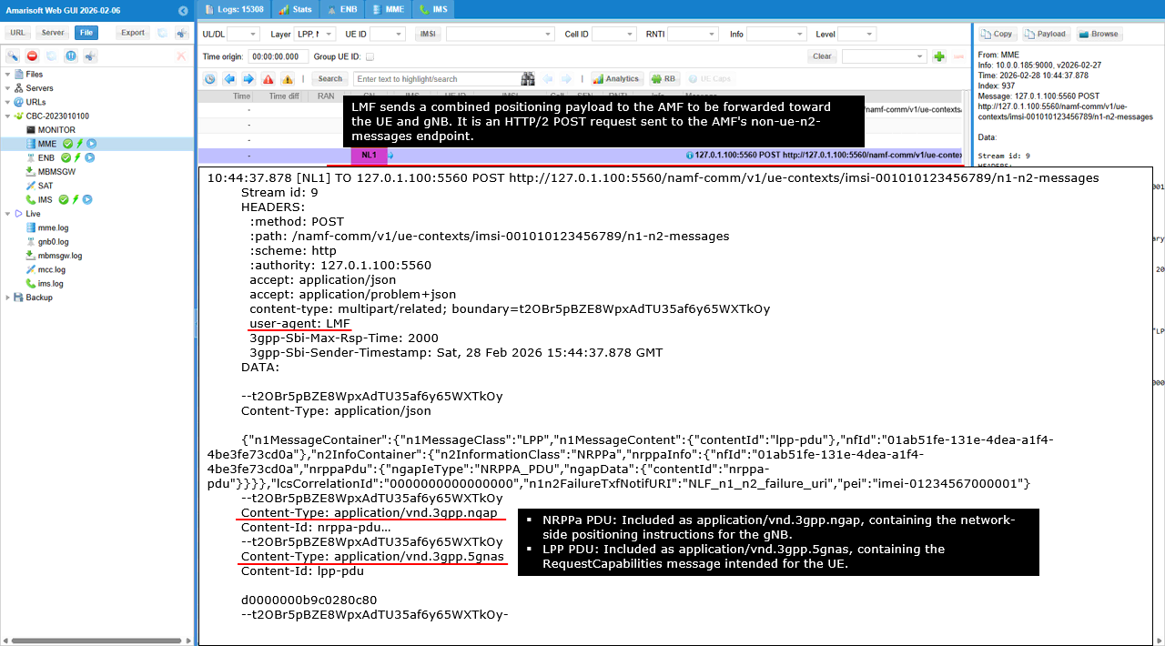
This shows the LMF sending a combined N1 and N2 message package to the AMF so the AMF can forward the positioning signaling to both the UE and the gNB in one coordinated step.
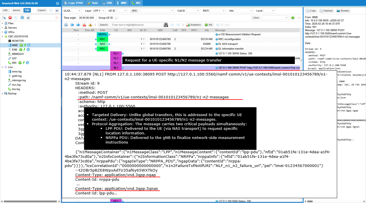
The HTTP POST goes to /namf-comm/v1/ue-contexts/imsi-001010123456789/n1-n2-messages. This endpoint is used when the network needs to deliver an N1 message to the UE and an N2 message to the RAN as part of the same procedure for the same UE context.
The body is multipart/related. The JSON control part defines two containers. n1MessageContainer has n1MessageClass set to LPP and references an LPP PDU by contentId. This is the UE facing positioning message that will be carried over NAS. n2InfoContainer has n2InformationClass set to NRPPa and references an NRPPa PDU by contentId. This is the gNB facing positioning instruction that the AMF will transport on the N2 interface. The two binary parts are then attached by content type. The NRPPa PDU part is carried as application/vnd.3gpp.ngap, which is what the AMF uses to wrap and send the NRPPa payload toward the gNB. The LPP PDU part is carried as application/vnd.3gpp.5gnas, which is what the AMF uses to forward the LPP RequestCapabilities to the UE over NAS.
The key tracking field here is n1n2CorrelationId. This value is used by the AMF to correlate later delivery reports and responses that belong to this combined N1/N2 transmission.
This is the same NRPPa subscription creation step, shown from the AMF side. The AMF log is capturing an incoming HTTP/2 POST from the LMF to the AMF SBI interface at /namf-comm/v1/non-ue-n2-messages/subscriptions.
The key decoded fields are n2InformationClass set to NRPPa and n2NotifyCallbackUri set to the LMF callback endpoint ending with /non_ue_n2_notif_cbk. This tells the AMF to route future non UE N2 NRPPa notifications to that callback.
The payload also includes anTypeList with 3GPP_ACCESS, which scopes the subscription to 3GPP access. nlmfId identifies the LMF instance that owns the subscription so the AMF can associate later notifications with the correct LMF session.
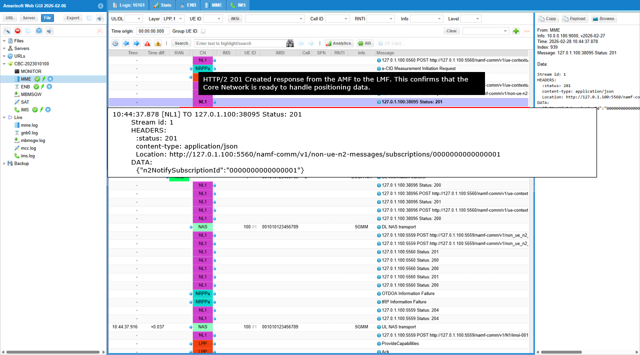
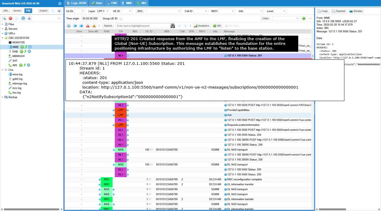
This shows the AMF accepting the NRPPa non UE N2 subscription request and creating a new subscription resource.
The AMF returns HTTP status 201, which means the subscription was successfully created. The Location header contains the newly created resource path under /namf-comm/v1/non-ue-n2-messages/subscriptions/ followed by the subscription identifier.
The response body includes n2NotifySubscriptionId. This is the key value that represents the active subscription. From this point, the AMF can use this subscription to send NRPPa related non UE N2 notifications to the LMF callback URI that was provided in the request.
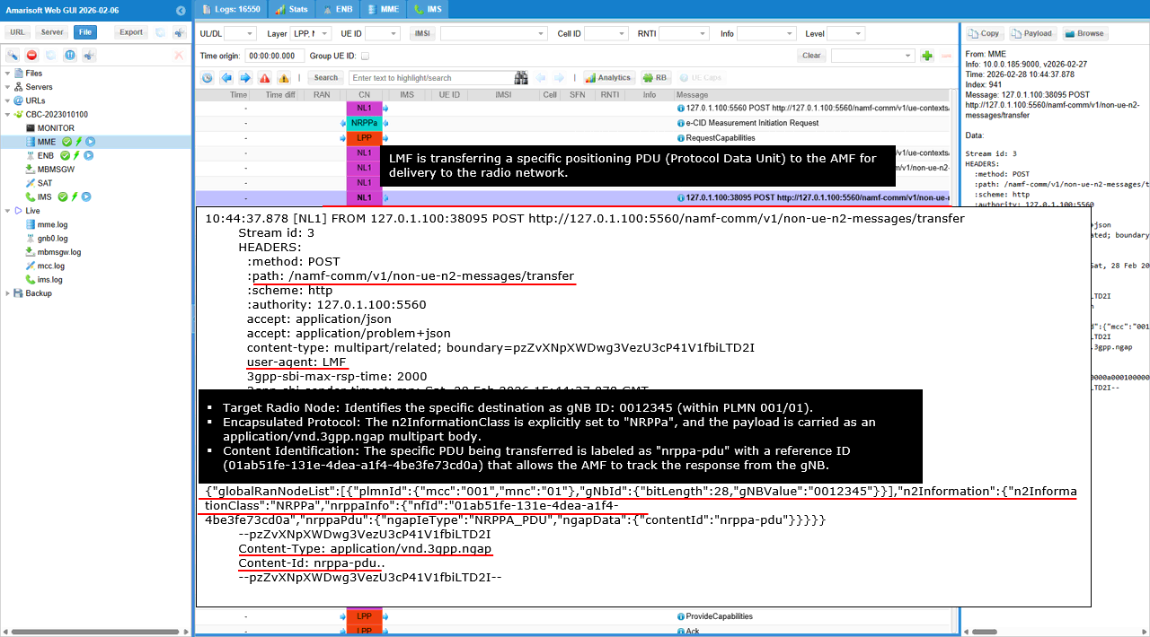
This shows the LMF asking the AMF to transfer a non UE N2 message toward the gNB, specifically an NRPPa PDU carried inside an NGAP container.
The HTTP POST is sent to /namf-comm/v1/non-ue-n2-messages/transfer. This endpoint is used when the LMF wants the AMF to deliver an N2 message to the RAN without involving the UE NAS path.
globalRanNodeList identifies the target RAN node. The important fields are plmnId with mcc 001 and mnc 01, and gnbId with bitLength 28 and gNBValue 0012345. This tells the AMF exactly which gNB should receive the NRPPa message. n2Information shows n2InformationClass set to NRPPa. This selects NRPPa as the protocol carried over N2 for this transfer. nrppaInfo contains nfid, which is the LMF instance identifier used to associate this transfer with the LMF session context. nrppaPdu then defines the payload reference. It states ngapIeType NRPPa_PDU and it points to ngapData with contentId nrppa-pdu. The actual binary part is attached as Content-Type application/vnd.3gpp.ngap with Content-Id nrppa-pdu. This is the NGAP wrapped NRPPa message that the AMF will forward to the gNB.
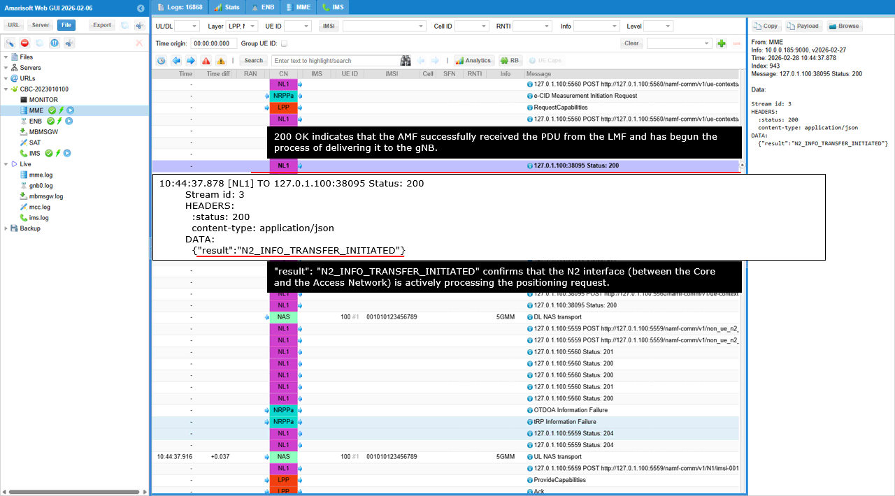
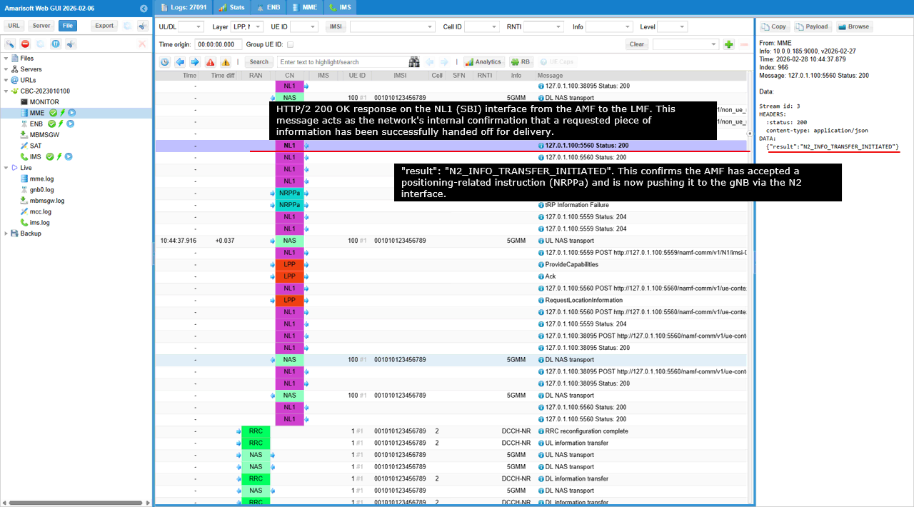
This is the AMF response to the LMF after the non UE N2 transfer request was accepted.
The AMF returns HTTP status 200, meaning the request format and target information were valid and the AMF has taken ownership of delivering the N2 message toward the gNB. The key field is result with the value N2_INFO_TRANSFER_INITIATED. This means the AMF has started the N2 information transfer procedure on the N2 interface. It does not mean the gNB has already responded with measurements yet. It only confirms that the delivery process to the RAN side has been initiated successfully.
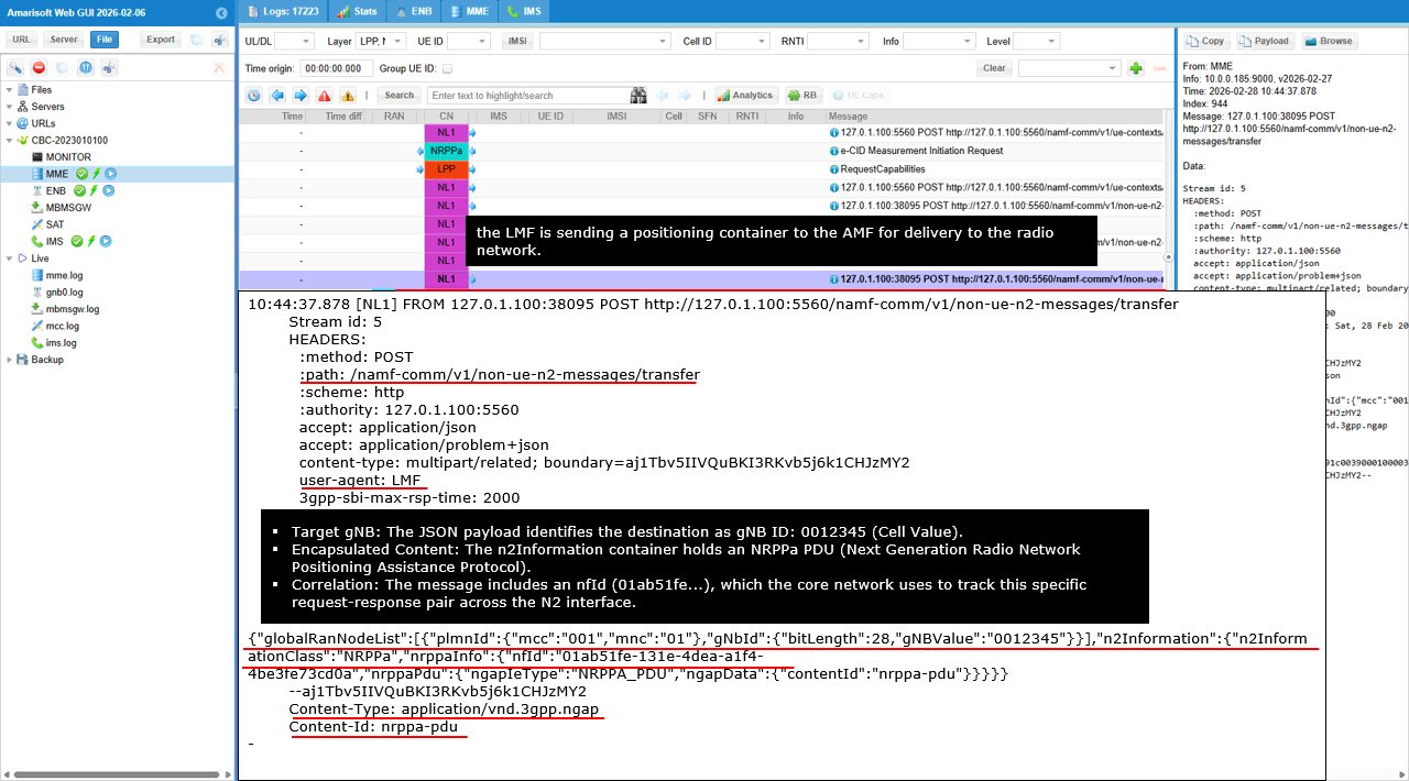
This shows another non UE N2 transfer request from the LMF to the AMF, again using the path /namf-comm/v1/non-ue-n2-messages/transfer. It is the same delivery mechanism used to push an NRPPa message to the gNB over N2.
globalRanNodeList again identifies the target gNB. The key fields are plmnId with mcc 001 and mnc 01, and gnbId with bitLength 28 and gNBValue 0012345. This is the destination RAN node for the positioning message. n2Information sets n2InformationClass to NRPPa, so the AMF treats the attached payload as an NRPPa procedure. nrppaInfo includes nfid, which ties this transfer to the LMF instance and its positioning session context. nrppaPdu declares ngapIeType NRPPa_PDU and points to ngapData using contentId nrppa-pdu. The attached multipart body includes Content-Type application/vnd.3gpp.ngap with Content-Id nrppa-pdu, which is the actual NGAP wrapped NRPPa payload that will be delivered to the gNB.
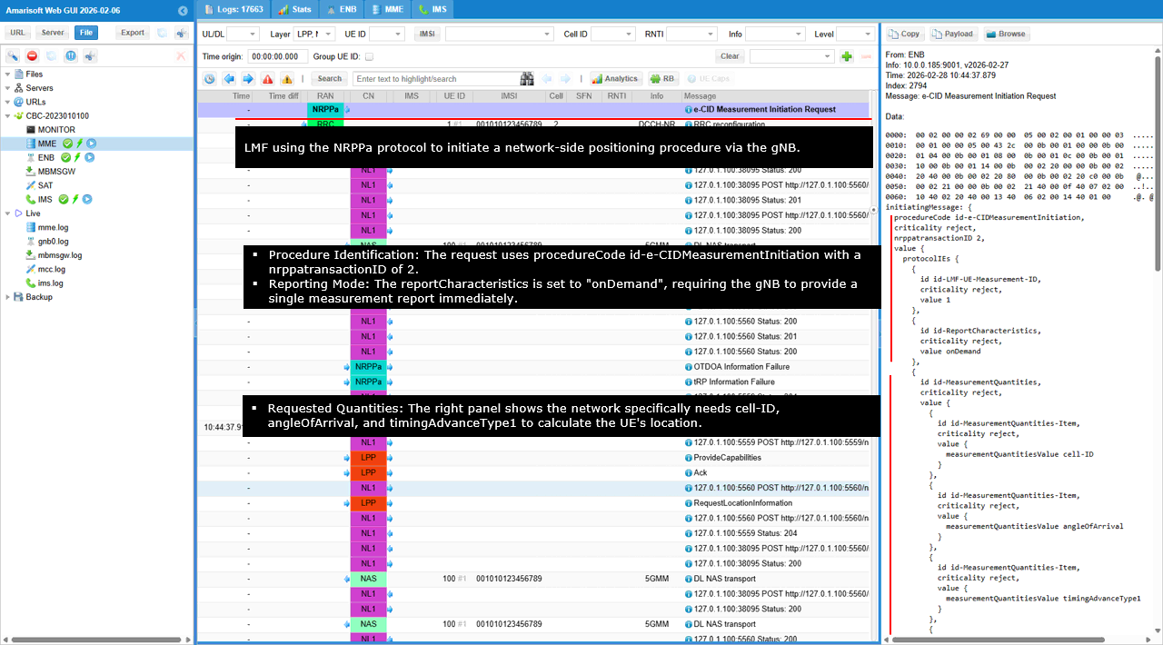
This shows an NRPPa e-CID Measurement Initiation Request being delivered to the gNB. The message is identified by procedureCode set to e-CIDMeasurementInitiation and it uses nrppaTransactionID set to 2, which is the main correlation key for the rest of this measurement exchange.
In the protocolIEs list, lMF-UE-Measurement-ID is present and provides the measurement instance identifier that the gNB should echo back in the response. reportCharacteristics is set to onDemand, which means the gNB should provide an immediate one shot report rather than waiting for a periodic reporting cycle.The measurementQuantities IE lists what the network wants to receive from the gNB for eCID. In this view, the requested items include cell-ID, angleOfArrival, and timingAdvanceType1. These are the core eCID inputs used to identify the serving/neighbor cell context, estimate direction, and estimate range via timing advance.
The request includes timingAdvanceType2. This asks the gNB to provide the second timing advance representation used for positioning. It then requests serving signal metrics rSRP and rSRQ. These are the basic NR reference signal power and quality measurements. It also requests SSB based metrics ss-RSRP and ss-RSRQ. These are useful when SSB is the primary reference signal available for stable measurement. It also requests CSI-RS based metrics csi-RSRP and csi-RSRQ. These provide measurements tied to CSI reference signals when CSI-RS is configured. The request adds NR specific directional and timing items angleOfArrivalNR and timingAdvanceNR, which are the NR oriented versions of the angle and timing advance quantities used in eCID processing. Finally, the message includes optional groups for other technologies. otherRATMeasurementQuantities contains an EUTRA placeholder and wlanMeasurementQuantities contains a wlan placeholder. Both are marked with criticality ignore, meaning the gNB can ignore these parts if they are not supported or not applicable.
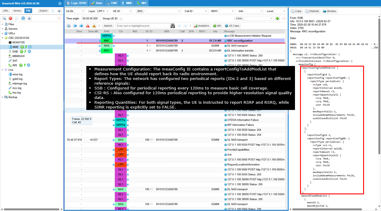
This shows an RRC reconfiguration that installs the measurement configuration the UE will use to provide radio measurements needed by the positioning procedure.
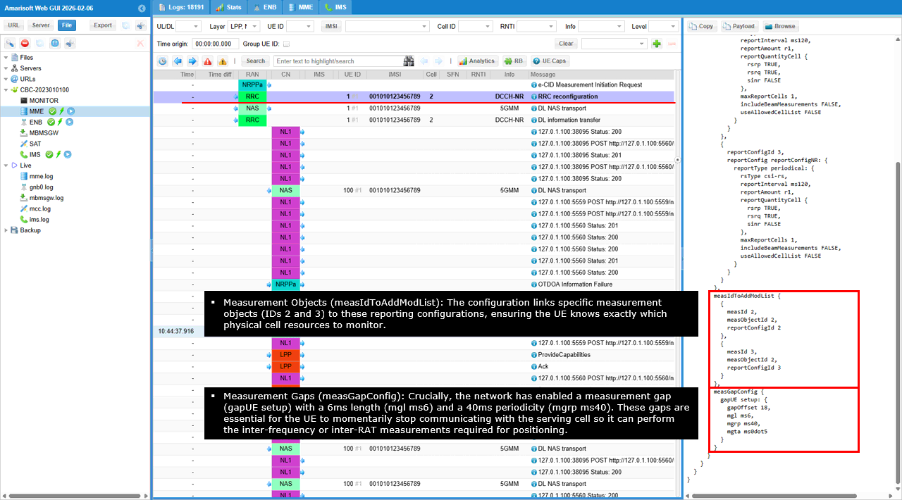
measConfig contains reportConfigToAddModList. Two report configurations are added. reportConfigId 2 and reportConfigId 3 are both periodic reports. reportInterval is ms120 and reportAmount is r1, so the UE is instructed to produce one periodic report at a 120 ms cadence. reportQuantityCell requests rsrp and rsrq, and sinr is set to FALSE. maxReportCells is 1, includeBeamMeasurements is FALSE, and useAllowedCellList is FALSE. measIdToAddModList links measurement IDs to these report configurations. measId 2 points to measObjectId 2 and reportConfigId 2. measId 3 points to measObjectId 2 and reportConfigId 3. This mapping tells the UE which measurement object should be measured and which report rule should be used for each report stream. measGapConfig enables measurement gaps. gapUE is set to setup, with gapOffset 18. mgl is ms6, mgrp is ms40, and mgta is ms0dot5. This configures periodic measurement gaps so the UE can pause normal activity and perform measurements that may require additional RF time, which helps when positioning needs extra measurement opportunities.
This decoded panel shows how the LPP RequestCapabilities is delivered to the UE over NAS.
The key field is payload container type set to 3, which indicates an LPP payload. This tells the UE that the payload container contains an LTE Positioning Protocol message. Inside the payload, the LPP message is RequestCapabilities. transactionID is present with transactionNumber set to 0 and endTransaction set to FALSE, so the UE must respond using the same transactionNumber. In requestCapabilities-r9, a-gnss-RequestCapabilities requests GNSS support and sets assistanceDataSupportListReq to TRUE, meaning the network wants the UE to report which GNSS assistance data types it supports. otdoa-RequestCapabilities and ecid-RequestCapabilities are included to query OTDOA and E-CID capability. The NR extensions nr-ECID-RequestCapabilities-r16 and nr-DL-TDOA-RequestCapabilities-r16 are also present, which asks the UE to declare support for NR eCID and NR DL-TDOA capability in Release 16 terms.
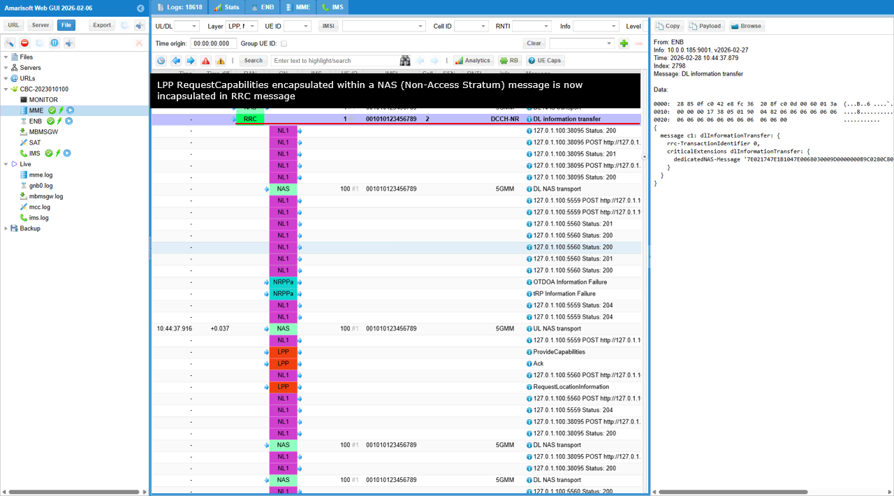
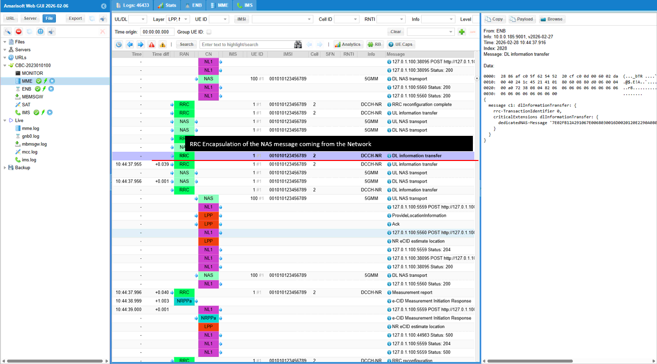
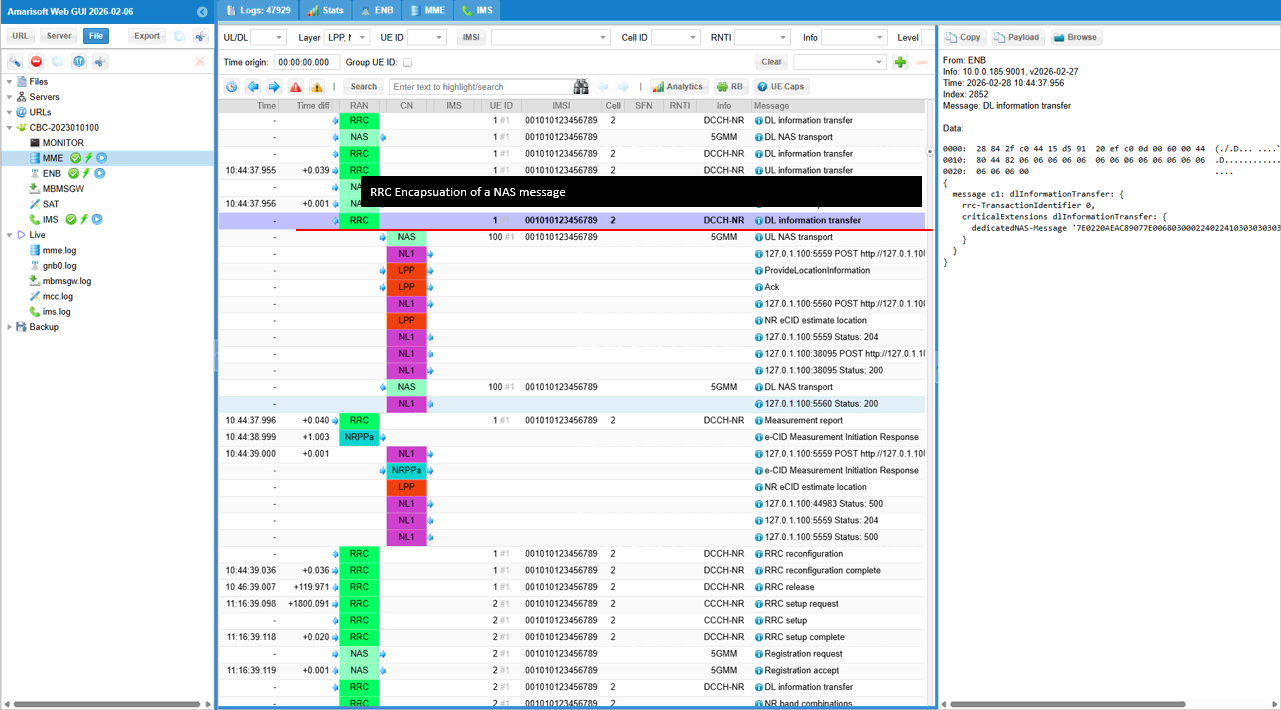
This shows the downlink delivery step on the RRC side after the core network prepared the LPP message. Basically this is the encapsulation of the NAS message shown in previous log.
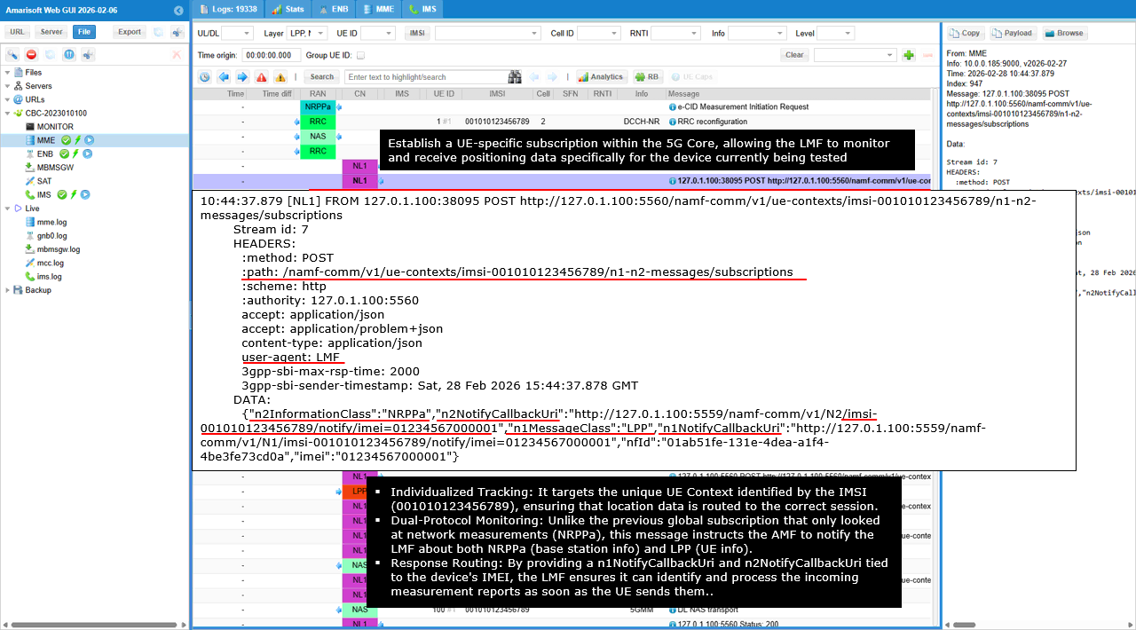
This shows the UE specific subscription setup for combined N1 and N2 positioning related notifications. The LMF sends an HTTP POST to /namf-comm/v1/ue-contexts/imsi-001010123456789/n1-n2-messages/subscriptions. This creates a subscription tied to one UE context, identified by the IMSI in the path.
The key fields are n2InformationClass set to NRPPa and n2NotifyCallbackUri set to an LMF callback URL. This tells the AMF to notify the LMF when NRPPa related N2 events for this UE occur, such as positioning measurement delivery or gNB responses. The request also includes n1MessageClass set to LPP and n1NotifyCallbackUri set to another LMF callback URL. This tells the AMF to notify the LMF when LPP related N1 events for this UE occur, such as UE responses to RequestCapabilities or later LPP messages. The identifiers nfid and imei are included so the subscription can be associated with the correct LMF instance and the correct device identity when notifications arrive. This is important when multiple UEs or multiple parallel positioning sessions are running.
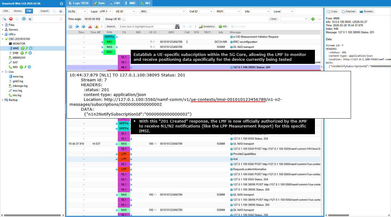
This shows the AMF acknowledging creation of the UE specific N1/N2 subscription. The AMF returns HTTP status 201, which means the subscription resource was successfully created for the UE context identified by the IMSI in the request path.
The Location header provides the resource URI of the new subscription under /namf-comm/v1/ue-contexts/imsi-001010123456789/n1-n2-messages/subscriptions/ followed by the assigned subscription identifier. The response body contains n1n2NotifySubscriptionId. This is the key identifier for the UE specific subscription. The AMF will use this subscription to send both N1 LPP and N2 NRPPa notifications for this UE to the callback URIs that were provided in the subscription request.
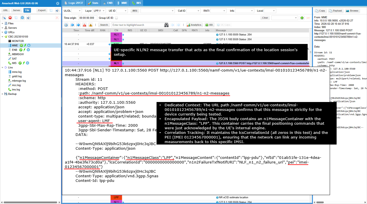
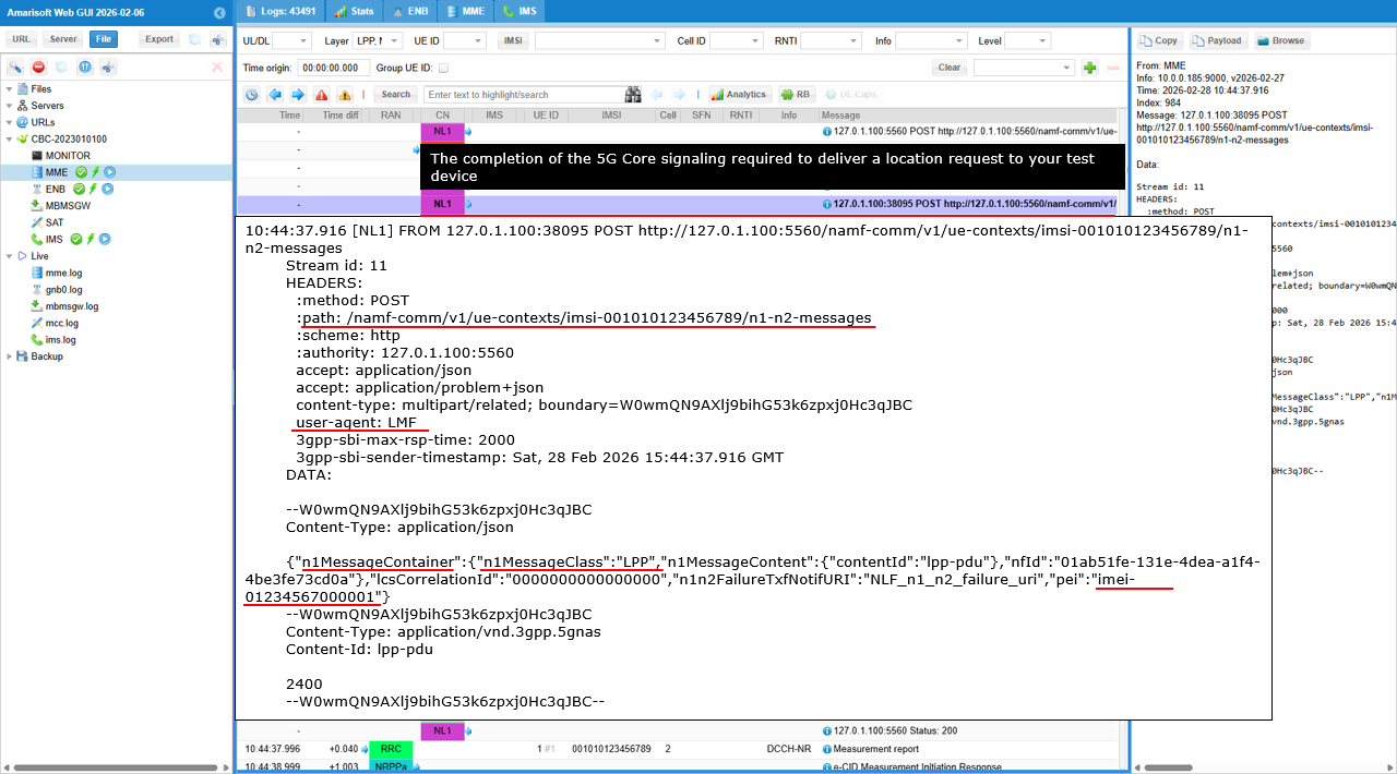
This shows a UE specific combined N1 and N2 message transfer request from the LMF to the AMF. The HTTP POST goes to /namf-comm/v1/ue-contexts/imsi-001010123456789/n1-n2-messages, so the delivery is tied to a single UE context identified by the IMSI in the path.
The JSON part contains n1MessageContainer and n2InfoContainer. n1MessageContainer has n1MessageClass set to LPP and points to an LPP PDU using contentId lpp-pdu. n2InfoContainer has n2InformationClass set to NRPPa and points to an NRPPa PDU using contentId nrppa-pdu. This means the AMF will deliver an LPP message to the UE over NAS and an NRPPa message to the gNB over N2 as part of the same UE specific transaction. nfid is included to associate the transfer with the LMF instance. lcsCorrelationId is included to correlate this combined transfer with the overall positioning procedure. n1n2FailureTxfNotifURI provides the failure notification callback for this transfer. pei carries the device identity so the AMF can match the message to the correct UE equipment record. The multipart parts show the payload types. The NRPPa part is attached as application/vnd.3gpp.ngap with Content-Id nrppa-pdu. The LPP NAS part is attached as application/vnd.3gpp.5gnas with Content-Id lpp-pdu.
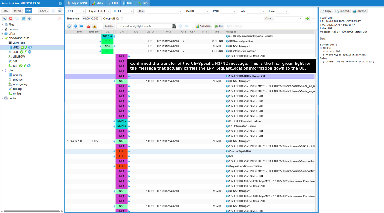
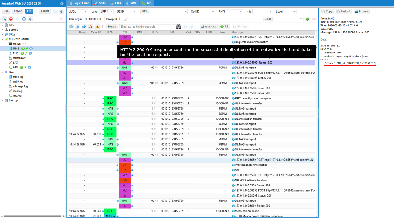
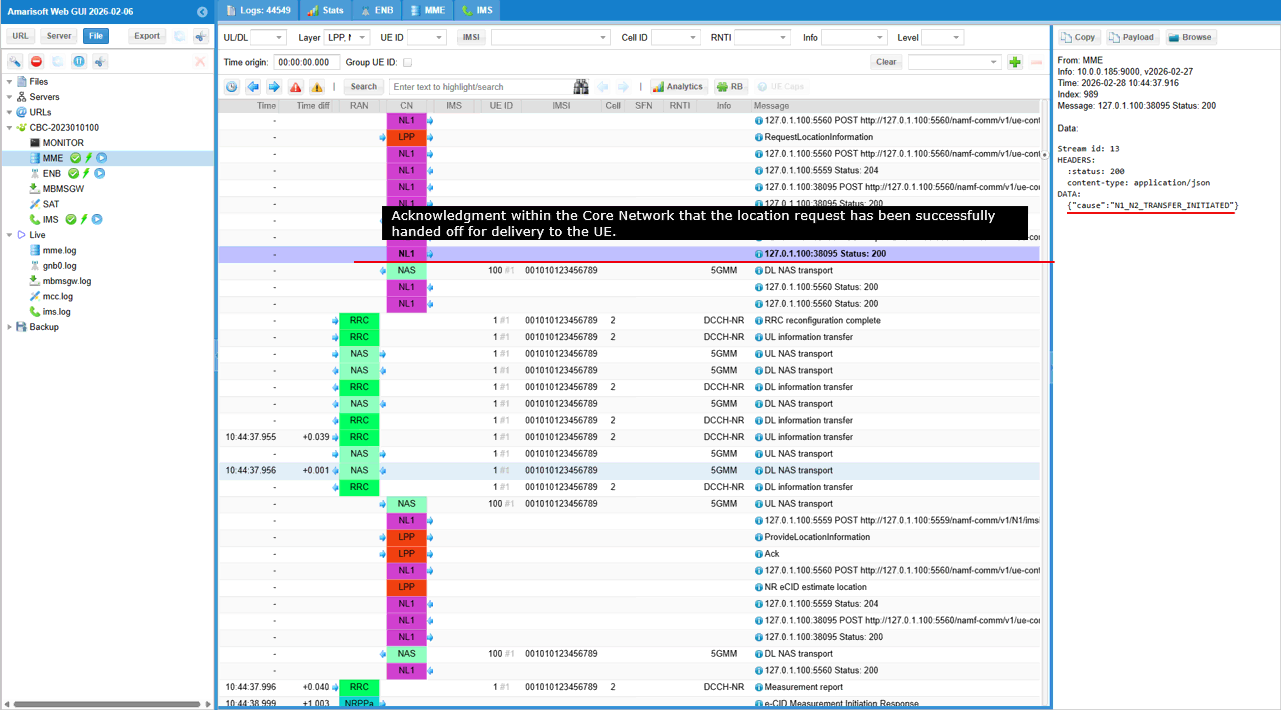
This is the AMF response to the UE specific N1/N2 message transfer request. The AMF returns HTTP status 200, meaning the combined N1/N2 transfer request was accepted and is being processed. The key field is cause with the value N1_N2_TRANSFER_INITIATED. This indicates the AMF has started delivering the N1 message toward the UE and the N2 message toward the gNB for this UE context. It confirms initiation of delivery, not the final delivery result or any UE or gNB response yet.
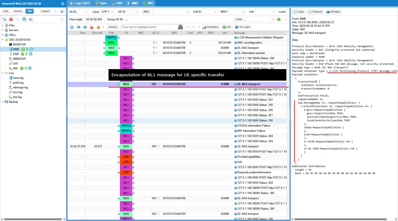
This shows the UE facing N1 delivery part of the UE specific N1/N2 transfer. The AMF has wrapped the LPP message into a downlink NAS transport so it can be delivered to the UE.
The outer NAS message is DL NAS transport with protocol discriminator 5GMM and a security header indicating the message is integrity protected and ciphered. This confirms the LPP signaling is being sent under the active NAS security context.
The key field is payload container type set to 3, which indicates the payload is an LPP message. The payload itself is an LPP RequestCapabilities. It carries transactionID with transactionNumber 0 and endTransaction FALSE, so the UE must answer with ProvideCapabilities using the same transactionNumber. Inside requestCapabilities-r9, the network is querying a-gnss-RequestCapabilities with assistanceDataSupportListReq TRUE and also includes otdoa-RequestCapabilities and ecid-RequestCapabilities. The NR extensions nr-ECID-RequestCapabilities-r16 and nr-DL-TDOA-RequestCapabilities-r16 are also present, so the UE is asked to declare NR eCID and NR DL-TDOA capability support as well.
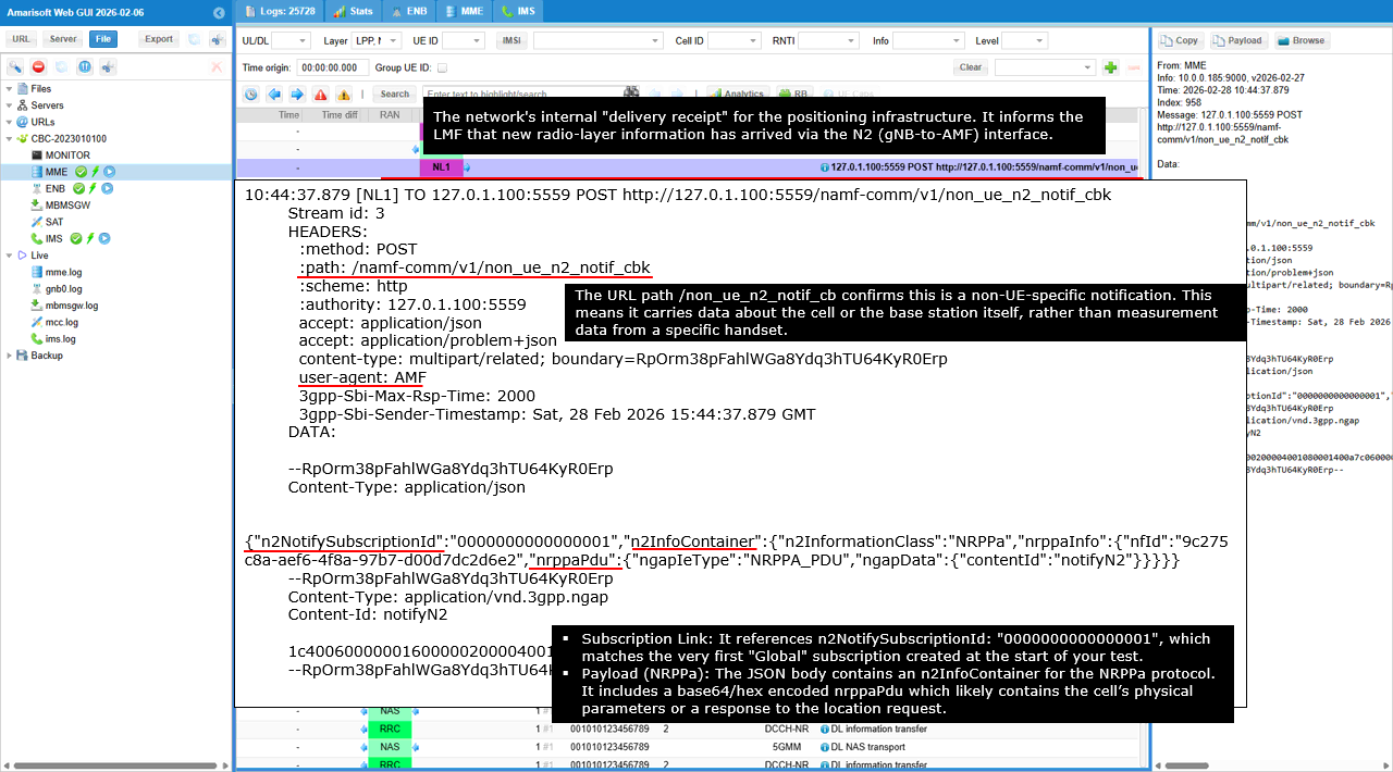
This shows an AMF notification delivered to the LMF callback for the non UE N2 subscription.
The HTTP POST goes to /namf-comm/v1/non_ue_n2_notif_cbk, which is the callback URI the LMF previously registered in the global non UE N2 subscription. The key field that ties it back to that subscription is n2NotifySubscriptionId, which matches the global subscription ID created earlier.
The notification body carries n2InfoContainer with n2InformationClass set to NRPPa. This tells the LMF that the attached payload is an NRPPa related N2 notification coming from the RAN side. Inside nrppaInfo, nfid identifies the LMF instance context, and nrppaPdu points to an attached NGAP part using contentId notifyN2. The multipart attachment is Content-Type application/vnd.3gpp.ngap with Content-Id notifyN2. This NGAP wrapped NRPPa payload is the actual radio side response or indication that the AMF is forwarding to the LMF as part of the positioning procedure.
This is the AMF response confirming creation of the global non UE N2 subscription that the LMF requested earlier.
The AMF returns HTTP status 201, meaning the subscription resource was successfully created. The Location header gives the URI of the created resource under /namf-comm/v1/non-ue-n2-messages/subscriptions/ followed by the subscription identifier. The response body contains n2NotifySubscriptionId set to 0000000000000001. This ID is the handle for the global subscription. The AMF will use this subscription to send future NRPPa non UE N2 notifications to the LMF callback URI that was registered in the subscription request.
This is the AMF response to the non UE N2 transfer request.
The AMF returns HTTP status 200, meaning the request was accepted and processed at the SBI layer. The response body contains result set to N2_INFO_TRANSFER_INITIATED. This indicates the AMF has started the N2 information transfer procedure toward the gNB for the attached NRPPa payload. It confirms initiation of delivery on N2, not the completion of delivery and not the measurement result itself.
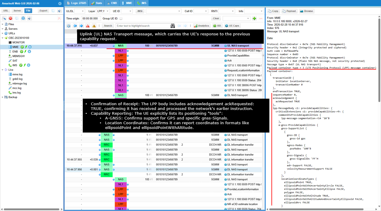
This shows the UE response to the earlier LPP RequestCapabilities, carried in an uplink UL NAS transport.
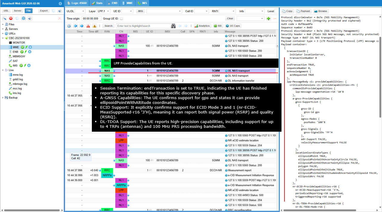
The outer NAS message is UL NAS transport in 5GMM with security header showing integrity protection and ciphering. payload container type is 3, so the payload is an LPP message. The LPP payload is provideCapabilities. transactionID matches the earlier request with transactionNumber 0, and endTransaction is TRUE, meaning the capability exchange is complete for this transaction. The acknowledgement section includes ackRequested TRUE, which confirms the UE recognized the request and is asking for an acknowledgement behavior as defined by LPP.
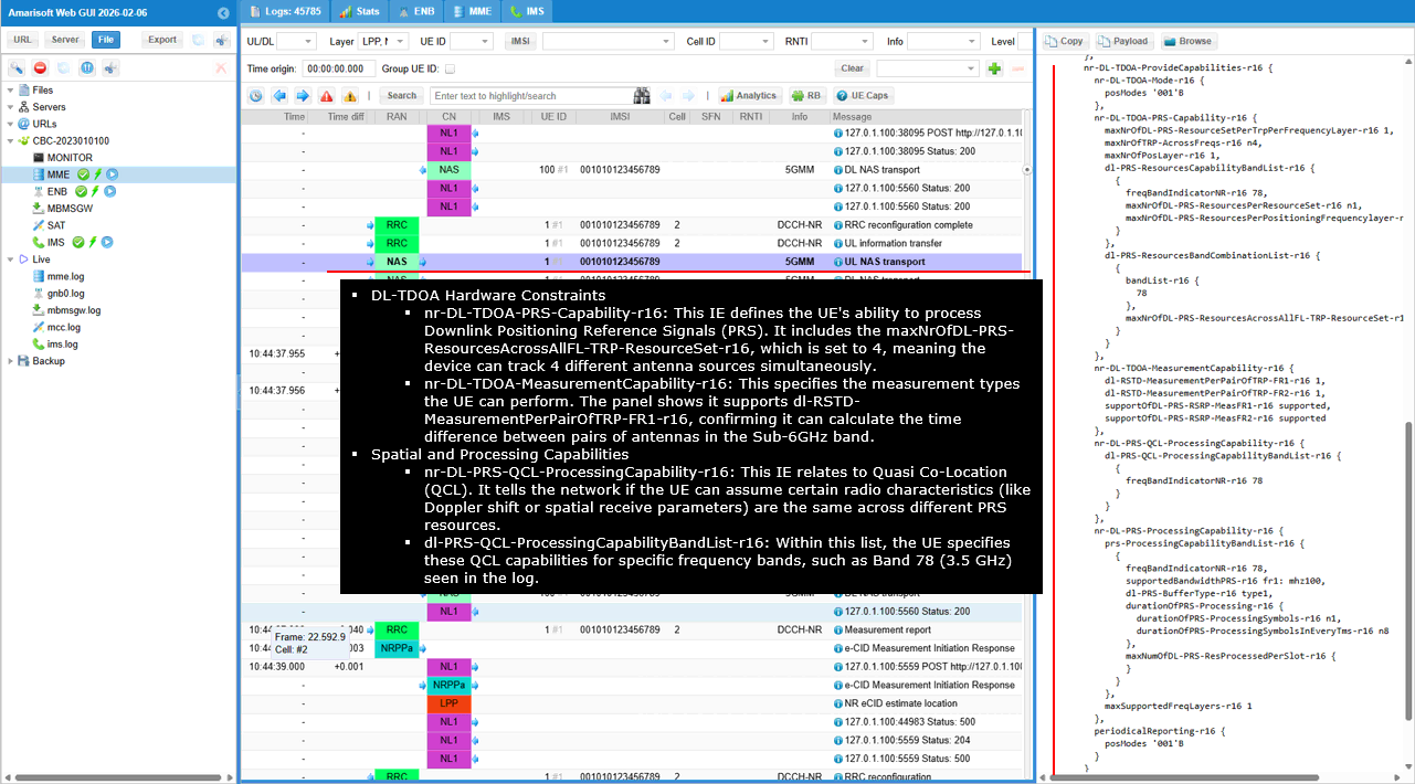
In provideCapabilities-r9, the decoded content lists what the UE can support. It includes a-gnss-ProvideCapabilities with gnss-SupportList and gnss-IDs, plus gnss-Modes. It also lists locationCoordinateTypes, indicating which coordinate formats the UE can report, such as ellipsoidPoint and ellipsoidPointWithAltitude. The decoded panel also contains Release 16 NR capability blocks. nr-ECID-ProvideCapabilities-r16 indicates the UE supports NR eCID measurement reporting, including periodic and triggered reporting capability. nr-DL-TDOA-ProvideCapabilities-r16 indicates NR DL-TDOA related capability, and it includes detailed PRS related capability groups. Within the NR DL-TDOA PRS capability details, the decoded panel shows limits like maxNrofDL-PRS-ResourceSetPerTRPPerFrequencyLayer and maxNrofTRP-AcrossFreqs, and it lists supported bands in dl-PRS-ResourcesBandCombinationList-r16 with bandList-r16 including band 78. It also shows measurement and processing capability items such as dl-RSTD-MeasurementPerPairOfTRP-FR1-r16, supportOfDL-PRS-RSRP-MeasFR1-r16, and processing related items in nr-DL-PRS-QCL-ProcessingCapability-r16 and nr-DL-PRS-ProcessingCapability-r16, including buffer type and processing duration parameters.
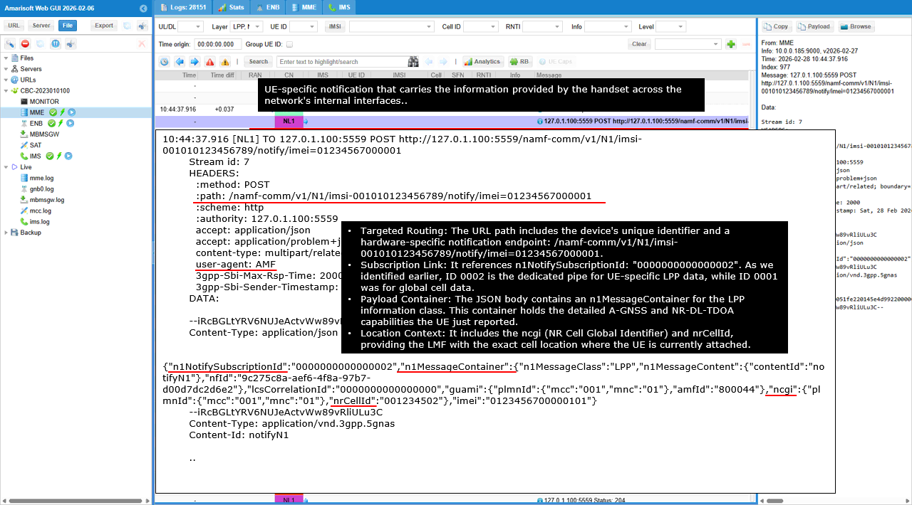
This decoded panel shows a UE specific N1 notification being pushed from the AMF to the LMF callback.
The HTTP POST goes to /namf-comm/v1/N1/imsi-001010123456789/notify/imei=012345670000001. This path indicates it is an N1 side notification tied to a specific UE context (IMSI) and device identity (IMEI), using the callback URI that was registered in the UE specific N1/N2 subscription. The key correlation field is n1NotifySubscriptionId. It is set to 0000000000000002, which matches the UE specific subscription that the AMF created earlier. This tells the LMF that this notification belongs to that UE specific N1 subscription, not the global non UE subscription.
The JSON body includes n1MessageContainer with n1MessageClass set to LPP. This means the attached payload is an LPP message coming from the UE. n1MessageContent points to a multipart attachment using contentId notifyN1. The attached part has Content-Type application/vnd.3gpp.5gnas and Content-Id notifyN1. This attachment is the actual NAS container carrying the UE generated LPP ProvideCapabilities message. The notification also carries context fields like nfid to associate it with the LMF instance, lcsCorrelationId to correlate with the overall positioning procedure, and radio context such as ncgi and nrCellId so the LMF knows which serving cell the UE was attached to when the capability information was reported.
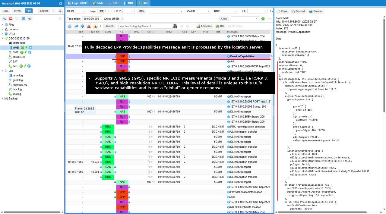
This shows the LPP ProvideCapabilities message after it has been fully decoded by the network location side.
transactionID shows transactionNumber 0 and endTransaction TRUE, confirming it is the UE response that closes the earlier RequestCapabilities transaction. acknowledgement shows ackRequested TRUE, indicating the UE is requesting the acknowledgement behavior defined in LPP. The main content is provideCapabilities-r9. commonIEsProvideCapabilities includes lpp-message-segmentation-r14, indicating the UE supports LPP message segmentation. a-gnss-ProvideCapabilities shows gnss-SupportList with gnss-Id set to gps and gnss-Signals indicating the supported GPS signals. agnss-Modes is present with posModes. adr-Support and velocityMeasurementSupport are FALSE. locationCoordinateTypes lists which coordinate formats the UE can report. ellipsoidPoint is TRUE and ellipsoidPointWithAltitude is TRUE, while other formats like uncertainty circle and ellipse types are FALSE. nr-ECID-ProvideCapabilities-r16 indicates NR eCID support. It shows nr-ECID-MeasSupported-r16 and reporting support flags including periodicalReporting-r16 supported and triggeredReporting-r16 supported. nr-DL-TDOA-ProvideCapabilities-r16 indicates NR DL-TDOA related capability. nr-DL-TDOA-Mode-r16 is present with posModes, showing the UE supports the NR DL-TDOA positioning mode category that the network queried.
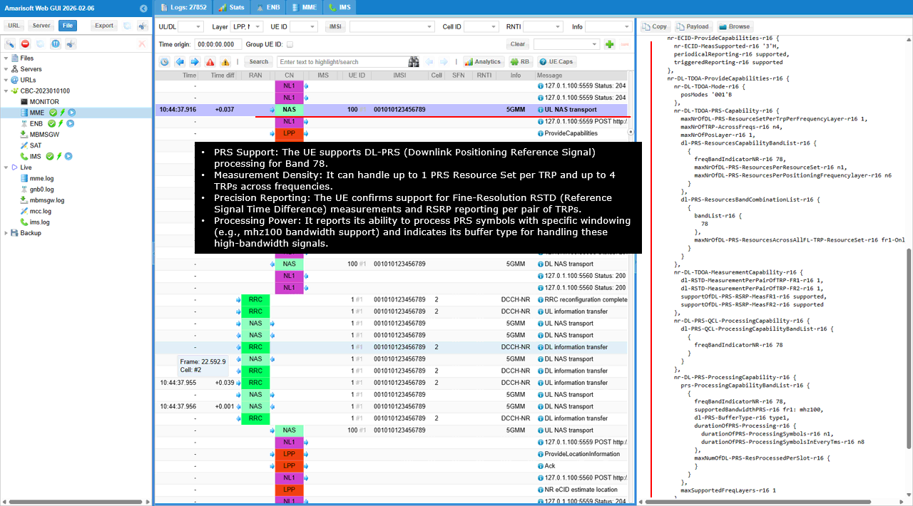
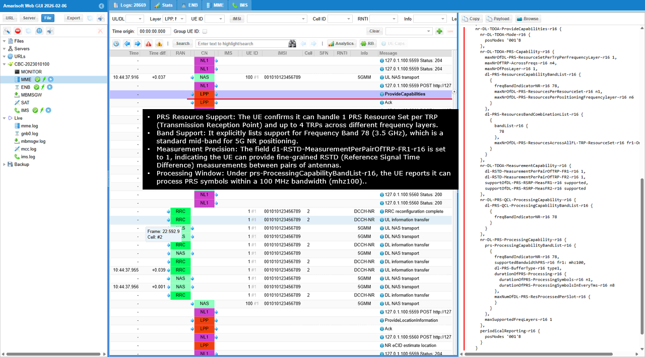
nr-DL-TDOA-PRS-Capability-r16 reports the UE limits for PRS resource handling. maxNrofDL-PRS-ResourceSetPerTRPPerFrequencyLayer-r16 is 1, meaning the UE can handle one PRS resource set per TRP per frequency layer. maxNrofTRP-AcrossFreqs-r16 is 4, meaning it can handle up to four TRPs across frequency layers. maxNrofPosLayers-r16 is 1, meaning one positioning frequency layer is supported. dl-PRS-ResourcesCapabilityBandList-r16 and dl-PRS-ResourcesBandCombinationList-r16 show band support. freqBandIndicatorNR-r16 and bandList-r16 indicate band 78 is supported for PRS based positioning. nr-DL-TDOA-MeasurementCapability-r16 shows measurement support for RSTD and PRS RSRP. dl-RSTD-MeasurementPerPairOfTRP-FR1-r16 is 1 and dl-RSTD-MeasurementPerPairOfTRP-FR2-r16 is 1, indicating the UE can measure RSTD per TRP pair in both FR1 and FR2. supportOfDL-PRS-RSRP-MeasFR1-r16 is supported and supportOfDL-PRS-RSRP-MeasFR2-r16 is supported, indicating PRS RSRP measurement support for both ranges.
nr-DL-PRS-QCL-ProcessingCapability-r16 provides the QCL processing capability band list and again indicates freqBandIndicatorNR-r16 is 78. nr-DL-PRS-ProcessingCapability-r16 reports PRS processing constraints. supportBandIndicatorNR-r16 is 78. dl-PRS-BufferType-r16 is type1, which describes the buffering model the UE uses for PRS processing. durationOfPRS-Processing-r16 is n1 and durationOfPRS-ProcessingSymbols-r16 is n1, indicating minimal stated processing duration. durationOfPRS-ProcessingSymbolsInEveryTms-r16 is n8, indicating the UE can process up to that number of PRS symbols per millisecond window. maxNumOfDL-PRS-ProcessedPerSlot-r16 is 6, indicating the UE can process up to six PRS resources per slot. maxSupportedFreqLayers-r16 is 1, confirming single frequency layer support. periodicalReporting-r16 is present with posModes, indicating the UE can do periodic reporting for these NR positioning measurements.
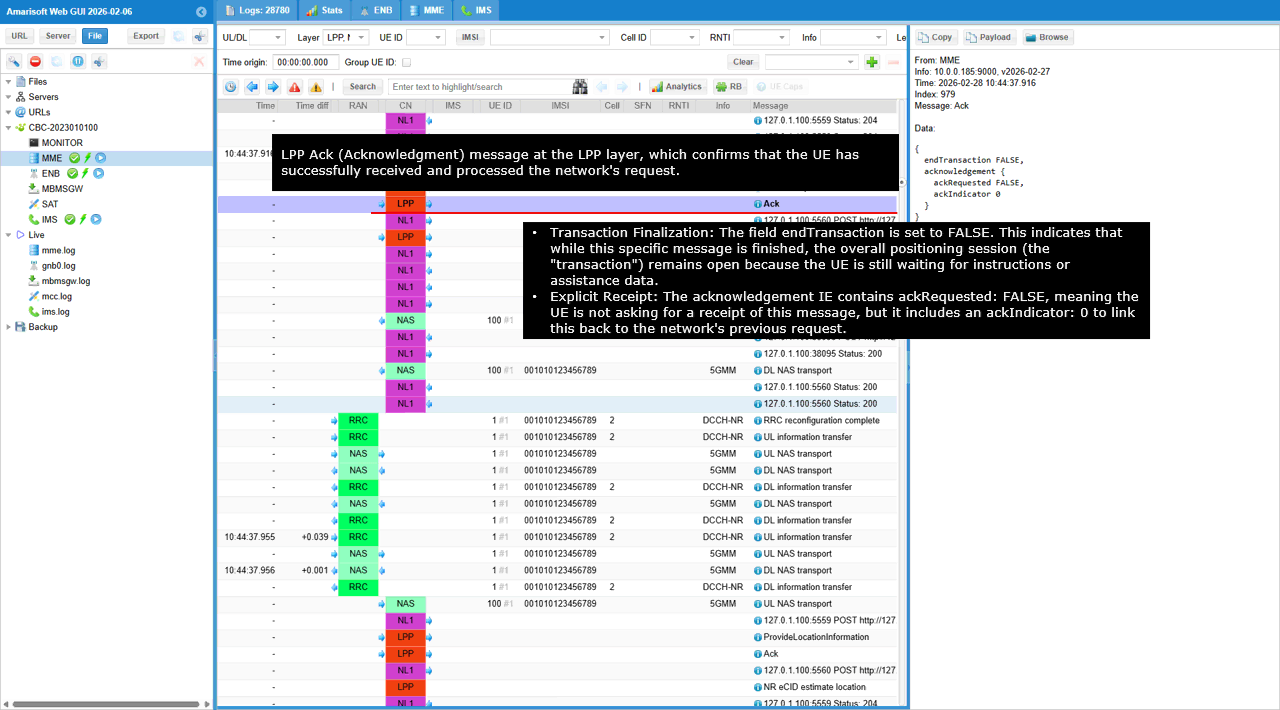
This shows an LPP Ack message handled on the network side after the capability exchange.
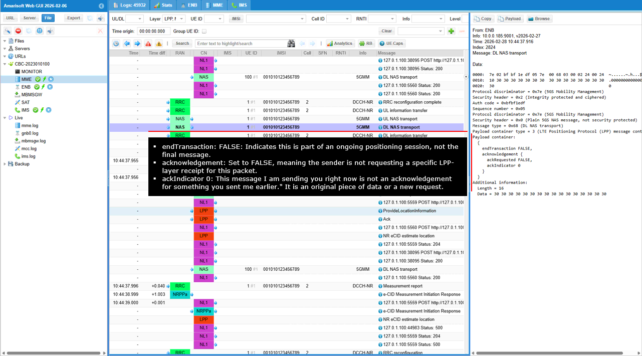
The message type is Ack and it contains an acknowledgement container. ackRequested is FALSE, meaning this Ack does not request a further acknowledgement in return. ackIndicator is 0, which is the value used to relate this Ack to the previously received LPP message in the same flow. endTransaction is FALSE, which means the overall LPP transaction context remains open for the next positioning messages, such as RequestLocationInformation and later measurement reporting.
This shows another UE specific N1/N2 message transfer request from the LMF to the AMF, but in this case it carries only an N1 LPP payload.
The HTTP POST goes to /namf-comm/v1/ue-contexts/imsi-001010123456789/n1-n2-messages, so it is explicitly tied to the UE context identified by that IMSI. The JSON body contains n1MessageContainer with n1MessageClass set to LPP. n1MessageContent points to contentId lpp-pdu, and the multipart attachment includes Content-Type application/vnd.3gpp.5gnas with Content-Id lpp-pdu. This means the AMF will deliver an LPP message to the UE over NAS, without an accompanying NRPPa N2 payload in this transfer. nfid ties the request to the LMF instance. lcsCorrelationId is present as the session correlation tag used across the positioning flow. n1n2FailureTxfNotifURI provides the failure notification callback for this transfer. pei carries the device identity so the AMF can bind the message to the correct UE equipment record during delivery.
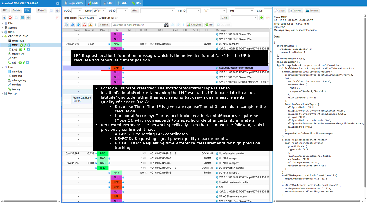
The shows an LPP RequestLocationInformation message sent by the locationServer to start the actual positioning measurement and reporting phase.
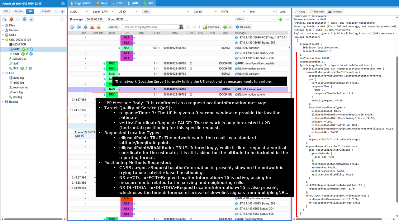
transactionID is present with transactionNumber 1. endTransaction is FALSE, so this request opens a new transaction that will be completed by the UE response. In requestLocationInformation-r9, locationInformationType is set to locationEstimatePreferred. This means the network is asking for a position estimate result rather than only raw measurement data. qos is present with responseTime set to 3, so the UE is expected to deliver the result within about 3 seconds. verticalCoordinateRequest is FALSE, so altitude is not requested. responseTimeEarlyFix-r12 is 1, which indicates the network also allows an early fix behavior. velocityRequest is FALSE, so the UE is not asked to report velocity. locationCoordinateTypes indicates which coordinate formats are acceptable. ellipsoidPoint is TRUE and ellipsoidPointWithAltitude is TRUE, while the other uncertainty ellipse and polygon formats are FALSE. This tells the UE what output formats the server can accept for the location estimate. segmentationInfo-r14 is set to noMoreMessages, meaning message segmentation is not being used for this request. a-gnss-RequestLocationInformation contains the positioningInstructions and gnss-Method with gnss-id. fineTimeAssistanceMeasReq is FALSE, adrMeasReq is FALSE, multipleFreqMeasReq is FALSE, and assistanceAvailability is FALSE. This means the request is using a minimal A-GNSS method request without additional fine time or multi frequency measurement assistance. nr-ECID-RequestLocationInformation-r16 is included, indicating the procedure should also use NR eCID related information for the location estimate. nr-DL-TDOA-RequestLocationInformation-r16 is included. It shows nr-RequestedMeasurements with nr-RequestedMeasurements-r16 and nr-AssistanceAvailability-r16 FALSE, meaning the network is requesting NR DL-TDOA related measurements but is not indicating that assistance data is available in this step.
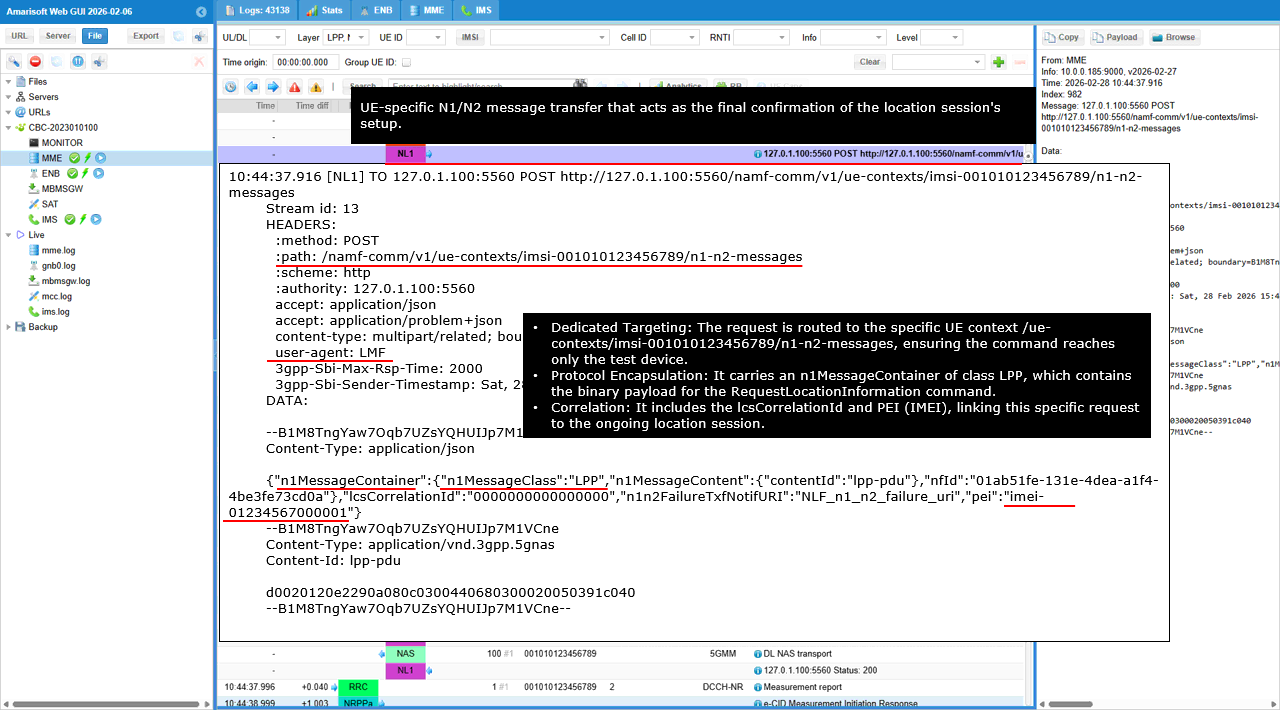
This shows the SBI request that actually delivers the LPP RequestLocationInformation to the UE, using a UE specific N1/N2 message transfer.
The HTTP POST goes to /namf-comm/v1/ue-contexts/imsi-001010123456789/n1-n2-messages. Because the IMSI is in the path, the request is bound to that single UE context. The payload is multipart/related. The JSON part contains n1MessageContainer with n1MessageClass set to LPP and n1MessageContent pointing to contentId lpp-pdu. This tells the AMF the message is an N1 LPP payload to be sent to the UE. The attached part has Content-Type application/vnd.3gpp.5gnas with Content-Id lpp-pdu. This is the NAS container that carries the LPP RequestLocationInformation message. The request also includes nfid to identify the LMF instance, lcsCorrelationId to correlate this delivery with the ongoing positioning session, n1n2FailureTxfNotifURI to specify where the AMF should report delivery failures, and pei with the UE IMEI so the AMF can associate the transfer with the correct device identity.
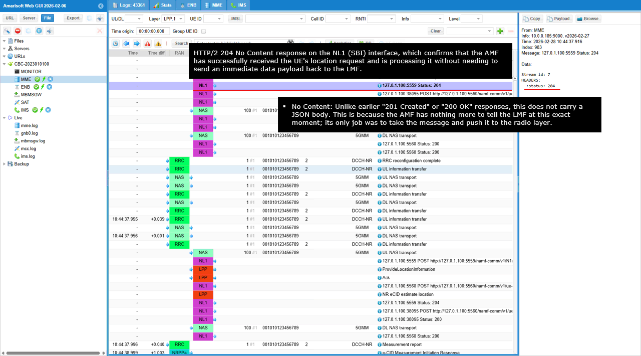
This is the AMF response to the UE specific N1/N2 message transfer that carried the LPP RequestLocationInformation.
The AMF returns HTTP status 204, which means the request was accepted but there is no response body to return. This is used when the AMF has nothing additional to report at the SBI layer beyond successful reception. The practical meaning is that the AMF has taken the LPP payload and will proceed with delivery toward the UE over the radio path, and any later outcomes will be reported via the configured notification callbacks rather than in this immediate HTTP response.
This shows the LMF sending the UE specific N1 message transfer to the AMF that carries the LPP request toward the test UE.
The HTTP POST target is /namf-comm/v1/ue-contexts/imsi-001010123456789/n1-n2-messages, so the message is bound to the UE context for that IMSI. The JSON container includes n1MessageContainer with n1MessageClass set to LPP and n1MessageContent pointing to contentId lpp-pdu. This tells the AMF the payload is an LPP N1 message to be delivered to the UE. The attached multipart part has Content-Type application/vnd.3gpp.5gnas with Content-Id lpp-pdu. This is the NAS encoded LPP payload that the AMF will forward over the radio path. The request carries nfid to identify the LMF instance, lcsCorrelationId to link it to the ongoing location procedure, n1n2FailureTxfNotifURI to define where failure notifications should be sent, and pei with the UE IMEI to bind delivery to the specific device.
This is the AMF response to the UE specific N1 transfer request that carried the LPP RequestLocationInformation.
The AMF returns HTTP status 200, meaning the request was accepted and the transfer procedure has started. The key field is cause with the value N1_N2_TRANSFER_INITIATED. In this context, it indicates the AMF has initiated delivery of the N1 payload toward the UE. It confirms initiation of delivery, but it does not yet confirm that the UE has received the message or that the UE has produced the location result.
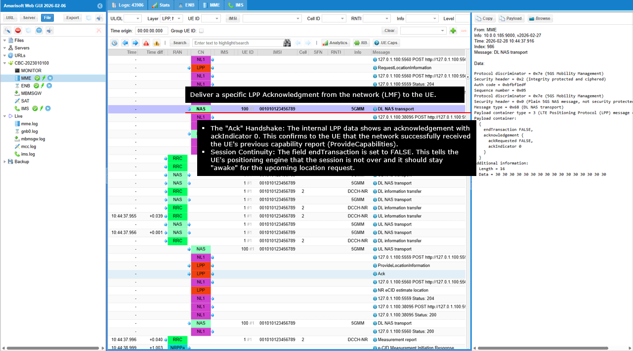
This shows a downlink DL NAS transport carrying an LPP Ack from the network to the UE.
The outer NAS container is DL NAS transport in 5GMM with a security header indicating integrity protection and ciphering, so the acknowledgement is delivered under the active NAS security context. payload container type is 3, which indicates the payload is an LPP message. The embedded LPP message is Ack. Inside the acknowledgement field, ackRequested is FALSE and ackIndicator is 0. This tells the UE that the network has acknowledged the earlier UE message without requesting another acknowledgement back. endTransaction is FALSE, which means the positioning session remains open and the UE should stay ready for the next LPP procedure step, such as RequestLocationInformation and the follow up measurement and location reporting.
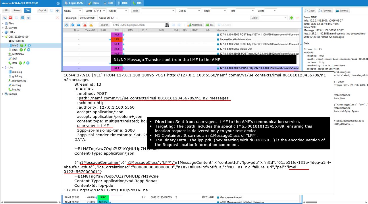
This shows the LMF initiating a UE specific N1/N2 message transfer toward the AMF to deliver an LPP payload.
The HTTP request is a POST to /namf-comm/v1/ue-contexts/imsi-001010123456789/n1-n2-messages. This path binds the transfer to the UE context identified by that IMSI. user-agent is LMF, so this is coming from the location server side. The body is multipart/related. The JSON control section includes n1MessageContainer with n1MessageClass set to LPP and it references n1MessageContent by contentId lpp-pdu. This means the transfer is N1 only and the AMF will forward the LPP message to the UE over NAS. The second part is the actual binary NAS payload. It is attached as Content-Type application/vnd.3gpp.5gnas with Content-Id lpp-pdu. This binary content is the encoded LPP message being delivered in this step. The request also includes nfid to identify the LMF instance, lcsCorrelationId to link this transfer to the ongoing location procedure, n1n2FailureTxfNotifURI to define where failures should be reported, and pei carrying the UE IMEI so the AMF can associate the transfer with the correct device identity.
This is the AMF response to the UE specific N1/N2 transfer request that carried the LPP message.
The AMF returns HTTP status 200, which means the request was accepted and the delivery procedure has been started. The key field is cause with the value N1_N2_TRANSFER_INITIATED. In this case it confirms the AMF has initiated delivery of the N1 payload toward the UE for this IMSI context. It is an internal handoff confirmation, not the UE receipt and not the final positioning result.
This shows the LPP RequestLocationInformation being delivered to the UE inside a DL NAS transport, so these are the positioning instructions that the UE positioning engine will execute.
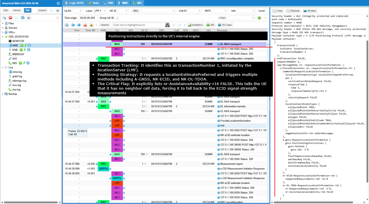
The key identifier is transactionID with transactionNumber 1. endTransaction is FALSE, so the UE is expected to respond later with ProvideLocationInformation for the same transaction. The requestLocationInformation payload sets locationInformationType to locationEstimatePreferred. This tells the UE to compute a position estimate result, not only to return raw measurement data. qos is included with responseTime set to 3, so the UE should attempt to produce the result within that time budget. verticalCoordinateRequest is FALSE and velocityRequest is FALSE, so altitude and velocity are not requested. locationCoordinateTypes indicates the allowed output formats. ellipsoidPoint and ellipsoidPointWithAltitude are TRUE, so the UE can return latitude and longitude and may include altitude if available. In the method specific parts, a-gnss-RequestLocationInformation is present with gnss-Method and basic positioningInstructions, while fineTimeAssistanceMeasReq, adrMeasReq, and multipleFreqMeasReq are all FALSE and assistanceAvailability is FALSE, meaning no extra GNSS assistance or special measurement requests are being used here. nr-ECID-RequestLocationInformation-r16 is present, so NR eCID is requested as part of the location estimate process. nr-DL-TDOA-RequestLocationInformation-r16 is also present. It includes nr-RequestedMeasurements-r16 and sets nr-AssistanceAvailability-r16 to FALSE, meaning the network is not providing NR DL-TDOA assistance data in this step, even though the UE has indicated support for NR DL-TDOA capability.
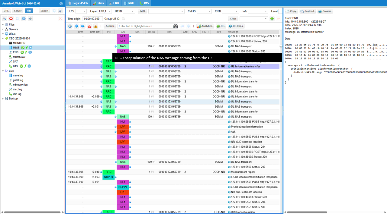
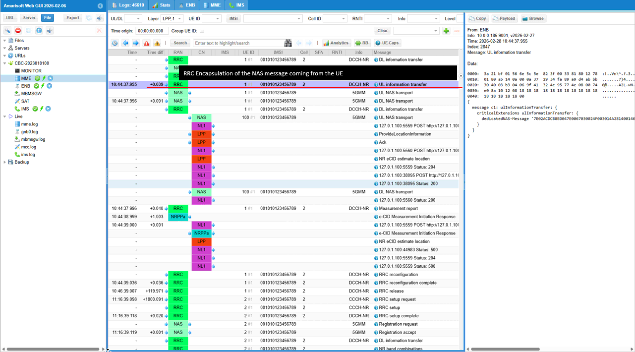
This shows an RRC UL information transfer message, which is how the UE sends a dedicated NAS payload back to the core network over the RRC signaling channel. This is just RRC Encapsulation of NAS message
This shows the UE sending LPP ProvideCapabilities inside an uplink UL NAS transport, which is the direct response to the earlier LPP RequestCapabilities.
The outer NAS message is UL NAS transport with payload container type 3, meaning the payload is an LPP message. The LPP transactionID uses transactionNumber 0, and endTransaction is TRUE, so the UE is closing the capability exchange transaction. acknowledgement shows ackRequested TRUE, which means the UE expects the network to send an LPP Ack back. In provideCapabilities-r9, commonIEsProvideCapabilities includes lpp-message-segmentation-r14, indicating the UE supports segmented LPP messages. a-gnss-ProvideCapabilities indicates GNSS support with gnss-SupportList showing gnss-Id gps, plus gnss-Signals and agnss-Modes. locationCoordinateTypes shows what coordinate outputs the UE can provide, with ellipsoidPoint TRUE and ellipsoidPointWithAltitude TRUE. nr-ECID-ProvideCapabilities-r16 is present and indicates NR eCID measurement support. It includes nr-ECID-MeasSupported-r16 and shows both periodicalReporting-r16 supported and triggeredReporting-r16 supported. nr-DL-TDOA-ProvideCapabilities-r16 is present and provides NR DL-TDOA related support and detailed DL-PRS capability. nr-DL-TDOA-PRS-Capability-r16 reports limits such as maxNrofDL-PRS-ResourceSetPerTRPPerFrequencyLayer-r16 equal to 1, maxNrofTRP-AcrossFreqs-r16 equal to 4, and maxNrofPosLayers-r16 equal to 1. dl-PRS-ResourcesBandCombinationList-r16 indicates support for band 78. nr-DL-TDOA-MeasurementCapability-r16 indicates RSTD measurement per TRP pair in FR1 and FR2 and shows PRS RSRP measurement support for FR1 and FR2. nr-DL-PRS-QCL-ProcessingCapability-r16 and nr-DL-PRS-ProcessingCapability-r16 report processing capability for band 78, including dl-PRS-BufferType-r16 type1, processing duration fields, maxNumOfDL-PRS-ProcessedPerSlot-r16 equal to 6, and maxSupportedFreqLayers-r16 equal to 1. periodicalReporting-r16 with posModes indicates periodic reporting capability for these NR positioning measurements.
This is a DL NAS transport that carries an LPP Ack from the network to the UE.
payload container type is 3, so the embedded payload is an LPP message. The LPP payload shown on the right is acknowledgement, not a new request. endTransaction is FALSE, which means the LPP session remains open and the network may send more positioning messages after this. In the acknowledgement field, ackRequested is FALSE. This means the network is not asking the UE to acknowledge this Ack. ackIndicator is 0. This value links the Ack to the previous UE LPP message that requested acknowledgement, so the UE can match this receipt to the correct prior transaction.
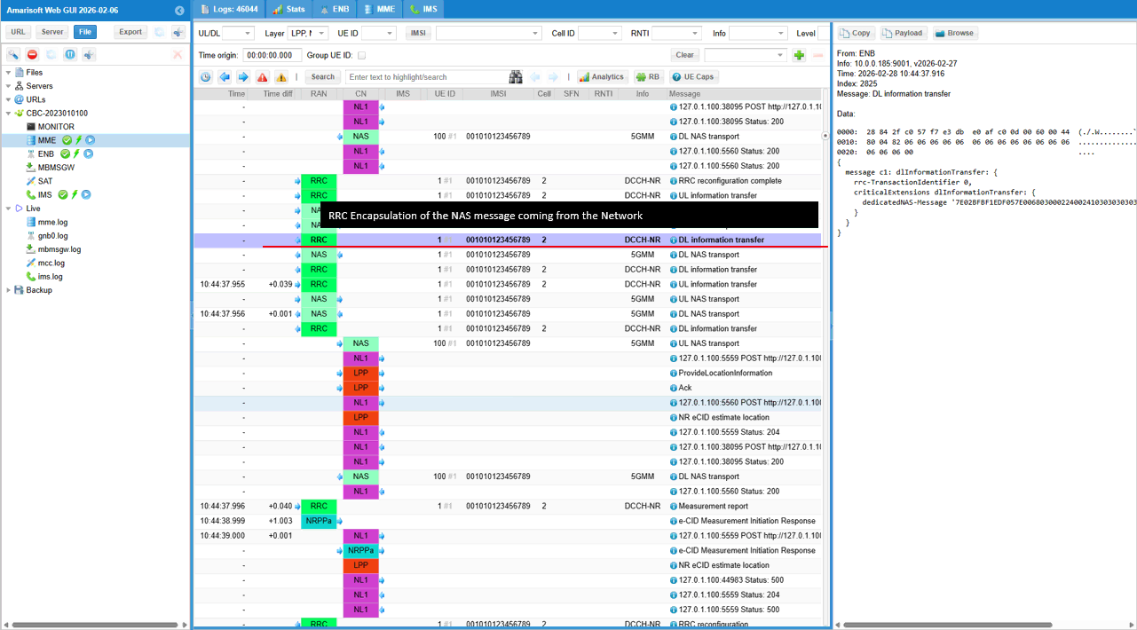
This shows the downlink RRC carrier that transports a NAS message from the network to the UE. This is just RRC Encapsulation of a NAS message (DL NAS Transport in this case)
This is the DL NAS transport that carries the LPP RequestLocationInformation to the UE. It is the point where the locationServer gives the UE the concrete positioning task.
transactionID shows transactionNumber 1 and endTransaction is FALSE, so this is an active location transaction that will be completed by the UE response. lpp-MessageBody is requestLocationInformation. locationInformationType is locationEstimatePreferred, so the UE is asked to compute and return a position estimate. qos includes responseTime 3, verticalCoordinateRequest FALSE, and velocityRequest FALSE. This means the UE should respond within about 3 seconds, and the network is not requesting altitude or velocity as mandatory inputs. locationCoordinateTypes shows ellipsoidPoint TRUE and ellipsoidPointWithAltitude TRUE. This means the network can accept either a 2D latitude/longitude point or a latitude/longitude point with altitude if available. a-gnss-RequestLocationInformation is present with gnss-Method and basic positioningInstructions. fineTimeAssistanceMeasReq FALSE, adrMeasReq FALSE, multipleFreqMeasReq FALSE, and assistanceAvailability FALSE indicate no extra GNSS assistance or special measurements are requested here. nr-ECID-RequestLocationInformation-r16 is included, so NR eCID based information is requested for the estimate. nr-DL-TDOA-RequestLocationInformation-r16 is included with nr-RequestedMeasurements-r16 and nr-AssistanceAvailability-r16 FALSE, meaning the network requests NR DL-TDOA related measurements but is not providing DL-TDOA assistance data in this step.
This shows the downlink RRC carrier that transports a NAS message from the network to the UE. This is just RRC Encapsulation of a NAS message (DL NAS Transport in this case)
This shows the UE sending an RRC UL information transfer. It is the radio layer wrapper used when the UE sends a dedicated NAS message back toward the core network.
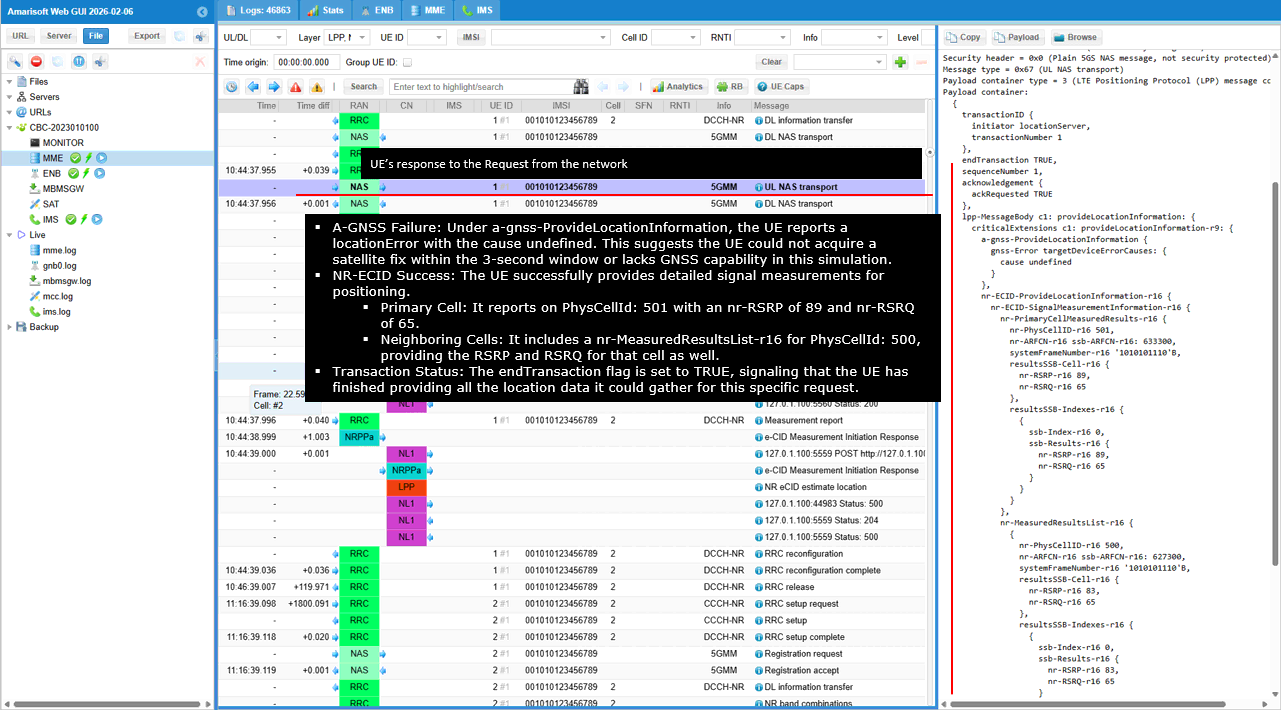
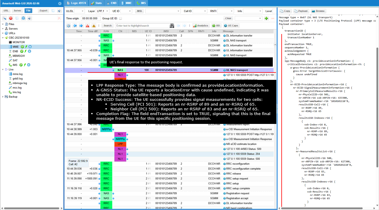
This shows the UE's LPP ProvideLocationInformation response for transactionNumber 1. endTransaction is TRUE, which means the UE is closing this location request transaction and returning everything it could gather for this request.
Under a-gnss-ProvideLocationInformation, the UE reports a locationError with cause set to undefined. This means the GNSS part of the request did not produce a valid location estimate in this attempt, so the A-GNSS method did not succeed here. At the same time, the NR eCID part does return usable radio measurements. Under nr-ECID-ProvideLocationInformation-r16, the UE reports nr-PrimaryCellMeasuredResults-r16 for nr-PhysCellId 501 on NR ARFCN 633300. The reported serving cell values are nr-RSRP 89 and nr-RSRQ 65. It also includes SSB based results in resultSSB-Cell-r16, again showing SSB index 0 with nr-RSRP 89 and nr-RSRQ 65. The UE also reports neighbor cell measurements in nr-MeasuredResultsList-r16. For nr-PhysCellId 500 on NR ARFCN 627300, it provides measured results with nr-RSRP 83 and nr-RSRQ 65. The SSB specific result for that neighbor cell is also included in resultSSB-Indexes-r16 with SSB index 0, nr-RSRP 83, and nr-RSRQ 65. So the important point is that the GNSS based estimate failed, but the UE still successfully returned NR eCID measurement data for the serving cell and neighbor cell, which can be used by the network for positioning.
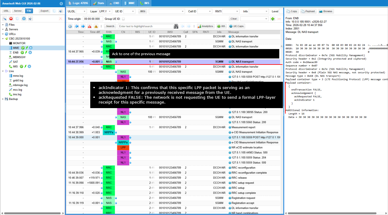
This shows a DL NAS transport carrying an LPP Ack from the network to the UE.
The embedded LPP message is an acknowledgement. ackIndicator is 1, which means this Ack is tied to the previous UE LPP message in transaction 1, namely the UE response that carried ProvideLocationInformation. ackRequested is FALSE, so the network is not asking the UE to send another LPP acknowledgement back for this packet. endTransaction is FALSE. This means the Ack itself does not close the broader LPP session context, even though it confirms receipt of the previous UE message.
This shows DL information transfer on the RRC layer. It is the radio layer wrapper used by the gNB to deliver a dedicated NAS message from the core network to the UE.
This shows the UE sending the final LPP ProvideLocationInformation for transactionNumber 1. The key point is endTransaction TRUE, which means the UE has finished this specific location request and is returning the last location related information it could collect.
The A-GNSS part reports a failure. Under a-gnss-ProvideLocationInformation, the UE sends locationError with cause set to undefined. This means the satellite based method did not produce a usable location estimate in this attempt. The NR eCID part succeeds and provides usable radio measurements. In nr-ECID-ProvideLocationInformation-r16, the serving cell is reported in nr-PrimaryCellMeasuredResults-r16 with nr-PhysCellId 501 and nr-ARFCN-r16 633300. The reported serving cell values are nr-RSRP 89 and nr-RSRQ 65. The SSB specific result is also included with sSB-Index 0, nr-RSRP 89, and nr-RSRQ 65. The UE also reports neighbor cell measurement results in nr-MeasuredResultsList-r16. For nr-PhysCellId 500 on nr-ARFCN-r16 627300, it reports nr-RSRP 83 and nr-RSRQ 65. The SSB result for that neighbor cell is also included with sSB-Index 0, nr-RSRP 83, and nr-RSRQ 65. Overall, this message means the UE could not provide the requested A-GNSS location estimate, but it successfully returned NR eCID measurement data for both the serving cell and the neighbor cell, which the network can still use for positioning.
This shows the AMF forwarding the UE's LPP response to the LMF through the UE specific N1 notification callback.
The HTTP POST goes to /namf-comm/v1/N1/imsi-001010123456789/notify/imei=012345670000001. This means the notification is tied to the specific UE identified by IMSI 001010123456789 and IMEI 012345670000001. n1NotifySubscriptionId is 0000000000000002. This matches the UE specific N1 subscription that was created earlier, so the LMF knows this message belongs to that LPP session. n1MessageContainer shows n1MessageClass set to LPP. This confirms that the attached payload is the UE's LPP message, not a generic NAS notification. The notification also includes lcsCorrelationId, which links this message to the same positioning session, and location context fields such as GUAMI and NCGI. In NCGI, the NR Cell ID is 001234502, so the LMF can identify the serving cell context from which the UE sent the response. The attached part with Content-Type application/vnd.3gpp.5gnas and Content-Id notifyN1 is the actual NAS container carrying the UE's LPP ProvideLocationInformation message. This is how the UE's final positioning response is delivered from the AMF back to the LMF.
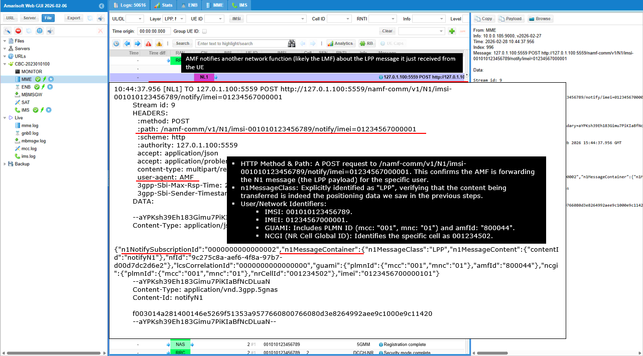
This shows the LPP ProvideLocationInformation message after it has reached the location server side and been fully decoded.
The key transaction fields are transactionNumber 1 and endTransaction TRUE. This means the UE is closing this location request transaction and returning the final result it could produce. ackRequested is TRUE, so the UE is also asking the location server to acknowledge receipt of this message at the LPP layer. For the A-GNSS part, the UE does not provide a valid GNSS position. Under a-gnss-ProvideLocationInformation, it reports locationError with cause undefined. In other words, the GNSS based method did not succeed in this attempt. For the NR eCID part, the UE does provide useful radio measurement data. In nr-ECID-ProvideLocationInformation-r16, the primary cell result is for PCI 501 on ARFCN 633300, with nr-RSRP 89 and nr-RSRQ 65. The SSB specific result for that same serving cell is also included with SSB index 0, again showing nr-RSRP 89 and nr-RSRQ 65. The UE also reports neighbor cell data in nr-MeasuredResultsList-r16. The neighbor cell is PCI 500 on ARFCN 627300, with nr-RSRP 83 and nr-RSRQ 65. Its SSB specific result is also included with SSB index 0, showing nr-RSRP 83 and nr-RSRQ 65. So the overall meaning is clear. The GNSS estimate failed, but the UE successfully returned NR eCID measurement results for both the serving cell and the neighbor cell. Those measurements are the data the network can now use for the eCID based location estimate.
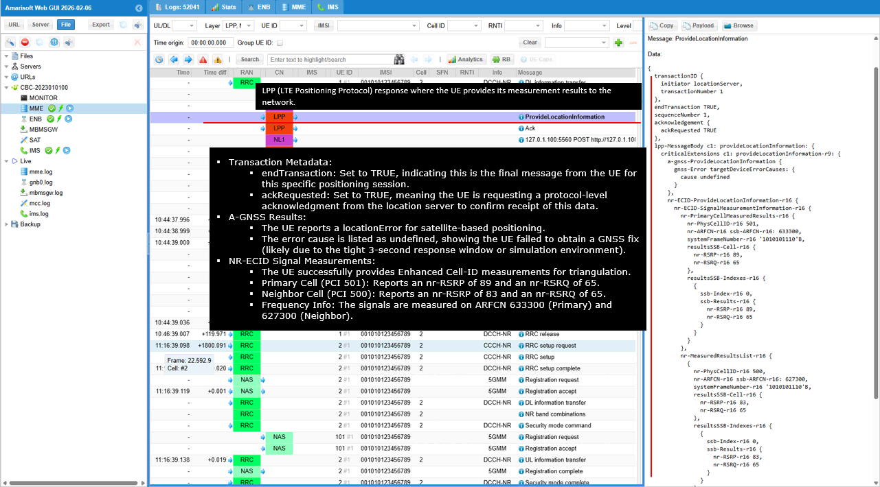
This shows the LPP Ack generated by the location server after it received the UE's ProvideLocationInformation.
The key field is ackIndicator set to 1. This tells you that this message is acknowledging the previous UE LPP message in transaction 1, which is the ProvideLocationInformation carrying the final positioning data. ackRequested is FALSE. This means the network is not asking the UE to send another acknowledgement back for this Ack. endTransaction is FALSE. So even though this message acknowledges receipt of the UE report, the LPP layer itself is not explicitly closing the overall session with this packet.
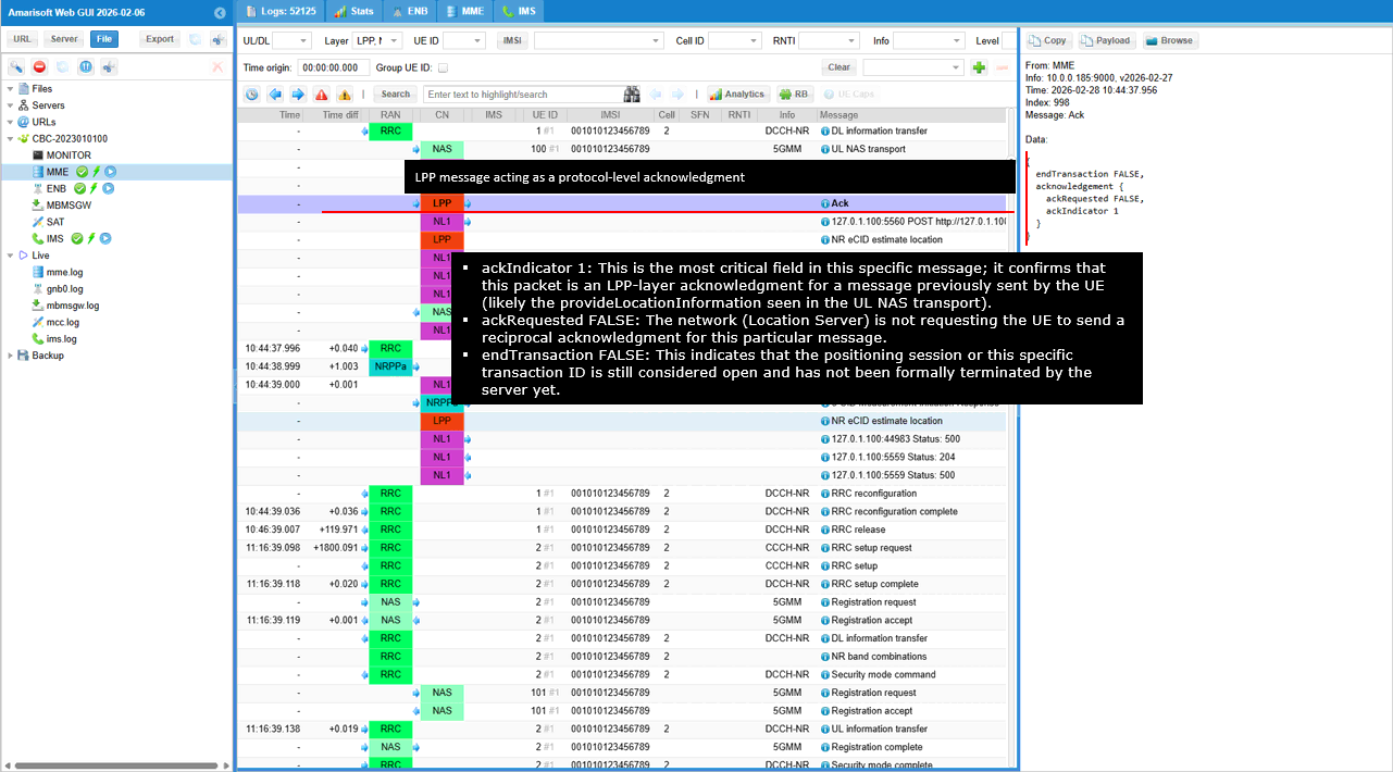
This shows the LMF sending another UE specific N1 message through the AMF so the message can be delivered down to the UE.
The HTTP POST goes to /namf-comm/v1/ue-contexts/imsi-001010123456789/n1-n2-messages. This means the transfer is tied to the UE context identified by IMSI 001010123456789. The sender is the LMF, as shown by user-agent LMF. The JSON control part contains n1MessageContainer with n1MessageClass set to LPP. This tells the AMF that the payload is an LPP message for the UE. The message is N1 only, so it is a UE directed NAS delivery rather than an NRPPa transfer to the gNB. The request also includes nfid, lcsCorrelationId, and pei. nfid identifies the LMF instance. lcsCorrelationId ties this message to the same ongoing positioning session. pei carries the UE IMEI, so the AMF can bind the delivery to the correct device. The multipart attachment has Content-Type application/vnd.3gpp.5gnas and Content-Id lpp-pdu. That binary payload is the actual NAS encoded LPP message. In this step, it is the LPP Ack that the network is sending back to the UE after receiving the UE's ProvideLocationInformation.
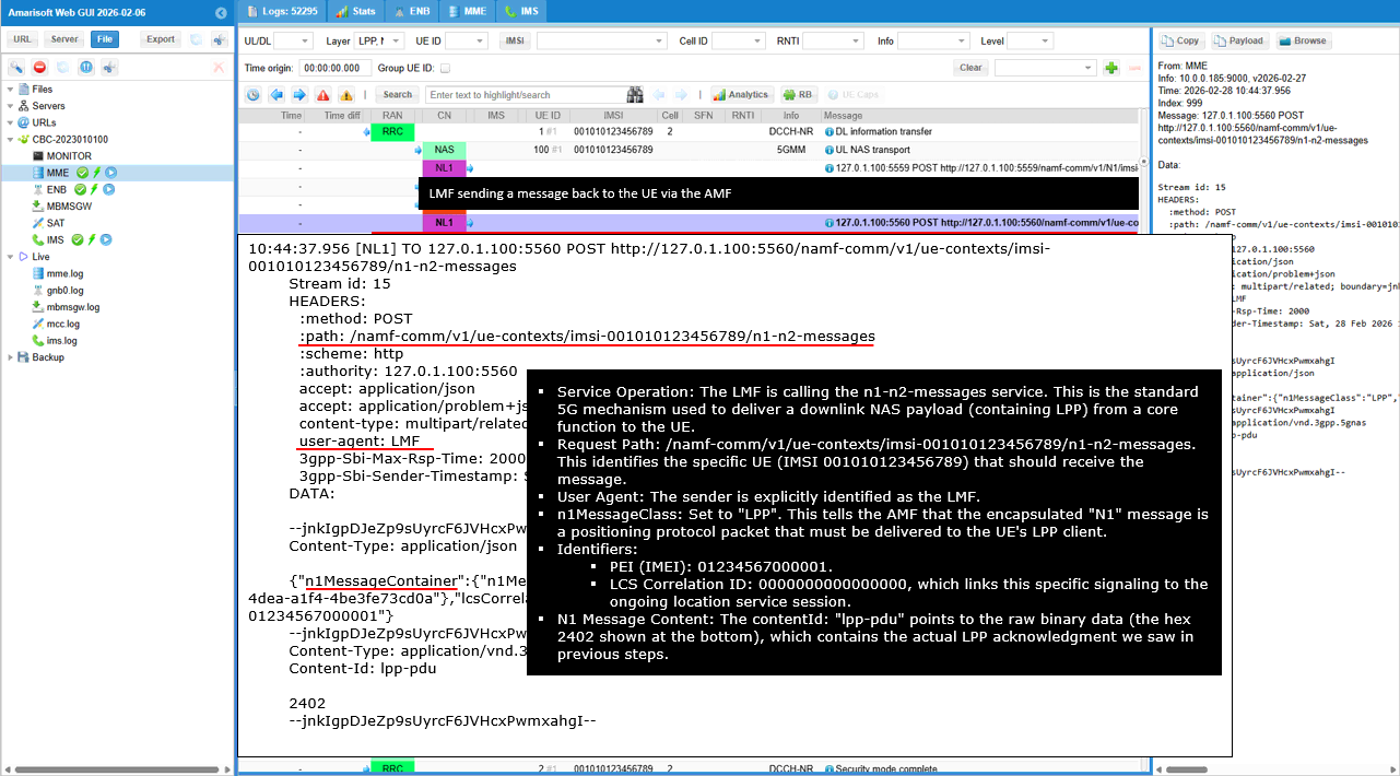
This indicates that the LPP side and the NRPPa side did not both complete successfully enough to produce a final NR eCID location estimate.
The first line, NR eCID: NRPPa meas results not received, means the location server did not receive the required network side NRPPa measurement results from the gNB. In other words, the UE to server path over LPP worked and the UE did send its measurement information, but the gNB to server path over NRPPa did not return the measurement response that the location server expected. The second line, NR ECID UE position estimation error, is the consequence of that missing NRPPa data. Even though the UE reported serving cell and neighbor cell measurements through LPP, the server could not complete the final position calculation because the full NR eCID procedure needs the corresponding network side measurement information as well. So the overall meaning is that the UE side reporting succeeded, but the network side NRPPa measurement reporting failed or was not delivered, and therefore the final NR eCID position estimate could not be generated.
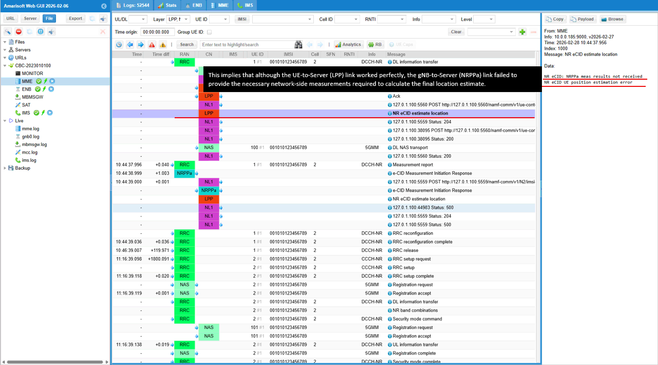
This shows a normal successful SBI acknowledgement between network functions.
The HTTP status is 204 No Content. In 5G SBA, this means the receiving network function accepted and processed the request successfully, but it does not need to return any payload body. In this context, it indicates that the AMF to LMF notification or the related callback handling completed successfully at the HTTP interface level. The signaling message was received, understood, and consumed correctly, so there is nothing more to send back in the response. So this line is not an error and not a missing decode. It is simply the expected confirmation that the inter-network-function signaling exchange finished successfully.
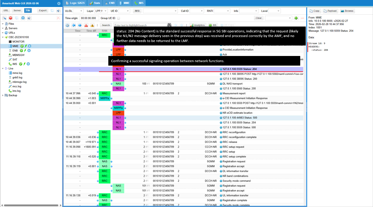
This shows the LMF sending a UE specific N1 message transfer to the AMF after it received the UE's ProvideLocationInformation.
The HTTP POST goes to /namf-comm/v1/ue-contexts/imsi-001010123456789/n1-n2-messages, so the message is targeted to that specific UE context. The sender is the LMF, as shown by user-agent LMF. The key field is n1MessageClass set to LPP. This means the payload being pushed to the UE is an LPP message. In this case, the attached binary payload 2402 is the encoded LPP Ack that the LMF is sending back to acknowledge the UE's previous ProvideLocationInformation message. The request also includes lcsCorrelationId, which ties this delivery to the same positioning session, and pei, which identifies the UE device by IMEI. The multipart attachment with Content-Type application/vnd.3gpp.5gnas and Content-Id lpp-pdu is the actual NAS container that the AMF will forward to the UE.
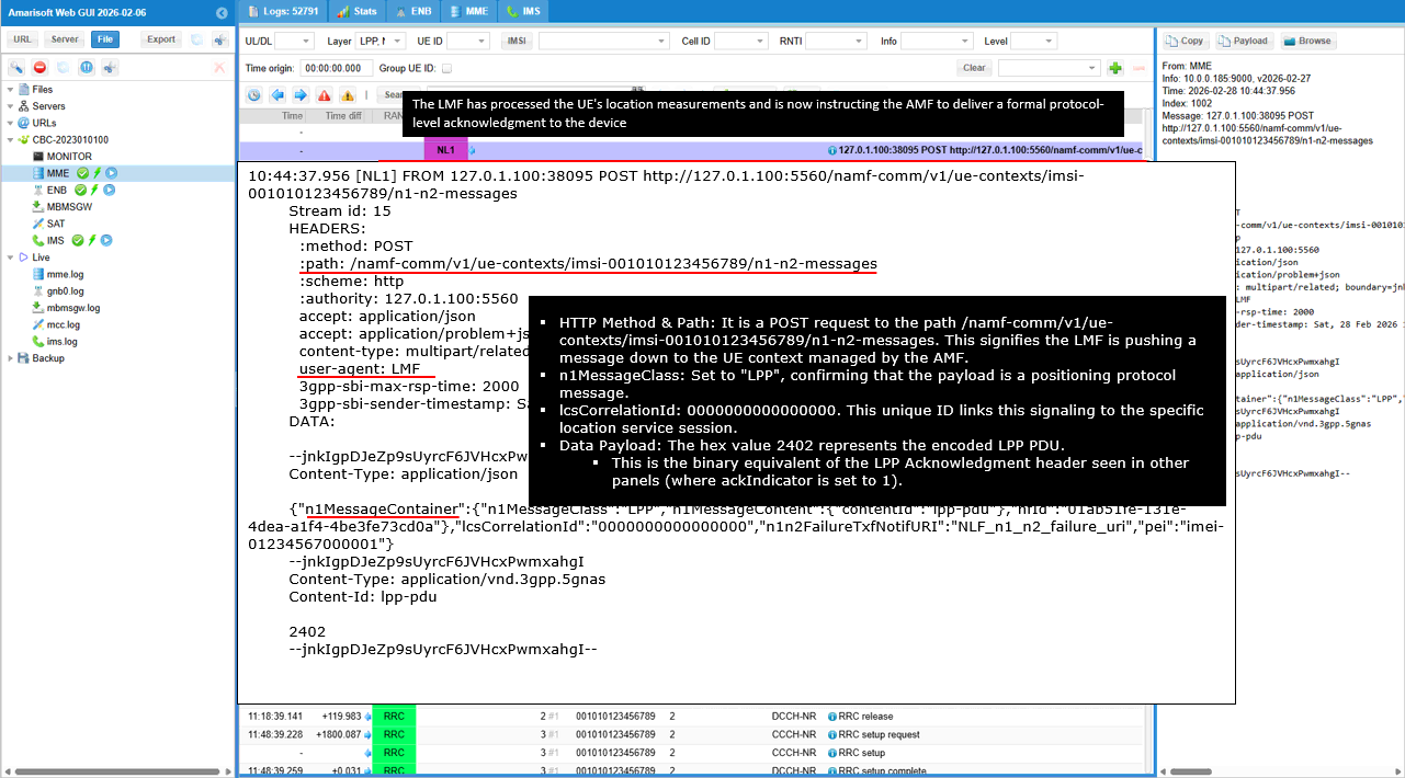
This shows the AMF response to the LMF after the LMF asked it to deliver the LPP Ack to the UE. The HTTP status is 200, which means the AMF accepted the request successfully at the SBI level. The key field is cause set to N1_N2_TRANSFER_INITIATED. This means the AMF has started the UE delivery procedure for that N1 message. In this specific step, that N1 message is the LPP Ack sent by the LMF to acknowledge the UE's earlier ProvideLocationInformation. So this does not mean the UE has already consumed the Ack. It means the AMF has successfully received the LMF instruction and has initiated forwarding of the NAS message toward the UE over the radio path.
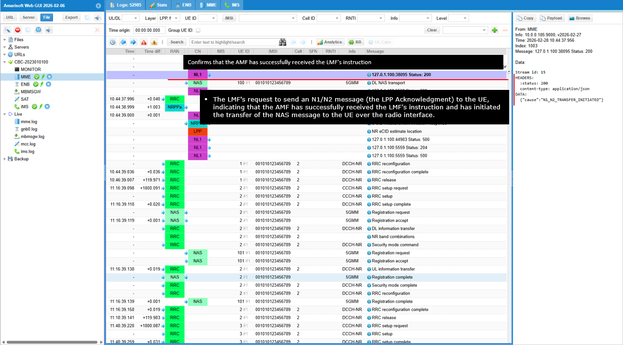
This DL NAS transport is the network's formal LPP acknowledgement to the UE after receiving the UE's ProvideLocationInformation message.
The key field is ackIndicator set to 1. This shows that the message is acknowledging the UE's previous LPP response for transaction 1, which was the final location information report. ackRequested is FALSE, so the network is not asking the UE to send another acknowledgement back for this packet. endTransaction is FALSE, which means this packet itself does not explicitly close the overall LPP session context. It only confirms that the location server successfully received the UE's measurement report.
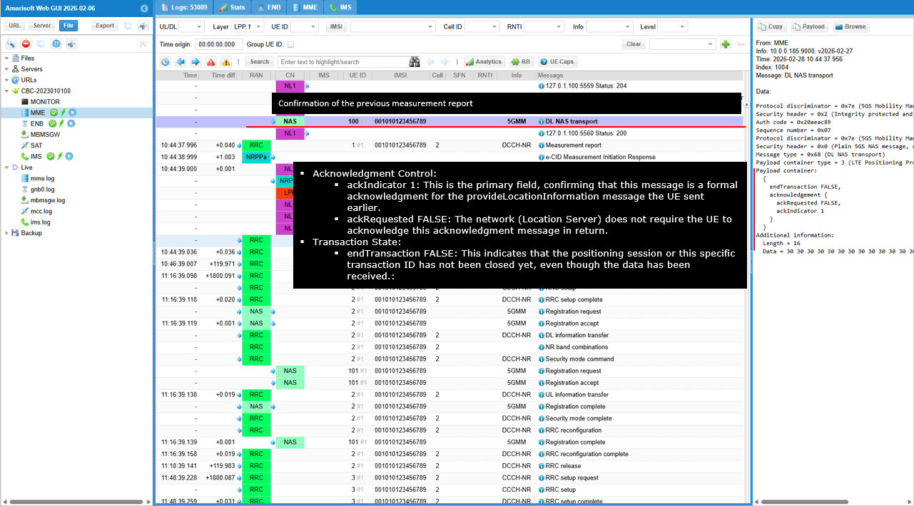
This shows the AMF acknowledging the LMF request and confirming that delivery toward the UE has been initiated.
The HTTP status is 200, which means the AMF accepted the request successfully at the SBI level. The key field is cause set to N1_N2_TRANSFER_INITIATED. This means the AMF has started the UE delivery procedure for the N1 message. In this specific step, the N1 message is the LPP acknowledgement that the location server is sending back to the UE after receiving the UE's ProvideLocationInformation. So this line does not mean the UE already received the message. It means the AMF has taken the message from the LMF and has started forwarding it toward the UE over the radio path.
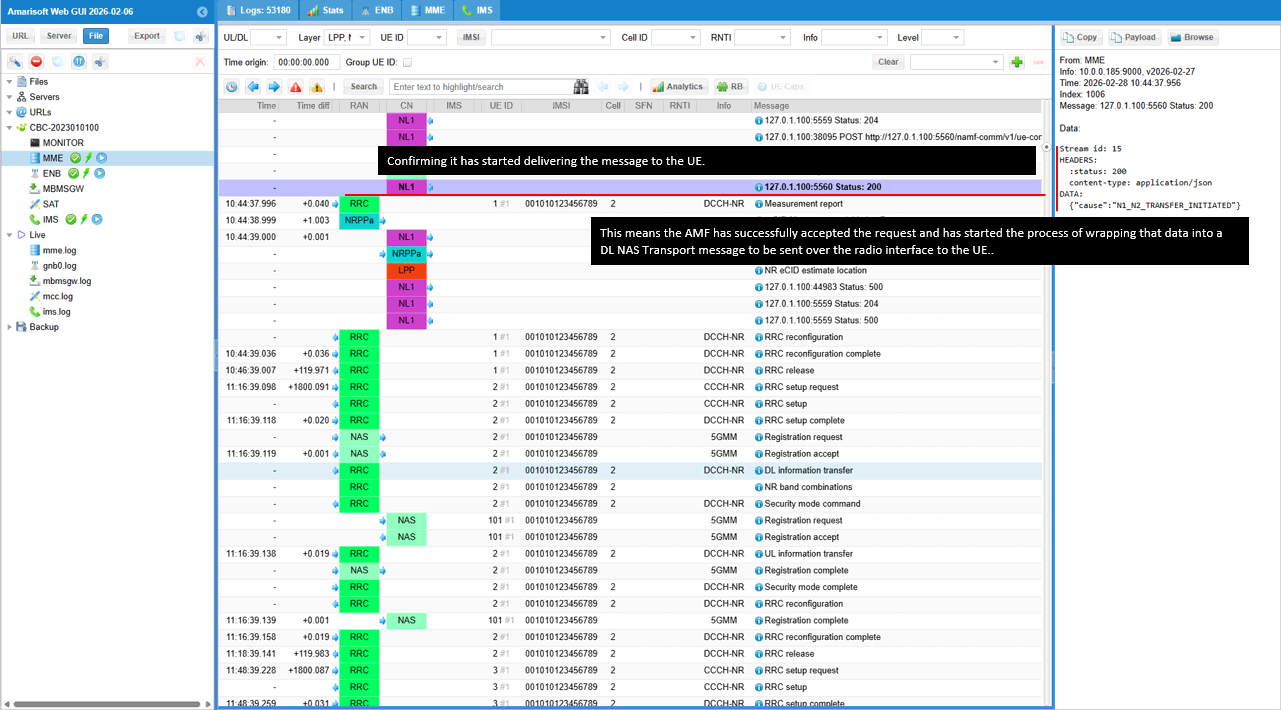
This is the RRC Measurement Report sent from the UE to the gNB as part of the network configured measurement procedure. The key field is measId 2, which tells you which measurement configuration triggered this report.
In the serving cell result, the UE reports physCellId 501 with rsrp 89 and rsrq 65. This confirms that the UE is currently camped on PCI 501 and that this cell is the stronger one in terms of received power. In the neighbor cell result, the UE reports physCellId 500 with rsrp 83 and rsrq 65. This means the neighbor cell is also detected and measured, but its received power is lower than the serving cell by about 6 dB, while the signal quality is the same. For this LPP eCID test, this message is important because it proves that the UE measurement framework is working correctly at the RRC level and that the UE can report both serving cell and neighbor cell radio measurements, which are the basic inputs needed for eCID related positioning.
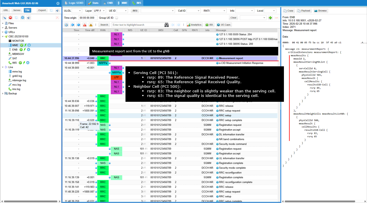
This shows the NRPPa e-CID Measurement Initiation Response coming back from the gNB to the LMF. This is the network side measurement response that complements the UE side LPP measurements.
The message is identified as successfulOutcome for procedureCode e-CIDMeasurementInitiation with nrppaTransactionID 2. That confirms this response belongs to the same NRPPa measurement request that the LMF started earlier. The key identifiers are lMF-UE-Measurement-ID and RAN-UE-Measurement-ID, both set to 1. These values tie the returned measurement result to the specific UE measurement instance. The e-CID-MeasurementResult includes the serving cell identity. You can see the PLMN identity and the nG-RAN cell identifier, along with the serving cell TAC. This tells the LMF exactly which cell the gNB used as the reference cell for the result. An important part is servingCellTAC and the nGRANAccessPointPosition. The access point position gives the geographic reference of the serving cell, including latitude, longitude, altitude, and uncertainty related fields. This location anchor is essential because eCID positioning combines radio measurements with the known location of the serving base station. The measurement result also includes radio measurements for the serving cell. In the visible part, the gNB reports nr-RSRP for PCI 501 on NR ARFCN 633300, and the value is 89. This matches the serving cell measurement trend already seen from the UE side. The panel also starts to show nr-RSRQ information just below, indicating that quality measurements are also part of the returned network side result. For the serving cell, the gNB reports nr-RSRQ for PCI 501 on ARFCN 633300 with a value of 65. This complements the earlier nr-RSRP value of 89, so now the LMF has both signal strength and signal quality for the serving cell from the network side. The response also includes NR-TADV with a value of 24. This is very important for eCID because it provides the timing advance related distance information between the UE and the serving gNB. The message then includes neighbor cell measurements as well. For PCI 500 on ARFCN 626592, the gNB reports nr-RSRP 83 and nr-RSRQ 65. This means the network side result is not limited to the serving cell. It also includes neighbor cell radio measurements that can be used together with the serving cell result for location estimation. Overall, this message is very important because it proves that the gNB did return the NRPPa eCID measurement result to the LMF. In other words, this is the network side counterpart of the UE measurements, carrying serving cell identity, base station position, and radio measurement values needed by the LMF for final eCID location processing.
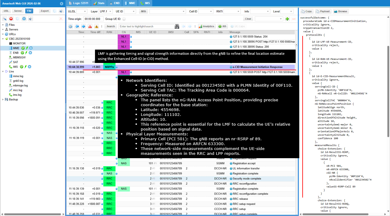
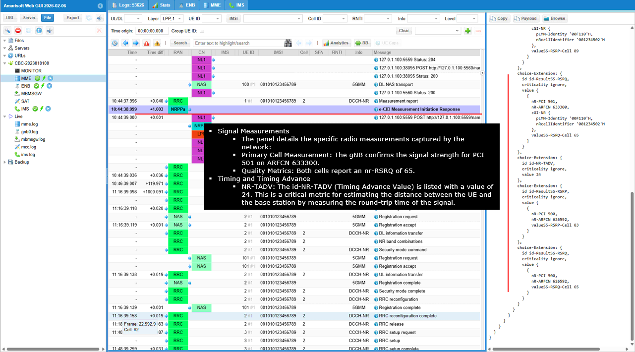
This shows the AMF forwarding the gNB�s NRPPa response to the LMF through the UE specific N2 notification callback.
The HTTP POST goes to /namf-comm/v1/N2/imsi-001010123456789/notify/imei=012345670000001. This means the notification is tied to the specific UE context identified by IMSI 001010123456789 and IMEI 012345670000001. The important field is n2NotifySubscriptionId. This links the message to the previously created UE specific N2 subscription, so the LMF knows this NRPPa notification belongs to the same positioning session. The JSON body contains n2InfoContainer with n2InformationClass set to NRPPa. This confirms that the payload is network side positioning information coming from the gNB, not UE side LPP information. Inside nrppaInfo, the NRPPa PDU is referenced through the attached binary part with Content-Id notifyN2 and Content-Type application/vnd.3gpp.ngap. That attached payload is the actual encoded NRPPa measurement response from the gNB. So this step is the SBI forwarding stage where the AMF delivers the gNB�s eCID measurement result up to the LMF for final location processing.
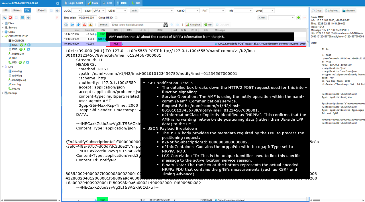
Test 2 : ECID with Commercial UE
The purpose and overall process of this test is almost same as the previous test. The main difference is DUT which is commercial UE as opposed to Amarisoft UEsim.
Configuration - UE
One of the difficulties in testing LPP with a commercial UE is figuring out how to trigger or enable the LPP functionality on the UE side. Unlike a test UE or UE simulator, a commercial UE usually does not provide a simple configuration parameter that directly says �enable LPP.� In many cases, LPP is activated only when the UE modem, Android or iOS framework, location service, SIM profile, and network signaling condition all match what the UE expects. Because of this, there is no single standard procedure that works for every phone, and each commercial UE may have its own way of enabling or exposing LPP behavior.
USIM/eSIM
For LPP testing with a commercial UE, the first requirement is that the phone must register normally to the Amarisoft network. Depending on the phone model, this can be done either by inserting the Amarisoft physical test SIM or by installing the Amarisoft eSIM profile.
Some iPhone regional models still have a nano-SIM slot, such as many EU versions, so the physical SIM can be used. Some US iPhone models do not have a physical SIM slot and support only eSIM, so the Amarisoft eSIM profile should be scanned and installed instead.
At this step, we are not verifying LPP yet. We are only confirming that the UE can use the correct SIM/eSIM, camp on the Amarisoft cell, and enter normal service. Once this basic registration works, we can move on to checking whether LPP signaling is triggered in the logs.
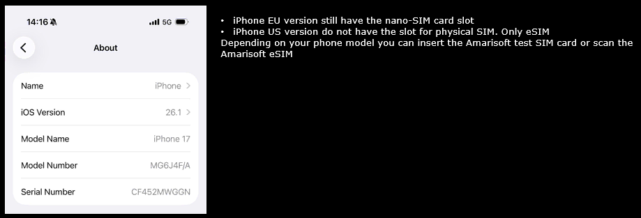
Network settings
After installing the Amarisoft SIM or eSIM, open the iPhone network settings and make sure the line is enabled. Go to Settings, select Mobile Service, then select the Amarisoft SIM or eSIM profile. In this example, PLMN 00101, telephone number matching with the default database profile impu: ["001010123456789", "tel:0600000000", "tel:600"]
Make sure Mobile Data is enabled, because LPP testing usually requires the UE to be fully registered and usable on the mobile network. Data Roaming should also be enabled when using a private test network, since the UE may treat the Amarisoft PLMN as a roaming network depending on the SIM profile and phone behavior.
In Network Selection, Automatic can be left enabled if the phone can find and select the Amarisoft network by itself. If the UE does not camp on the intended cell, disable Automatic and manually select the Amarisoft network from the list.
At this stage, the purpose is still basic UE readiness. We are checking that the phone uses the correct SIM/eSIM line, mobile data is enabled, roaming is allowed, and the UE can select the Amarisoft network before we start analyzing LPP signaling.
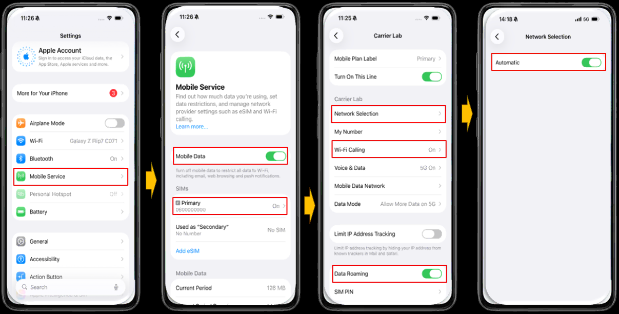
Voice and data settings
In the Voice & Data menu, make sure 5G is enabled. You can select either 5G Auto or 5G On, but for testing it is usually better to select 5G On so the UE tries to stay on 5G as much as possible.
Also make sure 5G Standalone is enabled. This is important when the test is based on NR SA, because without this option the iPhone may not use 5G SA even if the cell is available.
If the 5G Standalone toggle is blocked or cannot be enabled, it usually means the SIM/eSIM profile or carrier setting does not allow 5G SA. In that case, the UE may still connect to LTE or NSA, but NR SA based LPP testing will not work.
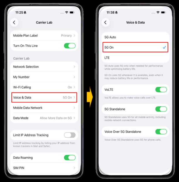
APN settings
In the Mobile Data Network menu, enter the APN used for user data. In this example, the Amarisoft default configuration is used, so the APN is set to default.
This APN should match the APN configured on the Amarisoft core network side. If the APN does not match, the UE may still register to the network, but user data may not work properly.
For IMS, no manual APN entry is needed in this menu in this setup. The UE requests IMS automatically when IMS service is enabled and supported by the network configuration.
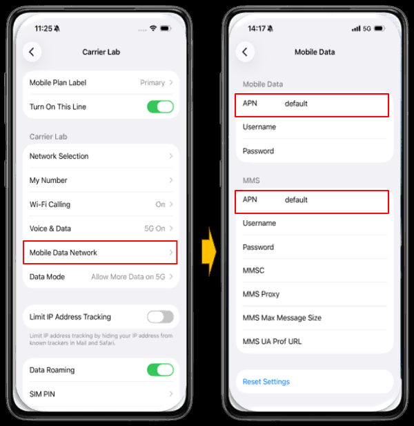
Configuration - Callbox
I have used gnb-positioning.cfg on Callbox (gNB) as it is without any modification.

I am using the mme-ims-nr-lpp-auto.cfg and ims-lpp.cfg which is copied and modified from mme-ims.cfg

In gnb-positioning.cfg , followings are configured

This configures the RF driver block so the call box knows which SDR devices to open and how many to allocate for the test. The driver name is set to sdr, so the software uses the SDR backend and expects device nodes like /dev/sdr0, /dev/sdr1, and so on.
If the downlink antenna count is 4 or more, it allocates four SDR devices and maps them to dev0 through dev3. Otherwise it checks the number of NR cells. If you run a single cell configuration, it uses only dev0. If you run a multi cell configuration, it allocates dev0 and dev1 so each cell can be served by its own SDR path. This is why N_CELLS impacts how many SDR cards are assigned.
This part defines the RF port mapping for the test so the software can build the correct set of transmit and receive paths for each NR cell.
The first RF port entry is always present. The second RF port entry is included only when N_CELLS is greater than 1. This is the mechanism that makes the same configuration file work for both one cell and two cell setups. If you run only one cell, the second port block is used, so there is no unused port and no extra SDR resource allocation. If you run two cells, the second port block becomes active.
This configuration defines the first NR cell used in the LPP eCID session. The key parameters are n_id_cell, dl_nr_arfcn, subcarrier_spacing, and ssb_pos_bitmap. n_id_cell determines the PCI and therefore which cell the UE camps on and measures. dl_nr_arfcn and band set the RF frequency for the test. subcarrier_spacing sets the numerology that impacts timing and measurement behavior. ssb_pos_bitmap controls which SSB locations are transmitted, so it affects initial access and measurement stability.
For two cell eCID, ncell_list is the important parameter. It enables the neighbor cell definition only when N_CELLS > 1. Without ncell_list, the setup becomes a single cell configuration and eCID neighbor based measurement is not possible.
For LPP validation, access_point_position is the important block. latitude, longitude, and altitude provide the reference cell site position used for positioning messages and result checking.
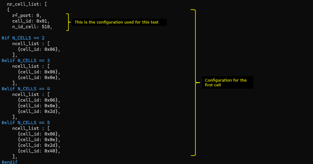
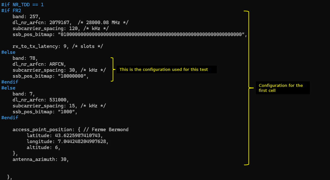
This configuration defines the second NR cell used in the LPP eCID session. The key parameters are n_id_cell, dl_nr_arfcn, subcarrier_spacing, and ssb_pos_bitmap. n_id_cell determines the PCI and therefore which cell the UE camps on and measures. dl_nr_arfcn and band set the RF frequency for the test. subcarrier_spacing sets the numerology that impacts timing and measurement behavior. ssb_pos_bitmap controls which SSB locations are transmitted, so it affects initial access and measurement stability.
For two cell eCID, ncell_list is the important parameter. It enables the neighbor cell definition only when N_CELLS > 1. Without ncell_list, the setup becomes a single cell configuration and eCID neighbor based measurement is not possible.
For LPP validation, access_point_position is the important block. latitude, longitude, and altitude provide the reference cell site position used for positioning messages and result checking.

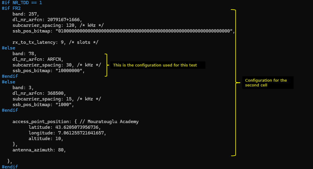
This block defines default NR cell behavior and the measurement settings needed before running the LPP procedure.
The important point in this configuration is the IMS related configuration and the PLMN configuration. In theory these parameters may not appear directly related to the positioning procedure, but when testing with real commercial UE devices we observed that these settings can strongly influence whether the UE enables LPP capability.
One key reason is related to emergency call behavior. Some commercial UE implementations enable LPP positioning capability only when the UE believes it is in an emergency call scenario. This behavior is related to regulatory requirements where the network must be able to determine the caller�s location during an emergency call. Because of this, certain UE activate the LPP positioning stack only when the network indicates support for IMS emergency services.
The parameters ims_emergency_support and ecall_over_ims_support indicate that the network supports IMS based emergency calls and eCall over IMS. When these parameters are enabled, the UE interprets the network as supporting emergency call procedures that require location reporting.
Another important configuration is the PLMN setting. The PLMN configuration determines how the UE classifies the network. Some UE apply different internal policies depending on the PLMN value they detect. If the PLMN corresponds to a commercial operator profile recognized by the UE, the device tends to enable normal service features including positioning procedures. If the PLMN is a test or unknown value, the UE may restrict certain behaviors or disable some advanced capabilities.
For this reason it is important to configure a PLMN value that allows the UE to behave as expected during the positioning test. Even though IMS emergency settings and PLMN configuration appear unrelated to positioning at first glance, they can indirectly determine whether the UE enables the LPP positioning capability in the test environment.
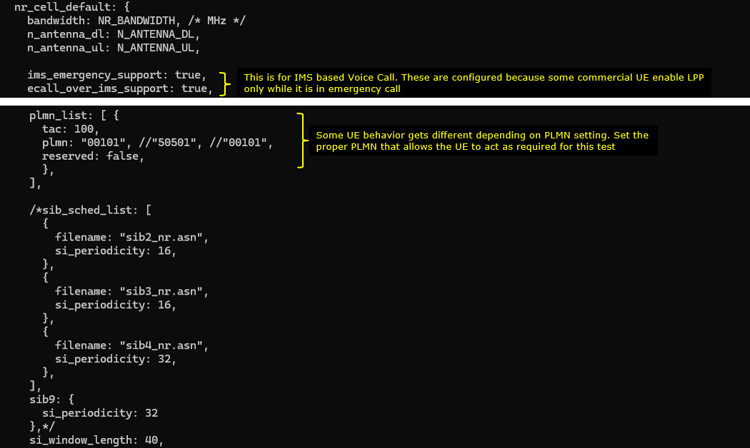
The important part is meas_config_desc. This is where the RRC measurement framework is enabled, with A1 and A2 thresholds and time_to_trigger values that control when measurements are considered stable. For a single cell setup only, nr_periodical enables periodic measurement reports(this is experimental purpose). The key parameters there are report_quantity_rsrp, report_quantity_rsrq, report_quantity_sinr, report_interval, report_amount, and max_report_cells. These ensure the UE keeps producing measurement results that the LPP eCID procedure can use.
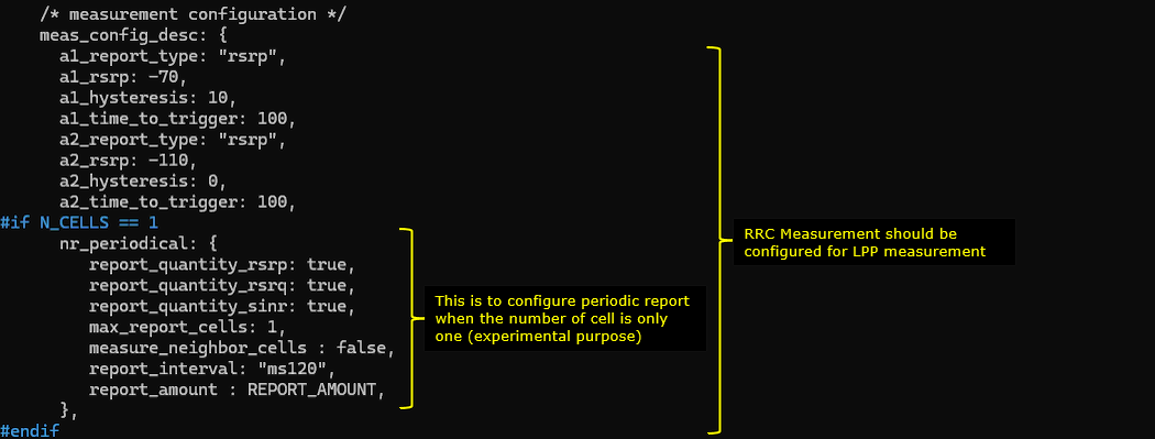
This block is the NR PRS configuration and it is used only when ENABLE_PRS is enabled. In this LPP eCID test, PRS is not used, so this section is kept as a template but remains inactive.
If you enable it, prs_resource_set defines when PRS is transmitted and how it is shaped. period, offset, time_gap, and repetition_factor control the PRS periodicity and repetition pattern. prs_muting_option1, muting_bit_repetition_factor, and prs_muting_option2 control muting so PRS can be selectively turned on and off across occasions. l_crb, rb_start, comb_size, and n_symb define the PRS frequency and time resource footprint. azimuth and elevation describe the beam direction metadata used for positioning related interpretation.
prs_resource then defines the actual PRS resources inside the set. re_offset, slot_offset, and start_symb place each PRS resource within the PRS occasion. sequence_id selects the PRS sequence identity so multiple resources can use different sequences.
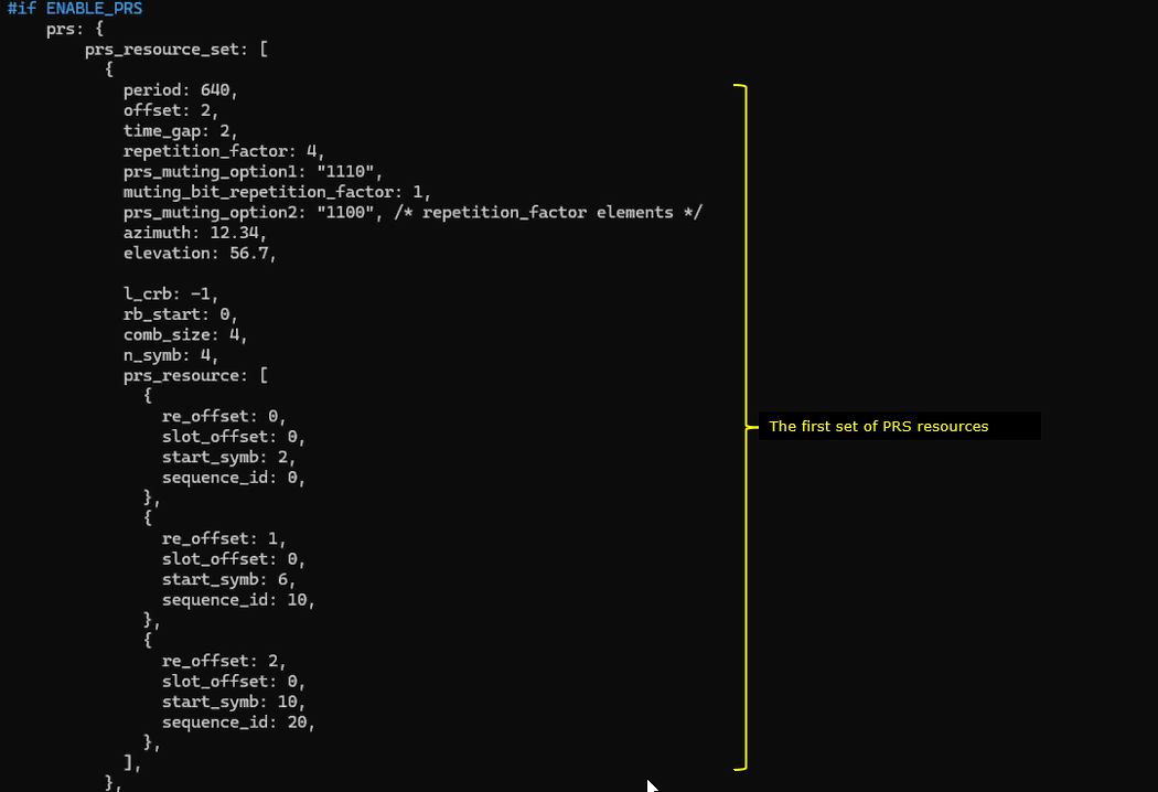
This is another PRS resource set definition. It is meant to describe a second PRS transmission pattern, but it is still under the same ENABLE_PRS condition, so it stays inactive in this eCID based LPP test.
The key parameters are period, offset, time_gap, and repetition_factor. They define how often PRS occasions appear and how many consecutive occasions are repeated. prs_muting_option1, muting_bit_repetition_factor, and prs_muting_option2 define which occasions are muted, so you can create on off patterns across the repeated PRS occasions. l_crb and rb_start define where PRS is placed in frequency, and comb_size with n_symb define the PRS density and time length.
Inside prs_resource, re_offset selects the PRS comb offset, and slot_offset and start_symb place each PRS resource inside the slot. Multiple entries let you transmit PRS in different OFDM symbols within the same PRS occasion, which is useful when you want more PRS energy or different measurement opportunities. Azimuth and elevation are metadata for the beam direction associated with this PRS set.
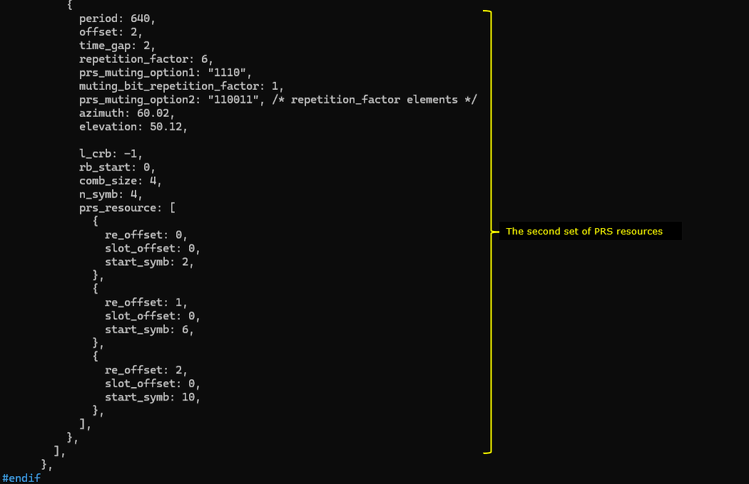
In mme-ims-nr-lpp-auto.cfg , In case where you want to use Amarisoft mme for the testing purpose without using external LMF, you can configure a test LMF with the parameter lmf_cfg.
lmf_cfg configures the internal test LMF that is embedded in the AMF. It is not a real production location server. It exists to drive and debug positioning procedures through simple APIs.
autonomous_mode controls whether the LMF runs the whole procedure by itself. If autonomous_mode is true, the LMF automatically starts the needed NRPPa and LPP exchanges when it receives a location request, so you do not need to manually call step by step APIs. If autonomous_mode is false, the LMF only sends the first trigger message and then waits for you to invoke the follow up APIs to continue.
ran_node_id_list is required when autonomous_mode is enabled. It tells the LMF which gNB to address in the HTTP request, using plmn, gnb_id_bits, and gnb_id. If this list is missing or incorrect, the autonomous procedure cannot target the right RAN node.
Perform the test
Check out the cell configuration with the command 'cell phy and cell' command, and confirm that they are configured as intended.
In cell phy, confirm that you see Cell 0x001 and Cell 0x002. Check BAND is n78 for both. Check BW is 40 MHz for both. Check DL ARFCN is 627300 for Cell 0x001 and 633300 for Cell 0x002. Check SCS is 30 kHz for both. Check the SSB section shows SSB ARFCN 626592 for Cell 0x001 and 632640 for Cell 0x002, with SCS 30 kHz.
In cell, confirm that dl_arfcn matches the DL ARFCN for each cell. Confirm pci is 500 for Cell 0x001 and 501 for Cell 0x002. Confirm plmn is 00101 and gNB_ID is 0x12345 as expected.
Switch to (mme) screen and run 'nl1' command. Make it sure that the LCS connection state is 'state=connected'.
![]()
Power on a UE in UEsim
![]()
Make it sure that the initial attach is completed properly.
Now let's send the command "nr_location_req" to Initiate the location procedure for a target UE in the AMF.
./ws.js mme '{"message": "nr_location_req","supi": "imsi-001010123456789","pei": "imei-01234567000001"}''
|
[root@CBC-2023010100 mme]# ./ws.js mme '{"message": "nr_location_req","supi": "imsi-001010123456789","pei": "imei-01234567000001"}' WebSocket remote API tool version 2024-02-16, Copyright (C) 2012-2024 Amarisoft [0.004] ### Connected to 127.0.0.1:9000 [0.004] ### Ready: name=MME, type=MME, version=2024-02-16 [0.024] <== Send message nr_location_req id#1 [0.035] ==> Message received { "message": "nr_location_req", "message_id": "id#1", "time": 229.742, "utc": 1708232748.754 } |
Log Analysis
This message is the UE�s 5GMM Registration Request sent to the network during the initial registration procedure. In this NAS message the UE reports its supported capabilities to the network.
In the decoded capability section, the field LPP = 1 indicates that the UE supports the LPP positioning protocol. By including this information in the Registration Request, the UE informs the network that it is capable of participating in LPP based positioning procedures. This allows the network to later deliver LPP messages to the UE when positioning operations are initiated.
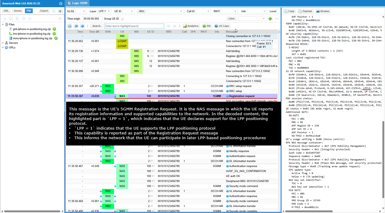
This message shows the gNB sending an RRC Reconfiguration message to the UE to configure measurement parameters. This configuration tells the UE which NR cell and signals it should measure and how the measurement results should be processed.
The configuration includes a measurement object for an NR cell. The parameter measObjectNR indicates that the measurement target is an NR cell. The ssbFrequency parameter specifies the carrier frequency where the UE should perform the measurements. The ssbSubcarrierSpacing parameter defines the SSB subcarrier spacing used for the measurement signals. The smtc1 field defines the SSB measurement timing configuration that determines when the UE should monitor SSB transmissions.
The referenceSignalConfig section indicates that the measurement is based on SSB reference signals. The quantityConfigIndex and quantityConfig parameters define the filtering configuration used when calculating measurement quantities such as RSRP or RSRQ. The measGapConfig release field indicates that no measurement gap is configured in this message.
Overall, this message configures the UE to monitor the specified NR cell and perform radio measurements according to the parameters provided by the gNB. These measurements can later be used by the network for procedures such as mobility management or positioning.
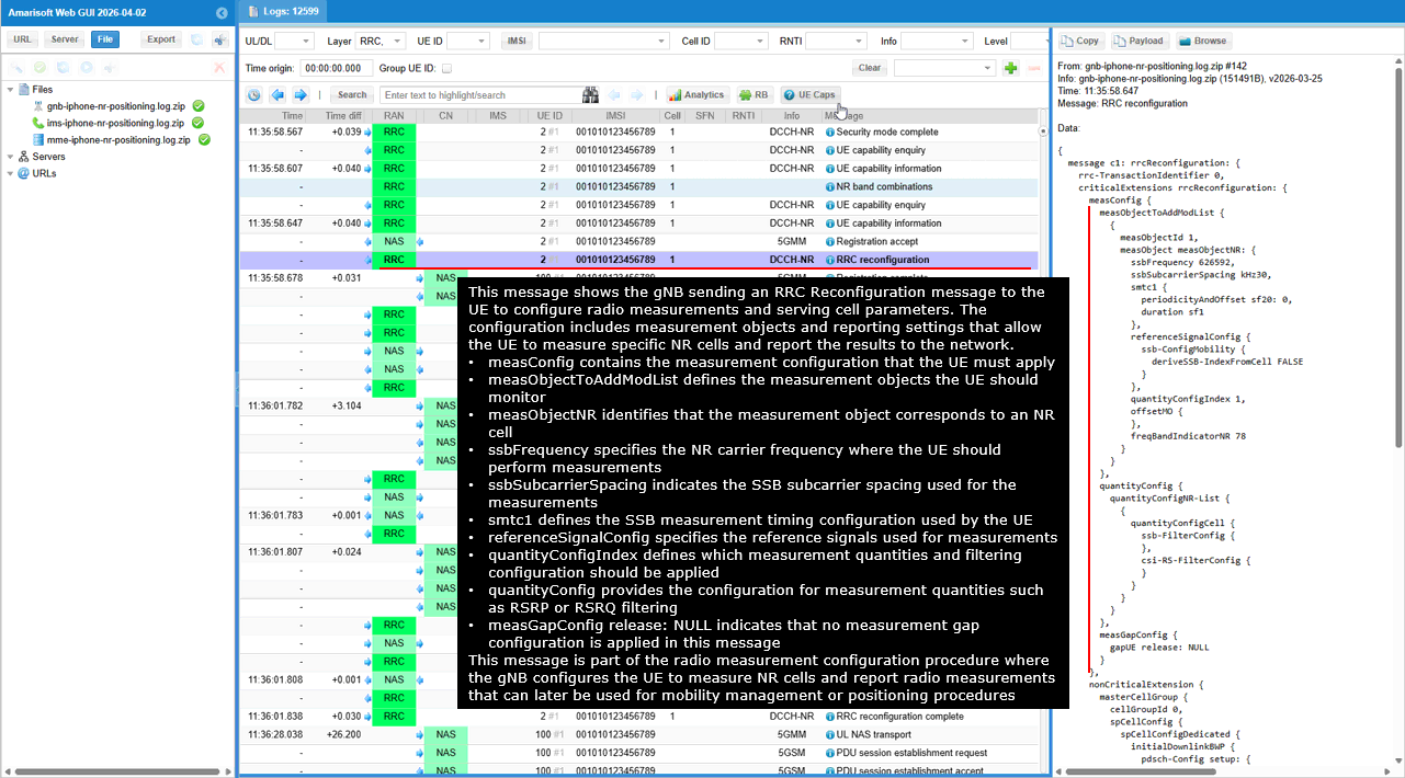
This message shows the UE sending a SIP INVITE message to the IMS network to initiate a call session. The request is sent from the UE toward the IMS core through the P-CSCF and is used to establish a voice call.
This SIP INVITE represents the call setup phase of an IMS voice session. In many commercial implementations, LPP based positioning procedures are often triggered only when the UE is in an emergency call, which is why the positioning related signaling may appear during this type of call scenario.
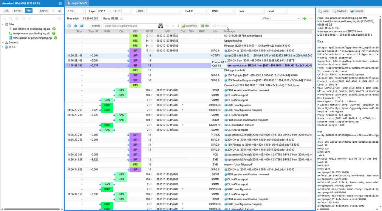
This message shows the AMF sending an HTTP POST request to the location service through the Nlmf interface to trigger a location determination procedure for the UE. The request asks the Location Management Function to calculate the position of the UE based on the information provided by the AMF.
The path /nlmf-loc/v1/determine-location indicates that the AMF is requesting the LMF to start a location determination procedure. The parameter supi identifies the target UE for which the location is being requested. The fields ngci and nrCellId provide the serving NR cell information that can be used as the starting reference for the positioning procedure.
The message also includes the UE capability information. The field lppSupport: true indicates that the UE supports the LPP protocol. This allows the LMF to perform LPP based positioning procedures by sending LPP messages to the UE through the AMF.
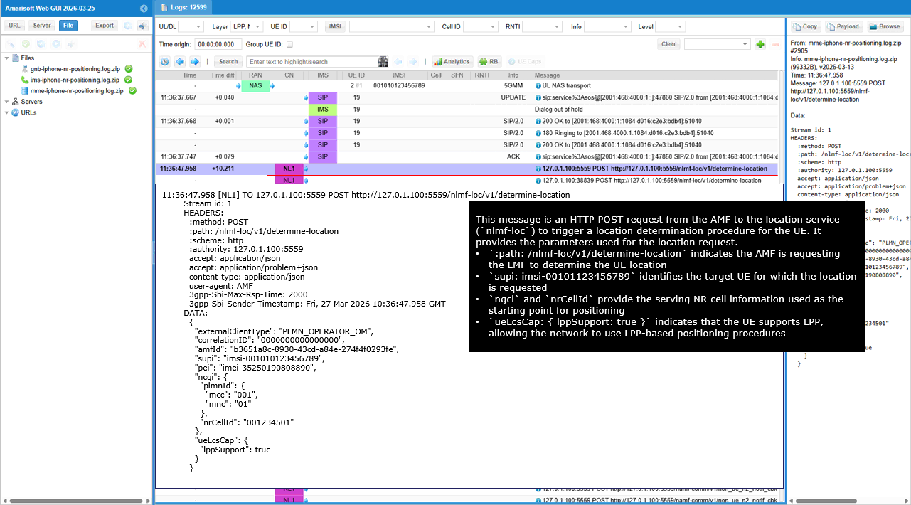
This message shows the LMF receiving the location determination request sent by the AMF. The request is delivered through the Nlmf interface using an HTTP POST message to trigger the UE location determination procedure.
The path /nlmf-loc/v1/determine-location indicates that the request is asking the LMF to determine the location of the UE. The field supi identifies the UE whose location is being requested. The parameters ngci and nrCellId provide the serving NR cell information that can be used as the starting reference for the positioning procedure.
The message also includes the UE capability information. The field lppSupport: true indicates that the UE supports the LPP protocol. Based on this capability, the LMF can initiate LPP based positioning procedures and exchange positioning messages with the UE through the AMF.
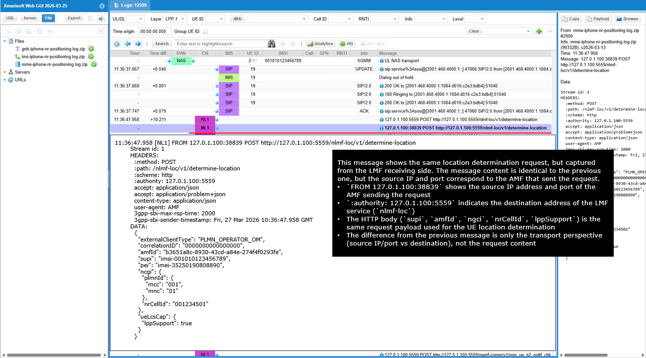
This message shows the LMF sending an HTTP POST request to the AMF to create a subscription for N2 related messages for the UE. The purpose of this request is to allow the LMF to receive notifications when relevant NGAP or NRPPa signaling related to positioning occurs for the UE.
The path /namf-comm/v1/non-ue-n2-messages/subscriptions indicates that the LMF is requesting the AMF to create a subscription for N2 messages. The field anTypeList set to 3GPP_ACCESS indicates that the subscription applies to the 3GPP radio access network. The parameter n2InformationClass set to NRPPa specifies that the subscription is related to NR positioning signaling.
The field n2NotifyCallbackUri provides the callback address where the AMF will send notifications when matching N2 messages are detected. This allows the LMF to receive NRPPa related signaling events that may be required for the positioning procedure.
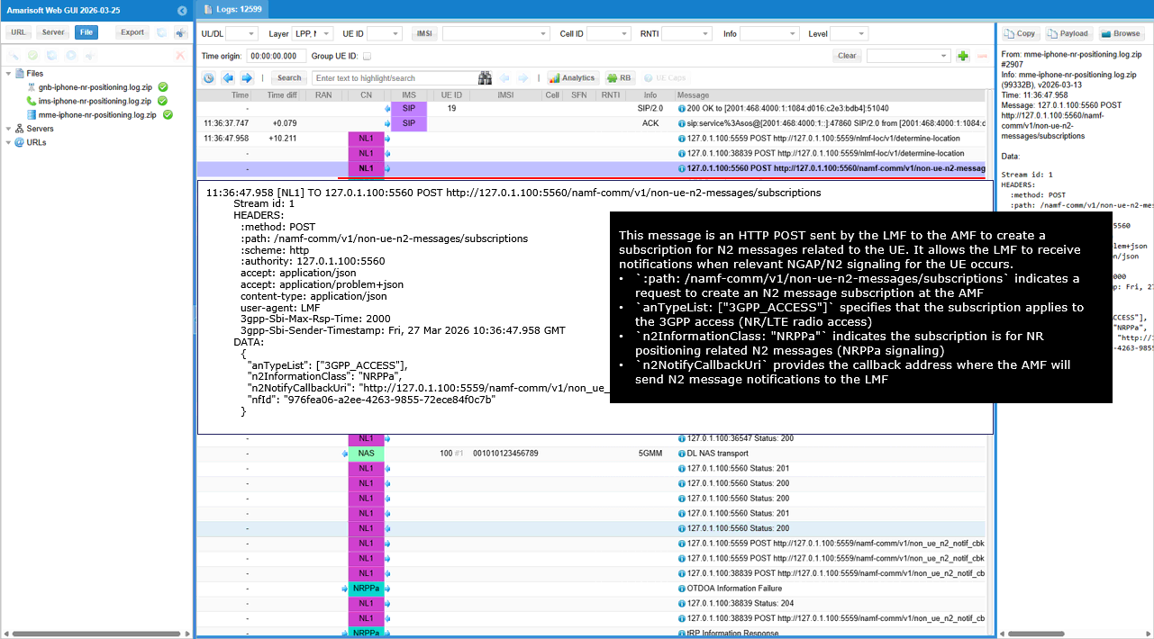
This message shows the LMF sending an NRPPa OTDOA Information Request to the gNB to obtain the configuration and reference signal information required for OTDOA positioning. The request belongs to the OTDOAInformationExchange procedure, which is used by the LMF to collect radio configuration details from the gNB before starting UE positioning measurements.
The request asks the gNB to provide several parameters related to the serving cell and PRS configuration. The parameters pci, cgi, and tac identify the reference cell and its global identity information. The fields earfcn and dlBandwidth indicate the carrier frequency and bandwidth used by the cell.
The request also asks for PRS related configuration information used for OTDOA measurements. Parameters such as prsBandwidth, prsConfigIndex, numDLFrames, prsFrequencyHoppingConfig, and prsMutingConfiguration describe how the PRS signals are transmitted. Additional fields such as cpLength, noAntennaPorts, and sfnInitTime provide timing and transmission characteristics needed for accurate OTDOA timing measurements.
The request further includes parameters such as ng-RANAccessPointPosition and prsid, which provide the gNB location and PRS identification information used by the LMF when calculating the UE position. These parameters allow the LMF to understand the exact PRS transmission configuration and the physical position of the transmitting cell, which are essential inputs for OTDOA based positioning calculations.
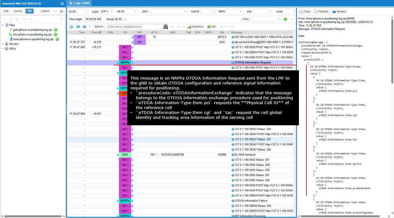
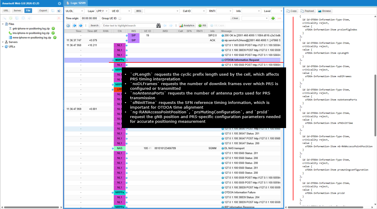
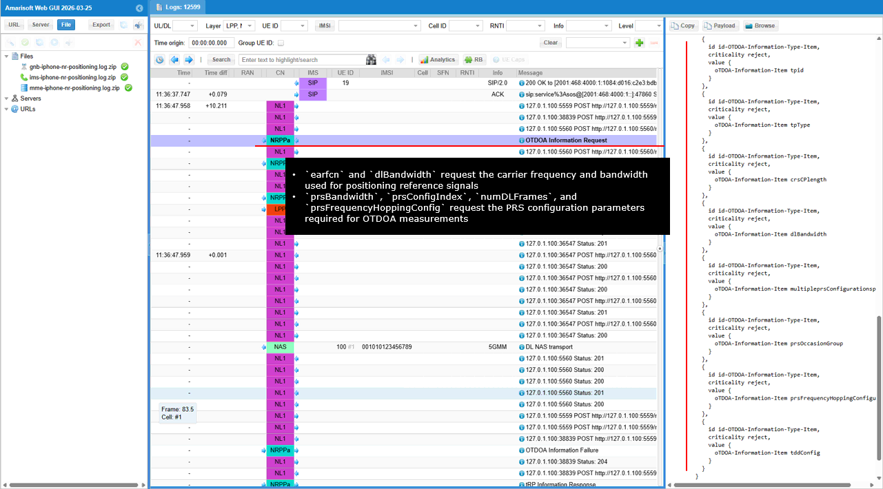
This message shows the LMF sending an HTTP POST request to the AMF to transfer an NRPPa positioning message toward the gNB through the N2 interface. The request instructs the AMF to forward the NRPPa message to the target gNB.
The path /namf-comm/v1/non-ue-n2-messages/transfer indicates that the LMF is requesting the AMF to deliver an N2 message to a specific gNB. The field globalRanNodeList identifies the target gNB using the PLMN ID and the gNB identifier. The parameter n2InformationClass set to NRPPa indicates that the message being delivered is related to NR positioning signaling.
The payload contained in ngapData carries the NRPPa protocol message that will be forwarded by the AMF to the gNB over the NGAP interface. Through this message the LMF delivers the NRPPa positioning request to the gNB so that the required positioning information can be collected.
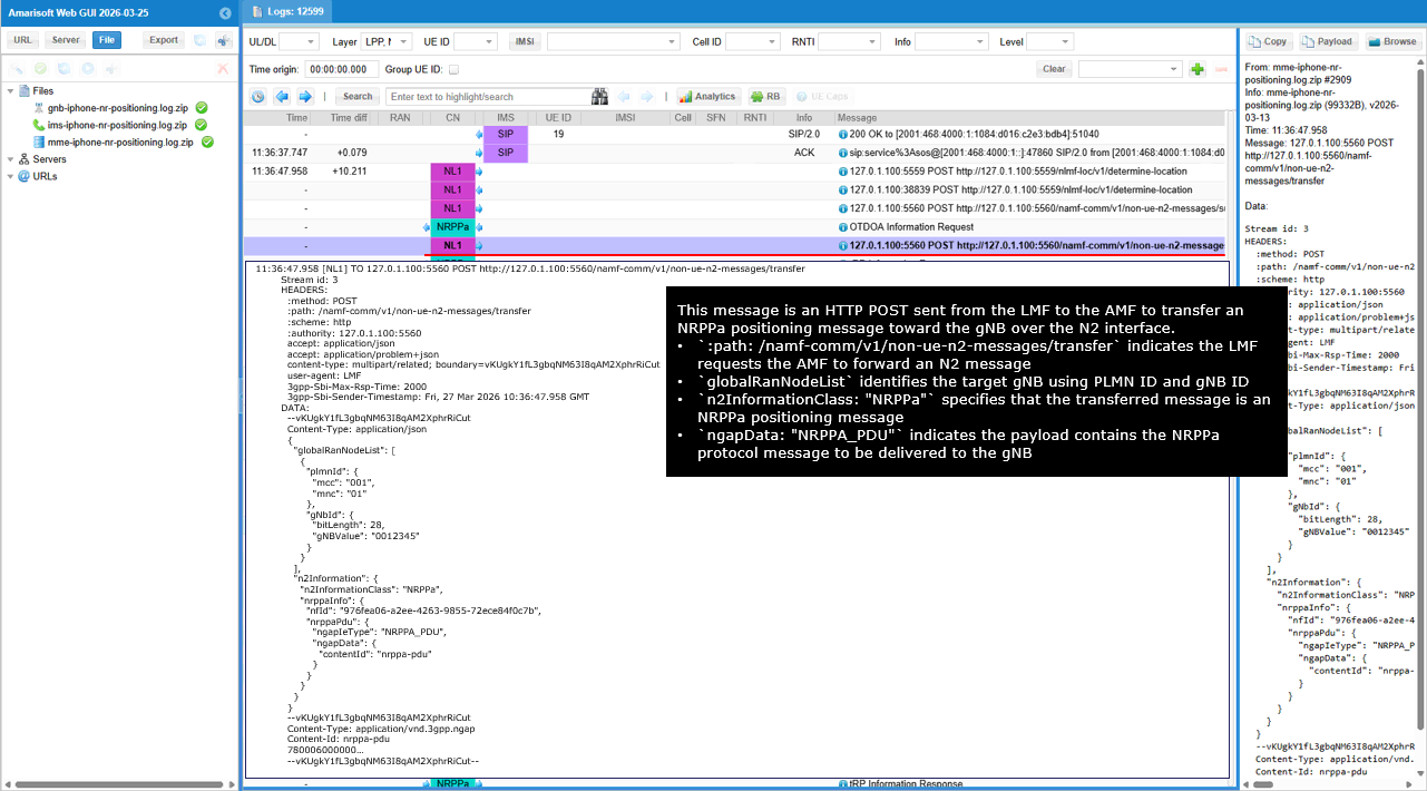
This message shows an NRPPa TRP Information Request sent from the LMF to the gNB to obtain information about the Transmission Reception Point used for positioning. The request belongs to the TRPInformationExchange procedure used in NR positioning.
The request asks the gNB to provide several parameters describing the TRP and its transmission configuration. The fields mPCI and ng-RAN-CGI request the physical cell identity and the global cell identity of the TRP. The parameter arfcn identifies the carrier frequency used by the cell.
The message also requests PRS related configuration information through the prsConfig parameter. Additional fields such as ssbInfo and sfnInitTime provide SSB related configuration and timing information required for positioning synchronization.
The parameters geoCoord and spatialDirectionInfo request the physical location and spatial characteristics of the TRP. This information allows the LMF to understand the position and transmission properties of the TRP, which are required inputs for calculating the UE position during the positioning procedure.
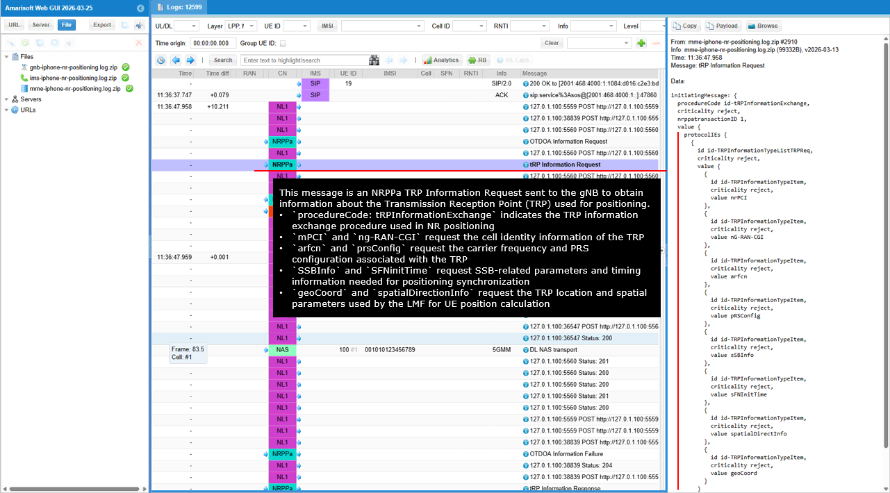
This message shows the LMF sending an HTTP POST request to the AMF to transfer the NRPPa TRP Information Request toward the gNB through the N2 interface. The request instructs the AMF to forward the NRPPa message to the target gNB.
The path /namf-comm/v1/non-ue-n2-messages/transfer indicates that the LMF is requesting the AMF to deliver an N2 message. The field globalRanNodeList identifies the target gNB using the PLMN ID and the gNB identifier. The parameter n2InformationClass set to NRPPa indicates that the transferred message belongs to NR positioning signaling.
The payload contained in ngapData carries the NRPPa protocol message that includes the TRP Information Request. The AMF forwards this message to the gNB over the NGAP interface so that the gNB can provide the TRP related information required for the positioning procedure.
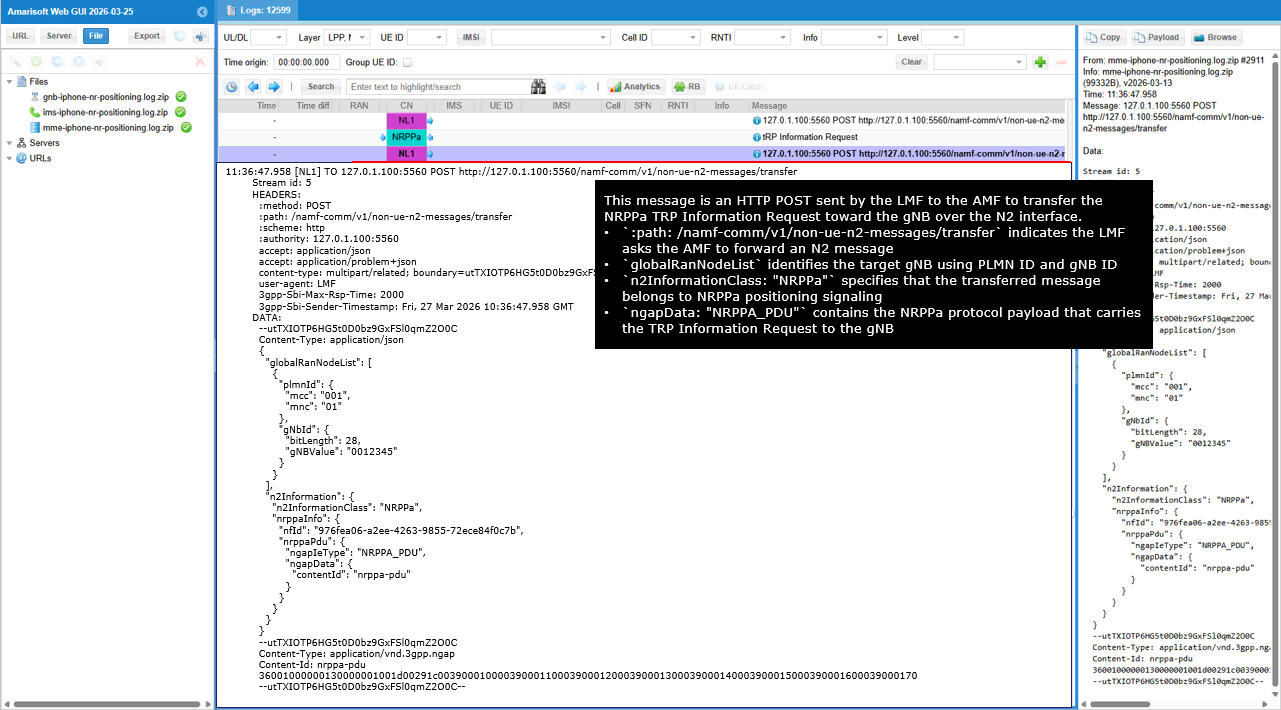
This message shows the LMF sending an HTTP POST request to the AMF to create a UE specific N1/N2 message subscription for positioning procedures. The subscription allows the LMF to receive notifications related to positioning messages exchanged with the UE.
The path /namf-comm/v1/ue-contexts/.../n1-n2-messages/subscriptions indicates that the LMF is requesting the AMF to create a subscription associated with the UE context. The parameter n2InformationClass set to NRPPa indicates that the subscription applies to NRPPa positioning signaling over the N2 interface.
The field n1MessageClass set to LPP indicates that LPP messages carried over the N1 interface are also included in the subscription. The parameters n2NotifyCallbackUri and n1NotifyCallbackUri provide the callback addresses where the AMF will send notifications when corresponding N2 or N1 messages related to the UE are detected.
The field imei identifies the UE for which the subscription is created, allowing the LMF to receive positioning related signaling events associated with that specific UE.
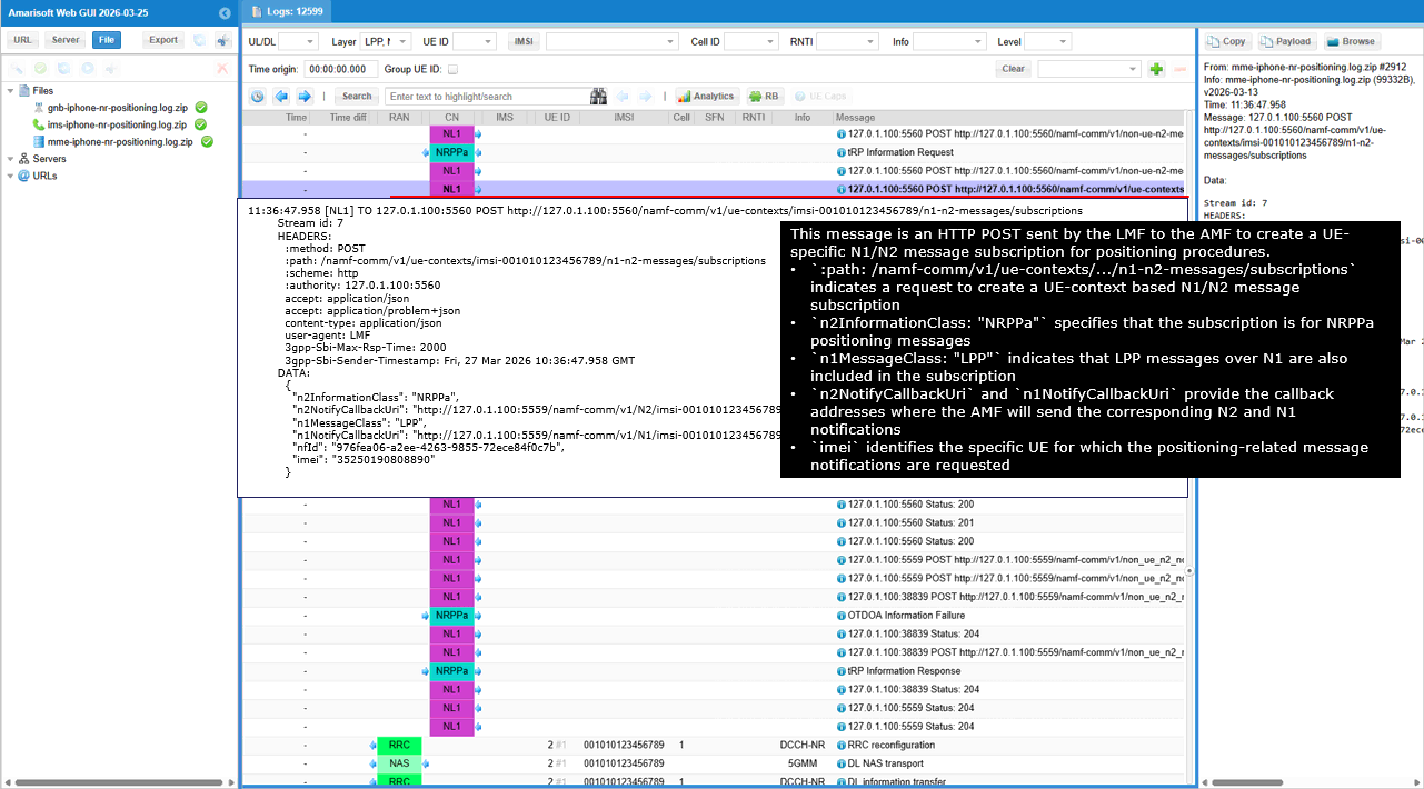
This message shows the LMF sending an LPP RequestCapabilities message to the UE to obtain the UE�s supported positioning capabilities. The message asks the UE to report which positioning methods and measurement types it supports.
This message also initiates an E-CID measurement procedure. The procedure code eCIDMeasurementInitiation indicates that the network is starting an E-CID based positioning measurement session. The parameter LMF-UE-Measurement-ID identifies the measurement session created by the LMF.
The field reportCharacteristics set to onDemand indicates that the measurements are requested only when triggered by the network. The parameter measurementQuantities lists the measurement types that the UE should provide.
The requested measurements include cell-ID and angleOfArrival for identifying the serving cell and estimating the signal arrival direction. The parameters timingAdvanceType1 and timingAdvanceType2 request UE timing advance measurements. The fields RSRP and RSRQ request LTE signal strength and quality measurements, while ss-RSRP and ss-RSRQ request NR synchronization signal measurements. Additional measurements such as csi-RSRP and csi-RSRQ request CSI based NR measurements used for positioning analysis.
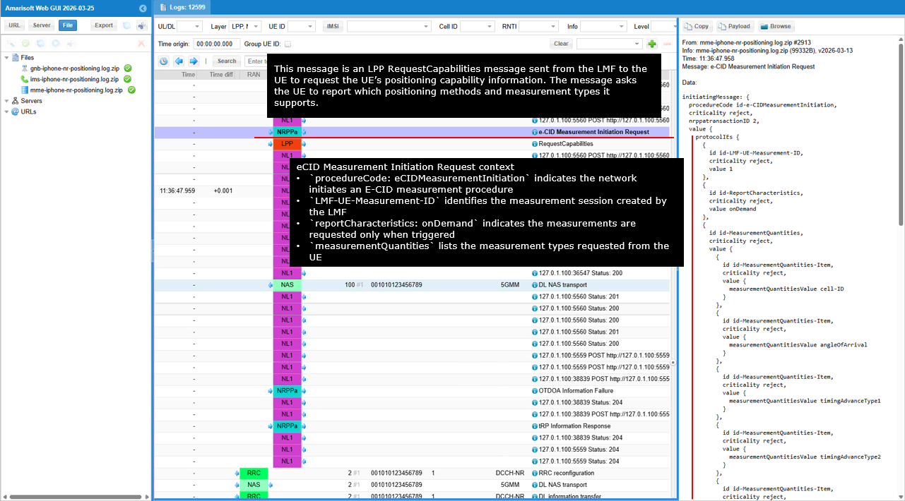
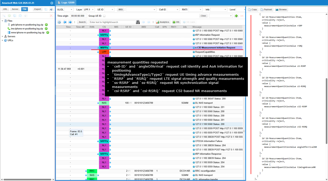
This message shows an LPP RequestCapabilities message sent from the LMF to the UE to request the UE�s supported positioning capabilities. This message begins an LPP transaction between the LMF and the UE.
The field transactionNumber identifies the LPP transaction used to correlate the request and the corresponding response. The requestCapabilities field asks the UE to report which positioning methods and measurement capabilities it supports.
The parameter gnss-SupportListReq requests the UE to report its supported GNSS capabilities. The fields otdoa-RequestCapabilities and ecid-RequestCapabilities request information about the UE�s support for OTDOA and E-CID based positioning methods. Through this message the LMF collects the UE capability information needed to determine which positioning techniques can be used for the positioning procedure.
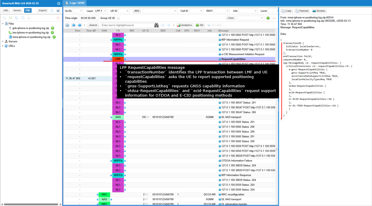
This message shows the LMF sending an HTTP POST request to the AMF to deliver positioning related messages toward both the UE and the gNB. The request uses the UE context to send combined N1 and N2 messages for the positioning procedure.
The path /namf-comm/v1/ue-contexts/.../n1-n2-messages indicates that the LMF is asking the AMF to forward messages through both the N1 and N2 interfaces. The n1MessageContainer contains the message that will be delivered to the UE, where the field n1MessageClass set to LPP indicates that the message carried over N1 is an LPP positioning message.
The n2InfoContainer carries the message that will be delivered to the gNB. The parameter n2InformationClass set to NRPPa indicates that the N2 message belongs to NRPPa positioning signaling. The ngapData field contains the NRPPa protocol payload that will be forwarded to the gNB over the NGAP interface.
The field n1n2FailureTxfNotifURI provides the callback address that the AMF will use to notify the LMF if the delivery of the N1 or N2 messages fails. Through this request the LMF triggers both the UE side LPP signaling and the gNB side NRPPa signaling required for the positioning procedure.
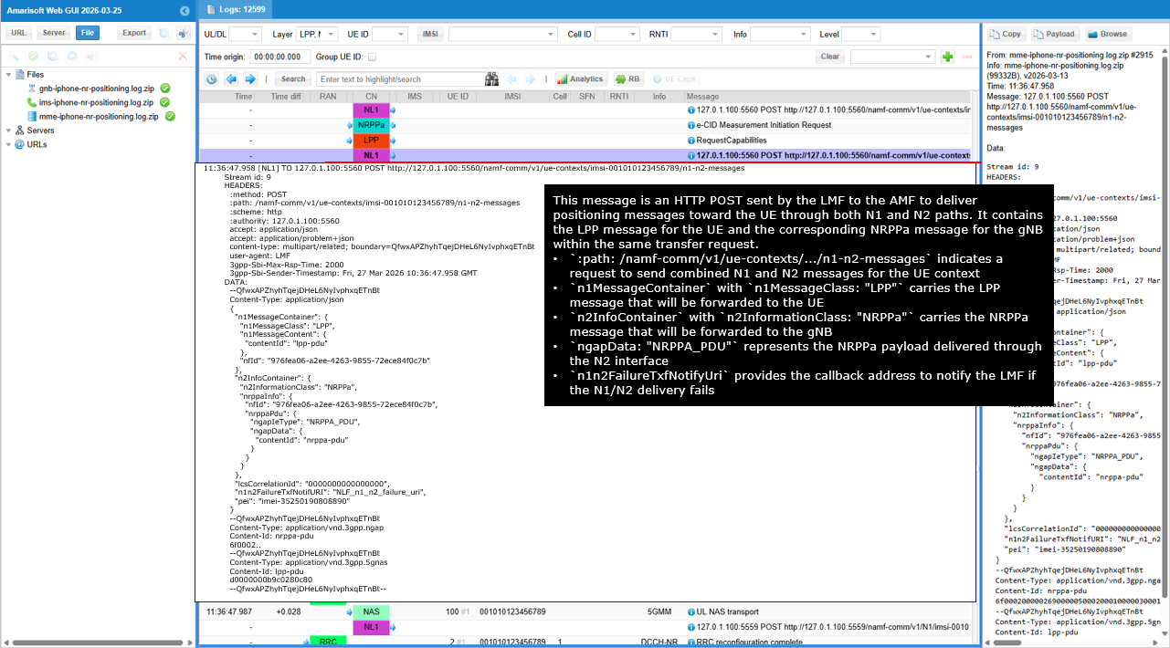
This message shows the LMF sending an HTTP POST request to the AMF to create a subscription for receiving N2 positioning related messages for the UE. This allows the LMF to be notified when relevant positioning signaling occurs over the N2 interface.
The path /namf-comm/v1/non-ue-n2-messages/subscriptions indicates that the LMF is requesting the AMF to create an N2 message subscription. The parameter anTypeList set to 3GPP_ACCESS indicates that the subscription applies to the 3GPP radio access network.
The field n2InformationClass set to NRPPa specifies that the subscription is related to NRPPa positioning signaling. The parameter n2NotifyCallbackUri provides the callback address where the AMF will send notifications when matching N2 positioning messages are detected.
The field nfId identifies the LMF instance that registered the subscription so that the AMF knows which network function should receive the notification messages.
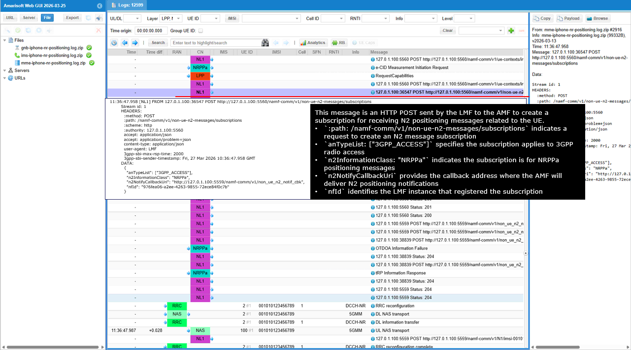
This message shows the HTTP response from the AMF confirming the creation of the N2 message subscription requested earlier by the LMF. The response indicates that the subscription resource has been successfully created.
The status value 201 indicates that the subscription creation request was successfully processed. The Location header provides the URI of the newly created subscription resource at /namf-comm/v1/non-ue-n2-messages/subscriptions/....
The field n2NotifySubscriptionId is the identifier assigned by the AMF for this N2 notification subscription. This identifier will be used by the AMF when sending N2 positioning related notifications such as NRPPa messages to the LMF during the positioning procedure.
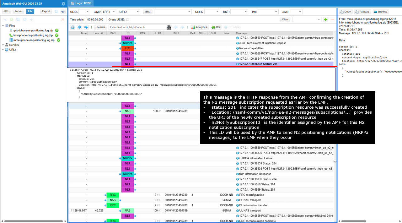
This message shows the LMF sending an HTTP POST request to the AMF to transfer an NRPPa positioning message toward the gNB over the N2 interface. The request instructs the AMF to forward the NRPPa message to the target gNB.
The path /namf-comm/v1/non-ue-n2-messages/transfer indicates that the LMF is requesting the AMF to deliver an N2 message. The field globalRanNodeList identifies the target gNB using the PLMN ID and the gNB identifier.
The parameter n2InformationClass set to NRPPa indicates that the transferred message belongs to NR positioning signaling. The field ngapData contains the NRPPa protocol payload that will be forwarded by the AMF to the gNB.
The binary payload with content type application/vnd.3gpp.ngap carries the actual NRPPa message encapsulated in NGAP format for delivery over the N2 interface to the gNB.
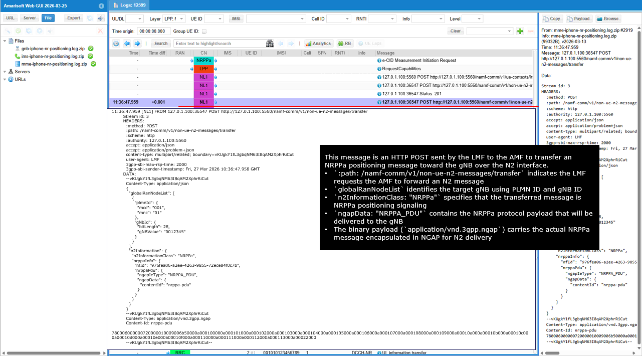
This message shows the HTTP response from the AMF confirming that the N2 message transfer request has been accepted. The request was previously sent by the LMF to forward an NRPPa positioning message to the gNB.
The status value 200 indicates that the request has been successfully processed by the AMF. The result field N2_INFO_TRANSFER_INITIATED indicates that the AMF has started the procedure to forward the N2 message to the gNB.
This response confirms that the NRPPa message transfer procedure has been initiated on the N2 interface. After this step, the actual NRPPa message will be delivered to the gNB through NGAP signaling.
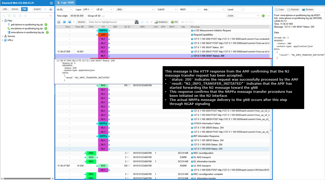
This message shows the LMF sending an HTTP POST request to the AMF to transfer an NRPPa eCID Measurement Initiation Request toward the gNB over the N2 interface. The request instructs the AMF to forward the NRPPa positioning message to the target gNB.
The path /namf-comm/v1/non-ue-n2-messages/transfer indicates that the LMF is requesting the AMF to deliver an N2 message. The field globalRanNodeList identifies the target gNB using the PLMN ID and the gNB identifier.
The parameter n2InformationClass set to NRPPa indicates that the transferred message belongs to NR positioning signaling. The field ngapData carries the NRPPa protocol payload that contains the eCID Measurement Initiation Request.
The binary payload with content type application/vnd.3gpp.ngap contains the encoded NRPPa message that will be forwarded by the AMF to the gNB over the NGAP interface.
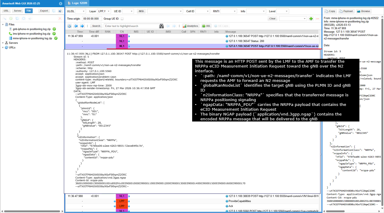
This message shows the HTTP response from the AMF confirming that the N2 message transfer request has been accepted and started.
The status value 200 indicates that the AMF successfully processed the request. The result N2_INFO_TRANSFER_INITIATED indicates that the AMF has initiated forwarding of the N2 message toward the gNB.
This message is only an acknowledgement. The actual NRPPa positioning payload was already carried in the earlier HTTP POST transfer request sent by the LMF.
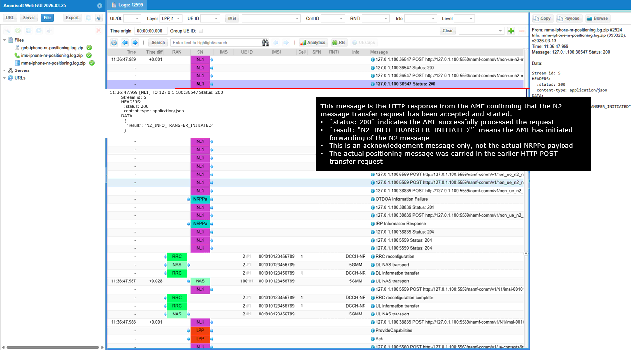
This message shows the LMF sending an HTTP POST to the AMF to create a subscription for receiving notifications related to N2 positioning messages for the specific UE.
The method POST indicates that the LMF is creating a new subscription resource. The path /namf-comm/v1/ue-contexts/imsi-001010123456789/n1-n2-messages/subscriptions specifies the subscription API under the UE context.
The parameter n2InformationClass set to NRPPa indicates that the subscription is for NR positioning signaling over the N2 interface. The parameter n1MessageClass set to LPP indicates that the subscription also covers LPP messages toward the UE.
The field n1NotifyCallbackUri specifies the URI where the AMF will send notifications when an N1 message event occurs. The field n2NotifyCallbackUri specifies the URI where the AMF will send notifications when an N2 message event occurs.
The field nfId identifies the LMF network function instance that created the subscription, and the field imei identifies the UE device associated with this subscription.
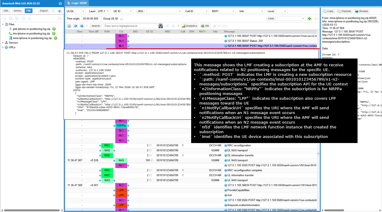
This message shows the HTTP response from the AMF confirming that the N1/N2 notification subscription requested by the LMF has been successfully created.
The status value 201 indicates that a new subscription resource has been successfully created. The Location header provides the URI of the created subscription resource under the UE context.
The parameter n1n2NotifySubscriptionId is the identifier assigned by the AMF for this subscription. This ID will be used by the AMF when sending notifications related to N1 or N2 messages for this UE.
This subscription allows the AMF to notify the LMF when relevant N1 or N2 signaling events related to the UE occur.
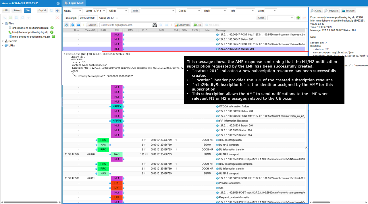
This message shows the LMF sending an HTTP POST request to the AMF to deliver both an N1 (LPP) message to the UE and an N2 (NRPPa) message to the gNB as part of the positioning procedure.
The method POST indicates that the LMF is requesting the AMF to trigger delivery of N1 and N2 messages. The path /namf-comm/v1/ue-contexts/imsi-001010123456789/n1-n2-messages specifies the API used to deliver N1/N2 messages for the UE context.
The field n1MessageClass set to LPP indicates that the N1 message sent to the UE carries positioning signaling. The parameter n1MessageContent contains the LPP PDU that will be delivered to the UE through NAS signaling.
The field n2InformationClass set to NRPPa indicates that the N2 message carries NR positioning signaling toward the gNB. The parameter ngapData represents the NRPPa message encoded inside NGAP for delivery over the N2 interface.
The field nfId identifies the LMF network function instance initiating the request, and the field imei identifies the UE associated with this positioning procedure.
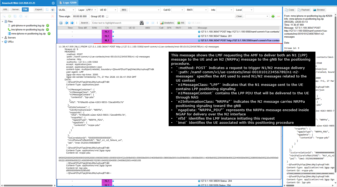
This message shows the HTTP response from the AMF confirming that the request to deliver both N1 and N2 messages has been accepted and the transfer procedure has started.
The status value 200 indicates that the AMF successfully processed the request. The field cause set to N1_N2_TRANSFER_INITIATED indicates that the AMF has initiated forwarding of the N1 message to the UE and the N2 message to the gNB.
This message is an acknowledgement of the N1N2MessageTransfer request sent earlier by the LMF. The actual LPP (N1) and NRPPa (N2) messages were included in the previous HTTP POST request.
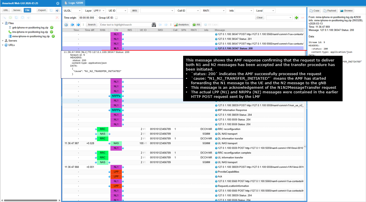
This message shows the AMF delivering an LPP positioning message to the UE through NAS using the DL NAS Transport procedure.
The message type DL NAS transport indicates that the network is sending a NAS container toward the UE. The payload container type 3 (LTE Positioning Protocol) indicates that the NAS message carries an LPP positioning message.
The field transactionID identifies the LPP positioning transaction initiated by the location server (LMF). The parameter initiator = locationServer indicates that the positioning procedure was started by the network.
The field requestCapabilities requests the UE to report its supported positioning capabilities. The parameter gnss-SupportListReq asks the UE to report the GNSS positioning capabilities it supports. The field assistanceDataSupportListReq requests information about the assistance data supported by the UE.
The parameter locationVelocityTypesReq asks the UE which location and velocity estimation types it supports. The field otdoa-RequestCapabilities requests OTDOA positioning capability information. The field ecid-RequestCapabilities requests E-CID positioning capability information. The field nr-DL-TDOA-RequestCapabilities-r16 requests NR DL-TDOA positioning capability information.
This message is part of the LPP capability exchange phase of the positioning procedure.
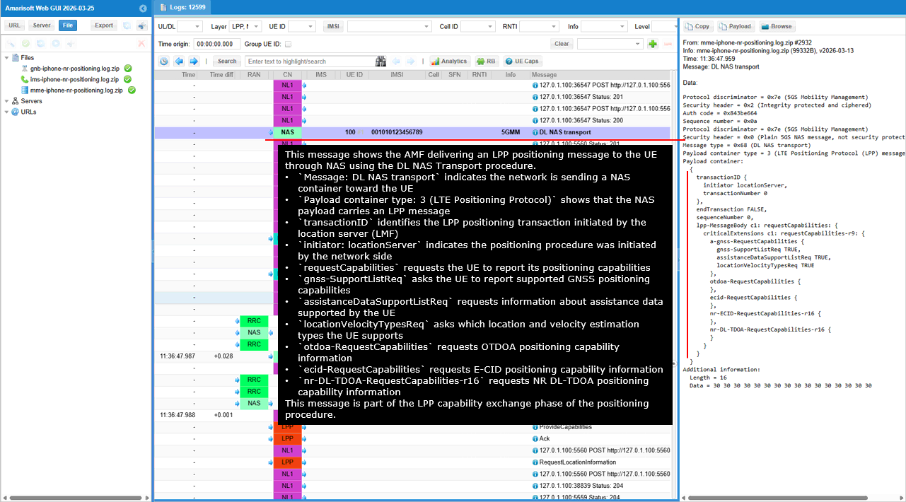
This message shows the gNB sending an RRCReconfiguration to the UE to configure measurement reporting required for the positioning procedure.
The message RRCReconfiguration indicates that the gNB is updating the UE RRC configuration. The field reportConfigToAddModList defines new measurement reporting configurations used for positioning measurements.
reportConfigId 1 configures periodic reporting based on SSB measurements. The field rsType = ssb indicates that the measurements use SSB signals. The parameter reportInterval = ms120 sets the reporting period to 120 ms. The field reportQuantityCell enables reporting of RSRP and RSRQ. The parameter maxReportCells = 1 limits reporting to the strongest cell.
reportConfigId 2 configures periodic reporting based on CSI-RS measurements. The field rsType = csi-rs indicates measurements based on CSI-RS resources.
The field measIdToAddModList links measurement objects to the reporting configurations. measId 1 uses reportConfigId 1 for SSB measurements, and measId 2 uses reportConfigId 2 for CSI-RS measurements.
This configuration prepares the UE to periodically report radio measurements that will be used by the network for positioning.
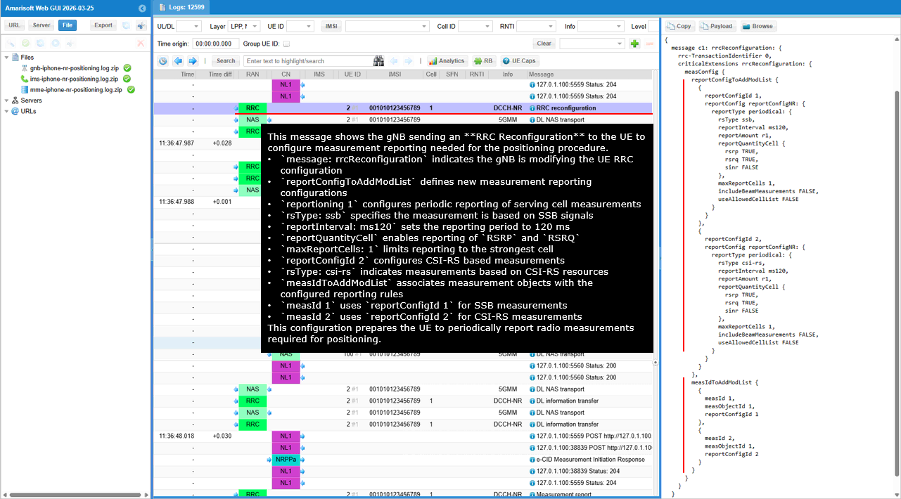
This message shows the AMF sending an LPP positioning message to the UE using the DL NAS Transport procedure. The AMF sends DL NAS Transport to the UE to carry the LPP message over NAS signaling. The payload container type indicates LTE Positioning Protocol, meaning that the NAS container carries an LPP message generated by the location server.
The LPP message contains a transactionID that identifies the positioning transaction started by the location server. The initiator is set to locationServer, which indicates that the positioning procedure was initiated by the LMF on the network side.
The requestCapabilities element asks the UE to report its supported positioning capabilities. The gnss-SupportListReq requests the UE to report which GNSS positioning methods it supports. The assistanceDataSupportListReq requests the UE to report which assistance data types it can process. The locationVelocityTypesReq asks the UE to report the supported location and velocity estimation types.
The message also includes requests for several positioning methods supported by the network. The otdoa-RequestCapabilities asks the UE to report its OTDOA positioning capability. The ecid-RequestCapabilities asks the UE to report its E-CID positioning capability. The nr-DL-TDOA-RequestCapabilities-r16 asks the UE to report its NR DL-TDOA positioning capability. This message therefore starts the LPP capability exchange procedure between the LMF and the UE.
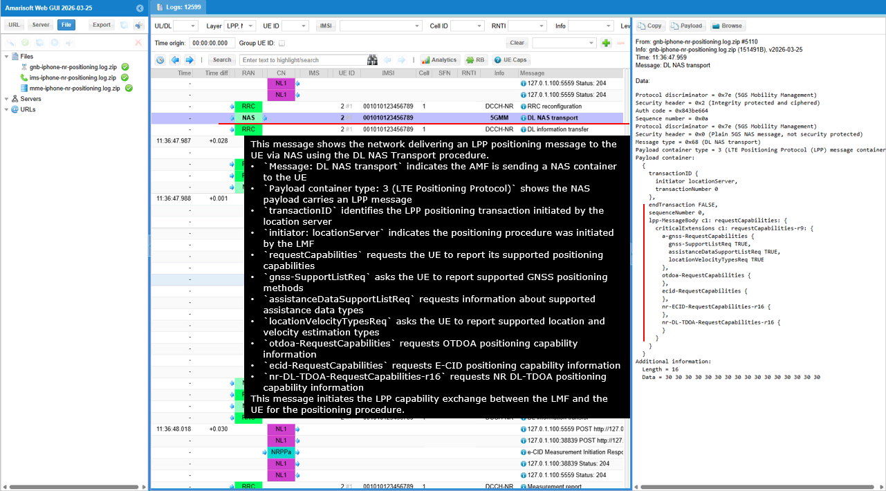
This message shows the UE sending an LPP positioning message back to the network using the UL NAS Transport procedure. The UE sends UL NAS Transport to the network to carry the LPP message through NAS signaling. The payload container type indicates LTE Positioning Protocol, which means the NAS container carries an LPP message.
The transactionID and transactionNumber correspond to the earlier positioning transaction initiated by the location server. The initiator is locationServer, which indicates that this message is a response to the capability request previously sent by the LMF.
The provideCapabilities element indicates that the UE is reporting its supported positioning capabilities. The gnss-SupportList shows that the UE supports GNSS positioning, including GPS, and the gnss-SignalIDs field indicates the GNSS signal types supported by the UE.
The assistanceDataSupportList indicates which GNSS assistance data types the UE can process. The locationCoordinateTypes field indicates the coordinate formats supported by the UE for location reporting. The velocityTypes field indicates the velocity reporting formats supported by the UE.
The nr-ECID-ProvideCapabilities-r16 element indicates that the UE supports NR E-CID positioning measurements. This message therefore provides the UE positioning capability information in response to the earlier LPP RequestCapabilities message sent by the location server.
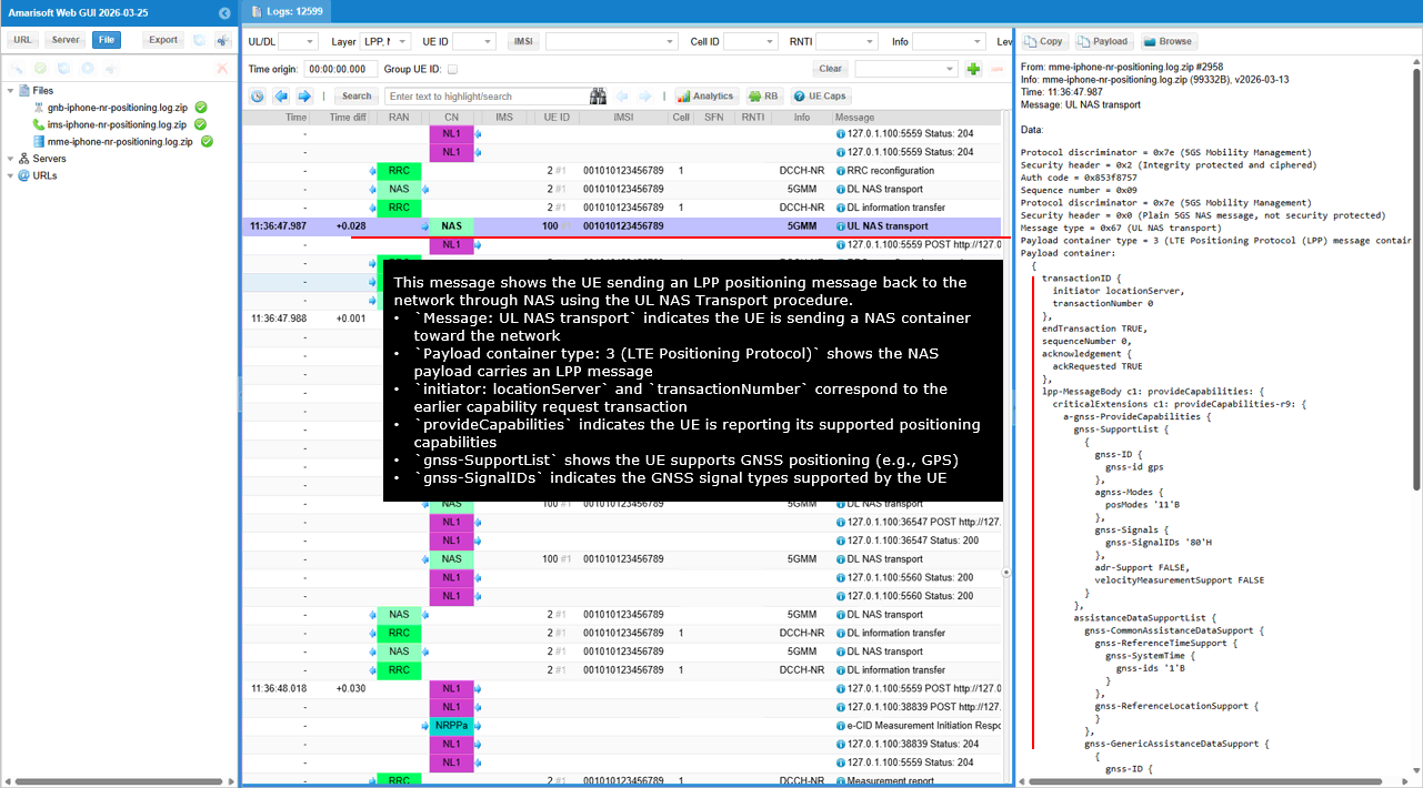
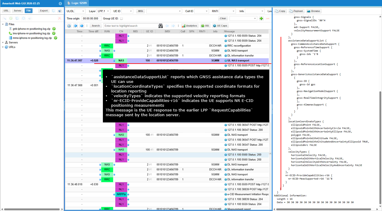
This message shows the AMF notifying the LMF that an N1 message from the UE has been received and delivered through the N1 interface. The AMF sends this notification because the LMF previously created an N1/N2 notification subscription for this UE.
The method POST indicates that the AMF is sending a notification to the LMF. The path /namf-comm/v1/n1/imsi-001010123456789/notify/imei-35250190808890 indicates the notification API used by the AMF to report an N1 message delivery event.
The field n1NotifySubscriptionId identifies the subscription that was previously created by the LMF. The parameter n1MessageClass is set to LPP, which indicates that the received N1 message contains LPP positioning signaling.
The field contentId references the LPP message payload included in the multipart body of the notification. The field nfId identifies the AMF instance sending the notification.
The fields plmnId, amfId, and nrCellId provide the serving network and cell information associated with the UE. The field imei identifies the UE involved in the positioning procedure.
This notification informs the LMF that the UE has sent an LPP message through UL NAS Transport and that the message has been delivered through the N1 interface for the ongoing positioning transaction.
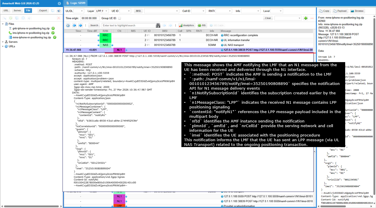
This message shows the UE sending an LPP ProvideCapabilities message to the network in response to the earlier capability request from the location server. The message ProvideCapabilities indicates that the UE is reporting its supported positioning capabilities. The transactionID matches the earlier RequestCapabilities transaction initiated by the location server. The endTransaction flag set to TRUE indicates that the UE completes the capability exchange procedure for this transaction.
The gnss-SupportList indicates that the UE supports GNSS positioning such as GPS, and the gnss-SignalIDs field indicates the GNSS signal types supported by the UE. The assistanceDataSupportList reports the types of GNSS assistance data that the UE can use. The locationCoordinateTypes field specifies the coordinate formats supported by the UE for location reporting. The velocityTypes field specifies the velocity reporting formats supported by the UE. The nr-ECID-ProvideCapabilities-r16 field indicates that the UE supports NR E-CID positioning measurements. This message therefore provides the UE positioning capability information and completes the LPP capability exchange phase of the positioning procedure.
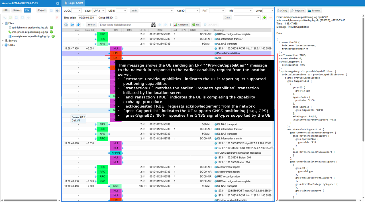
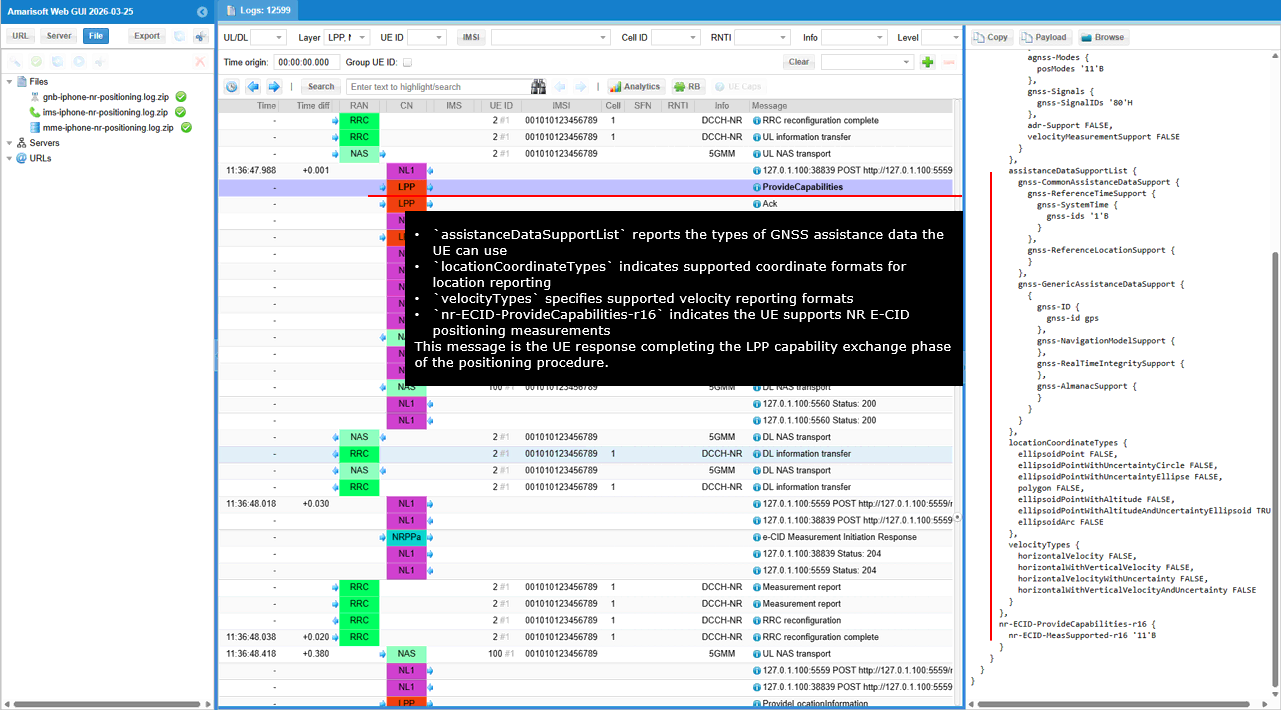
This message shows the LMF sending an LPP Ack message to the UE in response to the UE�s ProvideCapabilities message. The message Ack indicates that the location server successfully received and processed the LPP message sent by the UE.
The parameter ackIndicator set to 0 indicates successful acknowledgement of the previous LPP message. The field ackRequested set to FALSE indicates that no additional acknowledgement is requested from the UE. The field endTransaction set to FALSE indicates that the LPP positioning transaction continues after this acknowledgement.
This message confirms that the LMF successfully received the UE capability information and the LPP positioning signaling exchange continues between the UE and the location server.
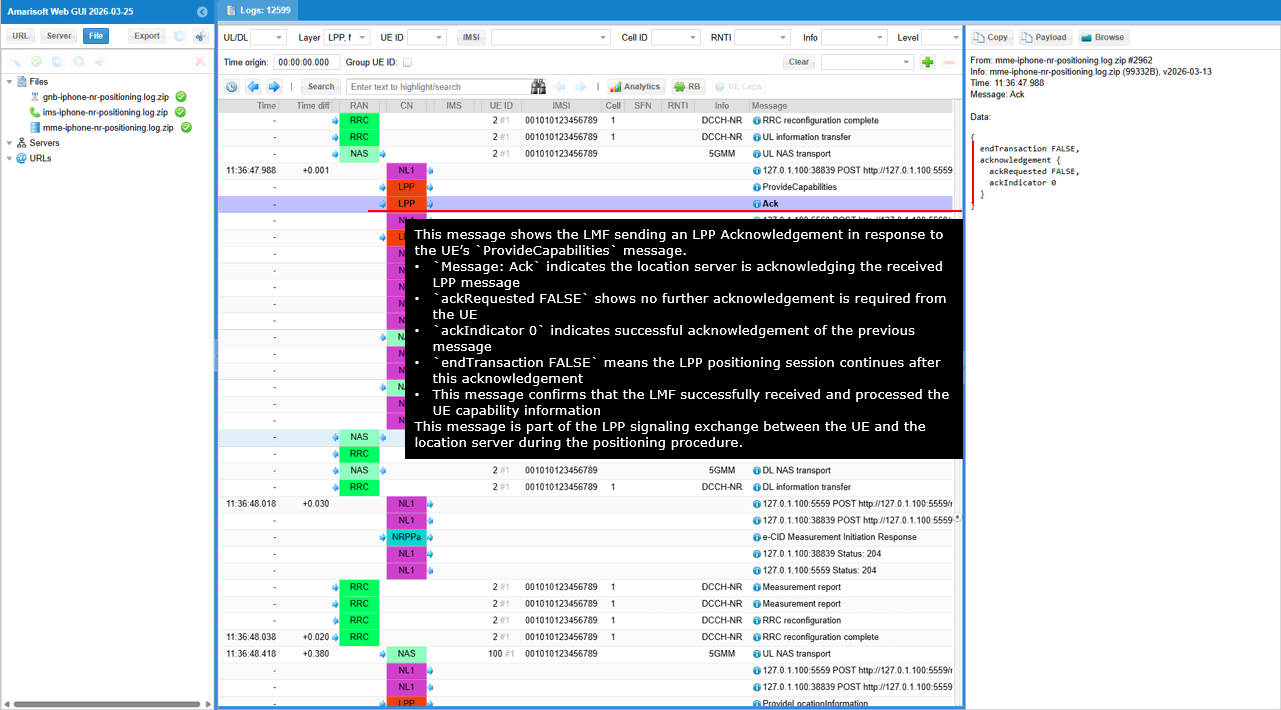
This message shows the LMF sending an LPP message toward the UE through the AMF using the N1/N2 message transfer procedure. The LMF sends an HTTP POST to the AMF API for UE-related N1/N2 message delivery.
The path /namf-comm/v1/ue-contexts/imsi-001010123456789/n1-n2-messages indicates that the request is used to deliver an N1 message toward the UE. The field n1MessageClass set to LPP indicates that the message carried toward the UE is an LPP positioning message.
The field n1MessageContent with contentId set to lpp-pdu identifies the LPP payload included in the multipart body of the HTTP request. The content type application/vnd.3gpp.5gnas indicates that the payload is encoded as 5G NAS content for delivery to the UE.
The field lcsCorrelationId is used to correlate this message with the ongoing positioning procedure. The field n1n2FailureTxfNotifURI provides the callback URI that the AMF should use if the N1/N2 message delivery fails.
The field pei identifies the UE device that is the target of this positioning message. This message is part of the LPP signaling exchange in which the LMF sends positioning messages to the UE through the AMF.
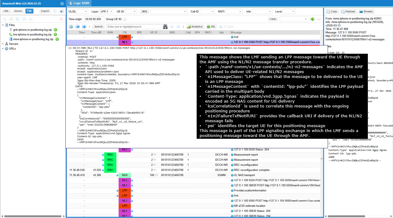
This message shows the LMF sending an LPP RequestLocationInformation message to the UE to start the positioning measurement procedure. The message RequestLocationInformation asks the UE to perform positioning measurements and report the results.
The transactionID identifies the positioning transaction initiated by the location server. The parameter locationInformationType set to locationEstimatePreferred indicates that the location server prefers the UE to compute and return a location estimate.
The locationCoordinatesType field lists the coordinate formats supported for the returned location information, such as ellipsoid point with altitude and uncertainty. The a-gnss-RequestLocationInformation element indicates that the request uses A-GNSS positioning methods. The gnss-PositioningSignals field specifies the GNSS signals to be used for the measurement.
The field nr-ECID-RequestLocationInformation-r16 indicates that NR E-CID measurements are also requested. The parameter endTransaction set to FALSE indicates that the positioning session continues after this request.
This message is part of the LPP positioning procedure in which the location server instructs the UE to collect GNSS or radio measurements and provide location information.
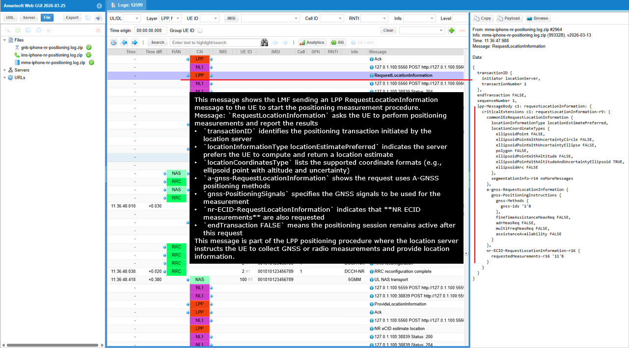
This message shows the LMF sending an LPP message to the UE through the AMF using the N1/N2 message transfer procedure. The HTTP POST request to /namf-comm/v1/ue-contexts/imsi-001010123456789/n1-n2-messages indicates that the AMF API is used to deliver an N1 message toward the UE.
The field n1MessageClass set to LPP indicates that the message being delivered to the UE is an LPP positioning message. The n1MessageContent with contentId lpp-pdu identifies the LPP payload included in the multipart body of the request. The content type application/vnd.3gpp.5gnas indicates that the payload is encoded as a 5G NAS container for UE delivery.
The field lcsCorrelationId is used by the LMF to correlate this message with the ongoing positioning procedure. The field pei identifies the target UE associated with this positioning request. The field n1n2FailureTxfNotifURI provides the callback URI that the AMF should use if the delivery of the N1 or N2 message fails.
This message is part of the positioning procedure in which the LMF sends an LPP positioning command to the UE through the AMF using the N1 message delivery mechanism.
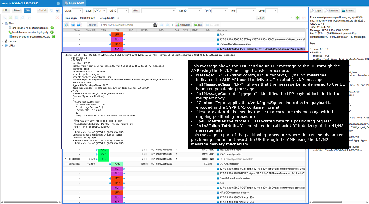
This message shows the AMF forwarding an LPP message toward the UE using the N1/N2 message transfer procedure. The HTTP POST request to /namf-comm/v1/ue-contexts/imsi-001010123456789/n1-n2-messages indicates that the AMF API is being used to deliver an N1 message associated with the UE.
The field n1MessageClass set to LPP indicates that the payload delivered to the UE is an LPP positioning message. The field n1MessageContent with contentId lpp-pdu identifies the binary LPP payload included in the multipart message body. The Content-Type application/vnd.3gpp.5gnas indicates that the payload is carried in the NAS container format used for UE delivery.
The field lcsCorrelationId is used to associate this message with the ongoing positioning session. The field pei identifies the target UE involved in the positioning procedure. The field n1n2FailureTxfNotifURI specifies the callback URI that the AMF should use to report a delivery failure for the N1 or N2 message.
This message is part of the positioning signaling sequence in which the AMF forwards the LPP message toward the UE so that the positioning procedure initiated by the LMF can continue.
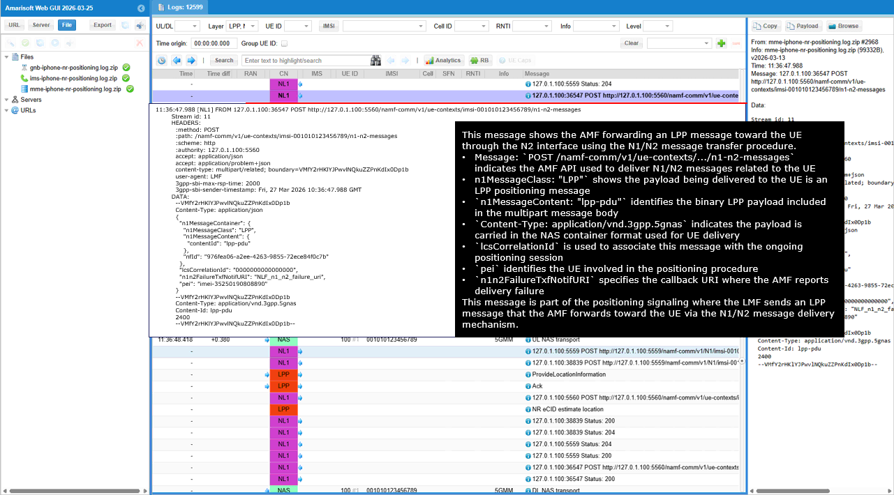
This message shows the AMF sending an LPP positioning message to the UE using NAS signaling over the N1 interface. The LPP payload generated by the LMF is encapsulated inside a NAS Transport message and delivered to the UE through the RAN.
The message DL NAS transport indicates that the core network is sending a NAS message toward the UE. The protocol discriminator value 0x7E identifies the message as a 5G Mobility Management message. The message type 0x68 indicates the NAS message type DL NAS Transport.
The payload container type set to 3 indicates that the payload carried inside the NAS message is an LTE/NR positioning protocol message, which corresponds to LPP. The payload container contains the encoded LPP message that the UE must process as part of the positioning procedure.
The field endTransaction set to FALSE indicates that the positioning transaction remains active and more LPP messages may follow. The field ackRequested set to FALSE indicates that the sender does not require an acknowledgement for this message. The field ackIndicator set to 0 identifies the sequence number associated with the acknowledgement context for the LPP exchange.
This message is part of the positioning signaling sequence in which the AMF forwards the LPP message received from the LMF to the UE through NAS signaling so that the UE can continue the positioning measurements and report the results back through the LPP procedure.
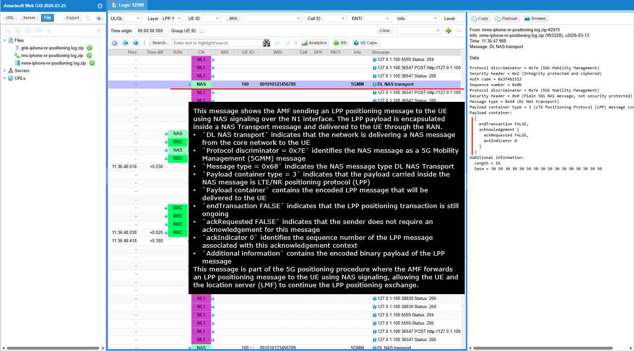
This message shows the AMF delivering an LPP acknowledgement message to the UE using NAS signaling over the N1 interface. The LPP payload is encapsulated inside a NAS DL NAS Transport message and sent toward the UE through the RAN.
The message DL NAS transport indicates that the core network is sending a NAS message to the UE. The protocol discriminator value 0x7E identifies the message as part of the 5G Mobility Management protocol. The message type 0x68 indicates that the NAS message type is DL NAS Transport.
The payload container type set to 3 indicates that the payload carried inside the NAS message corresponds to the LTE/NR positioning protocol, which is LPP. The payload container contains the encoded LPP acknowledgement message associated with the ongoing positioning procedure.
The field endTransaction set to FALSE indicates that the LPP positioning transaction remains active and additional positioning messages may follow. The field ackRequested set to FALSE indicates that no further acknowledgement is required for this message. The field ackIndicator set to 0 identifies the acknowledgement sequence context associated with the LPP message exchange.
This message is part of the LPP positioning procedure in which the network forwards an acknowledgement message to the UE so that the positioning signaling exchange between the UE and the location server can continue.
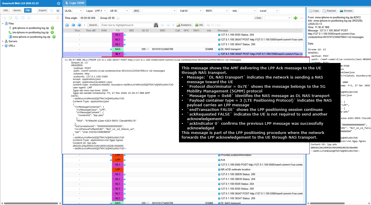
This message shows the AMF delivering an LPP RequestLocationInformation message to the UE using NAS signaling over the N1 interface. The LPP payload generated by the LMF is encapsulated inside a NAS DL NAS Transport message and sent toward the UE through the RAN.
The message DL NAS transport indicates that the network is sending a NAS message toward the UE. The protocol discriminator value 0x7E identifies the message as part of the 5G Mobility Management protocol. The message type 0x68 indicates that the NAS message type is DL NAS Transport.
The payload container type set to 3 indicates that the payload carried inside the NAS message corresponds to the LTE/NR positioning protocol, which is LPP. The payload container contains the encoded RequestLocationInformation message.
The transactionID identifies the positioning transaction initiated by the location server. The requestLocationInformation message instructs the UE to perform positioning measurements and report the results. The a-gnss-RequestLocationInformation indicates that GNSS based positioning measurements are requested. The nr-ECID-RequestLocationInformation indicates that NR ECID radio measurements are also requested.
The field endTransaction set to FALSE indicates that the positioning session remains active and additional positioning messages may follow.
This message is part of the LPP positioning procedure in which the network forwards the location server request to the UE using NAS signaling so that the UE can perform the requested positioning measurements.
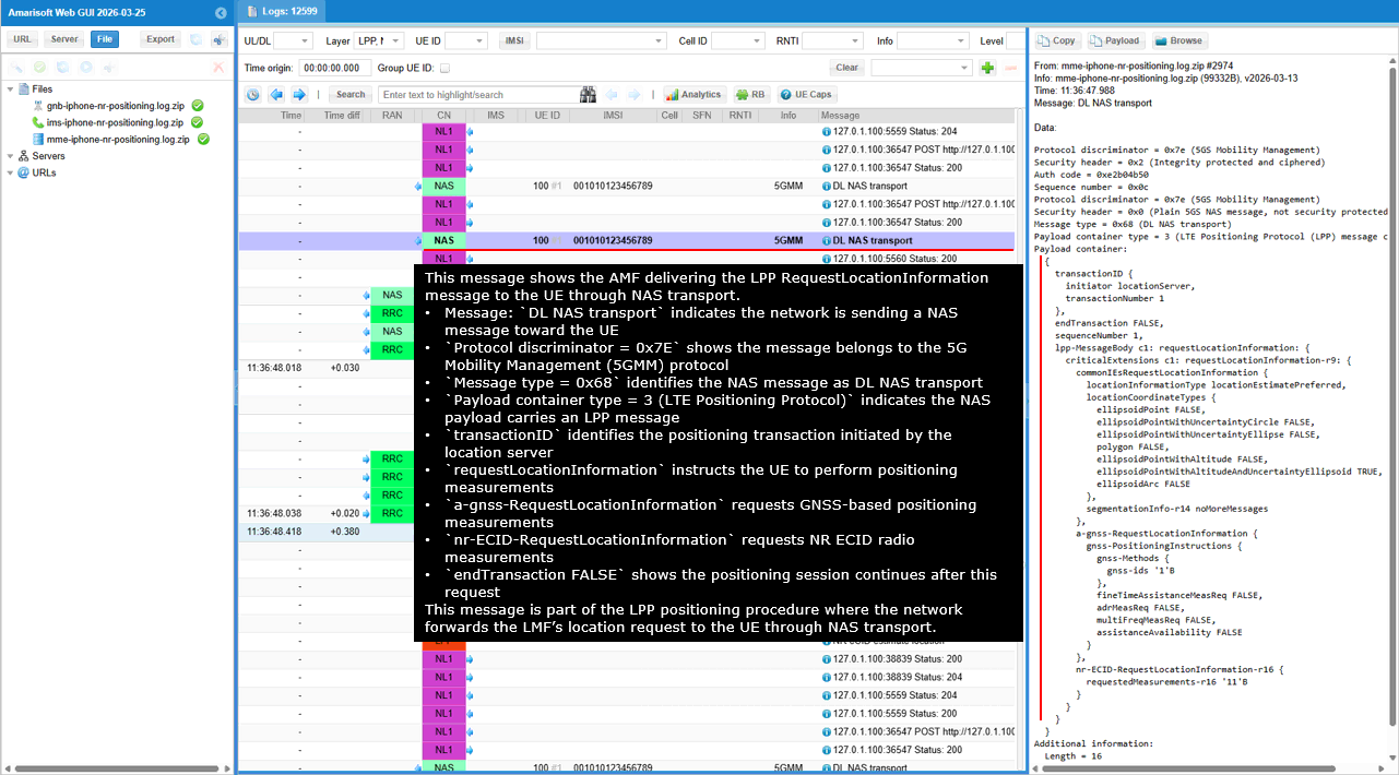
This message shows the AMF sending an N2 notification to the LMF carrying an NRPPa message related to the positioning procedure. The HTTP POST request to /namf-comm/v1/n2/imsi-001010123456789/notify indicates that the AMF is notifying another network function about an N2 message received from the RAN.
The field n2NotifySubscriptionId identifies the subscription that was previously created for receiving N2 message notifications. The field n2InfoContainer contains the N2 message information being reported to the LMF. The field n2InfoClass set to NRPPa indicates that the N2 message belongs to the NR Positioning Protocol A used between the gNB and the LMF.
The field ngapType set to NRPPa_PDU indicates that the payload carried in the notification is an NRPPa protocol data unit. The field contentId notifyN2 identifies the binary NRPPa payload included in the multipart body of the message. The content type application/vnd.3gpp.ngap indicates that the payload contains signaling data received over the NGAP/N2 interface.
This message is part of the positioning signaling exchange where the AMF forwards NRPPa positioning information received from the RAN toward the LMF so that the location server can continue processing the positioning procedure.
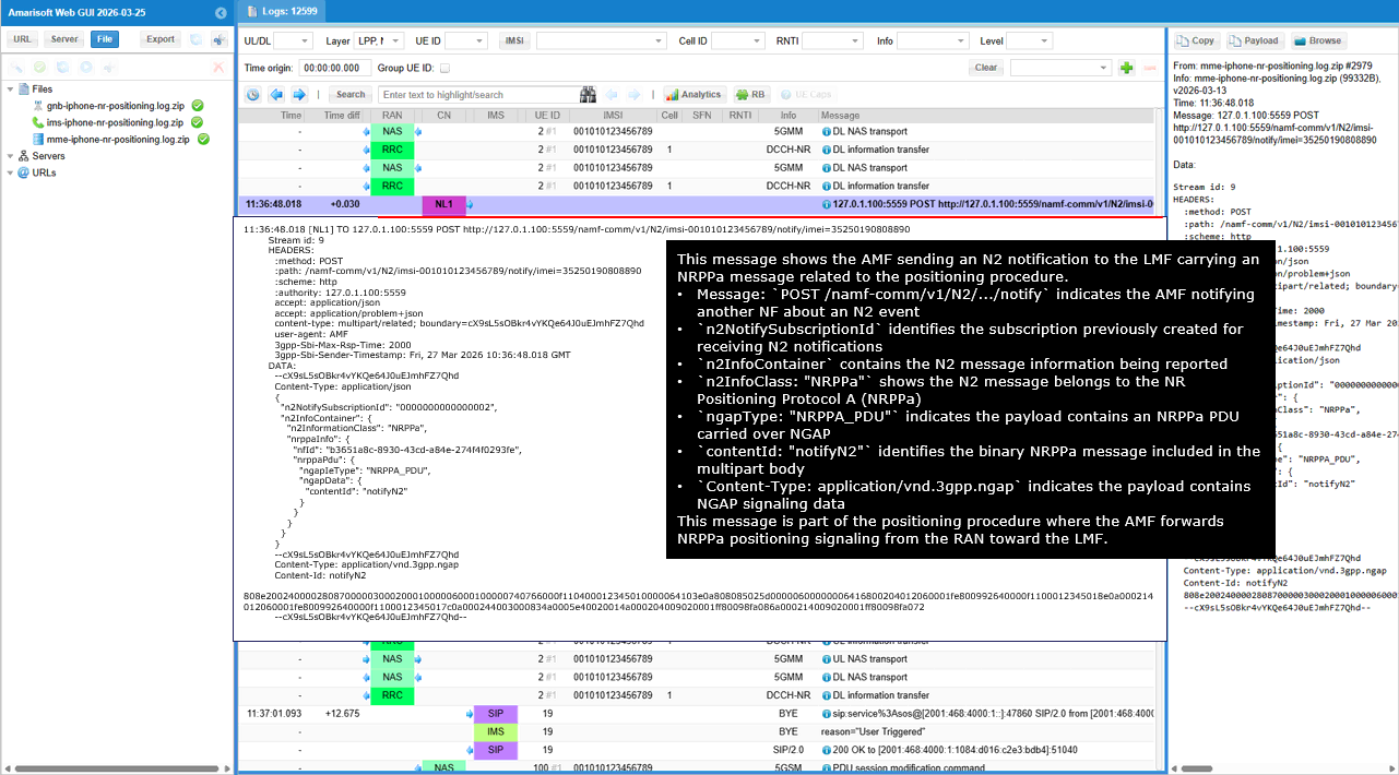
This message shows the AMF notifying the LMF about an N2 positioning message received from the gNB. The HTTP POST request to /namf-comm/v1/n2/imsi-001010123456789/notify indicates that the AMF is sending an N2 notification to a subscribed network function.
The field n2NotifySubscriptionId identifies the subscription that was previously created by the LMF to receive N2 message notifications. The field n2InfoContainer contains the N2 message information that the AMF reports to the LMF. The field n2InfoClass set to NRPPa indicates that the message belongs to the NR Positioning Protocol A used between the gNB and the LMF.
The field ngapType set to NRPPa_PDU indicates that the payload contains an NRPPa protocol data unit. The field contentId notifyN2 identifies the binary NRPPa payload included in the multipart message body. The content type application/vnd.3gpp.ngap indicates that the payload contains signaling received over the NGAP interface on N2.
This message is part of the positioning procedure where the AMF forwards NRPPa positioning signaling received from the RAN toward the LMF so that the location server can continue processing the positioning operation.
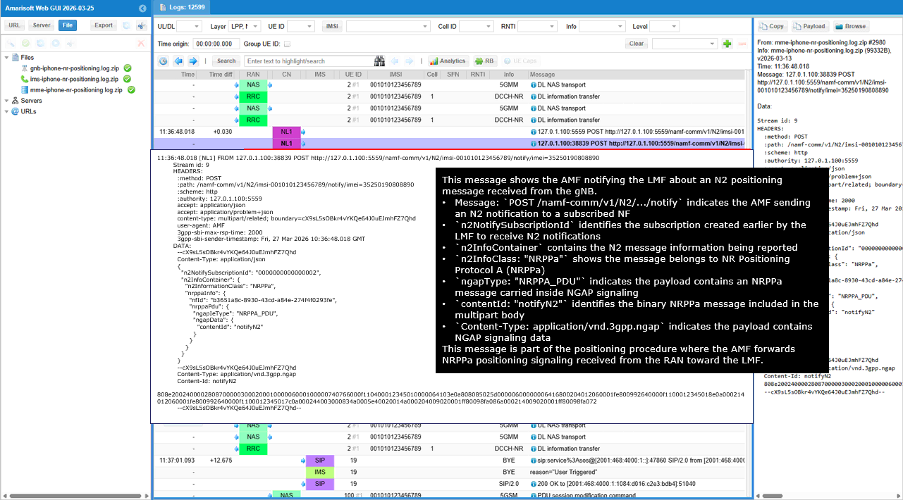
This message shows the gNB sending an NRPPa eCID Measurement Initiation Response to the LMF after executing the positioning measurement request received earlier. The response carries the measurement identifiers, serving cell information, and radio measurement results collected by the gNB that will be used by the LMF to estimate the UE location.
The field successfulOutcome indicates that the eCID measurement procedure completed successfully. The procedureCode eCIDMeasurementInitiation identifies that this response corresponds to the NRPPa eCID measurement initiation procedure previously triggered by the LMF.
The field lMF-UE-Measurement-ID correlates this response with the measurement request issued by the LMF. The field rAN-UE-Measurement-ID is the measurement identifier assigned by the gNB for this measurement session.
The servingCellInfo field identifies the serving NR cell used for the positioning procedure. The PLMN-Identity and NR-CellID specify the identity of the serving cell. The gNB-Position provides the geographical coordinates of the gNB site, including latitude, longitude, altitude, and associated uncertainty parameters that describe the location of the base station used in the positioning calculation.
The measuredResults section contains the radio measurements collected by the gNB. The nr-PCI identifies the physical cell ID of the measured NR cell. The nr-ARFCN specifies the carrier frequency of the measured cell. The RSRP values represent the received signal strength measured for the serving and neighbor cells. The RSRQ values represent the signal quality measurements associated with those cells.
Additional measurement information such as AngleOfArrivalNR provides directional radio information observed at the gNB antenna system. Neighbor cell measurements are also included so that the LMF can apply multilateration or ECID based positioning algorithms using signal strength, signal quality, and radio geometry information collected from the network.
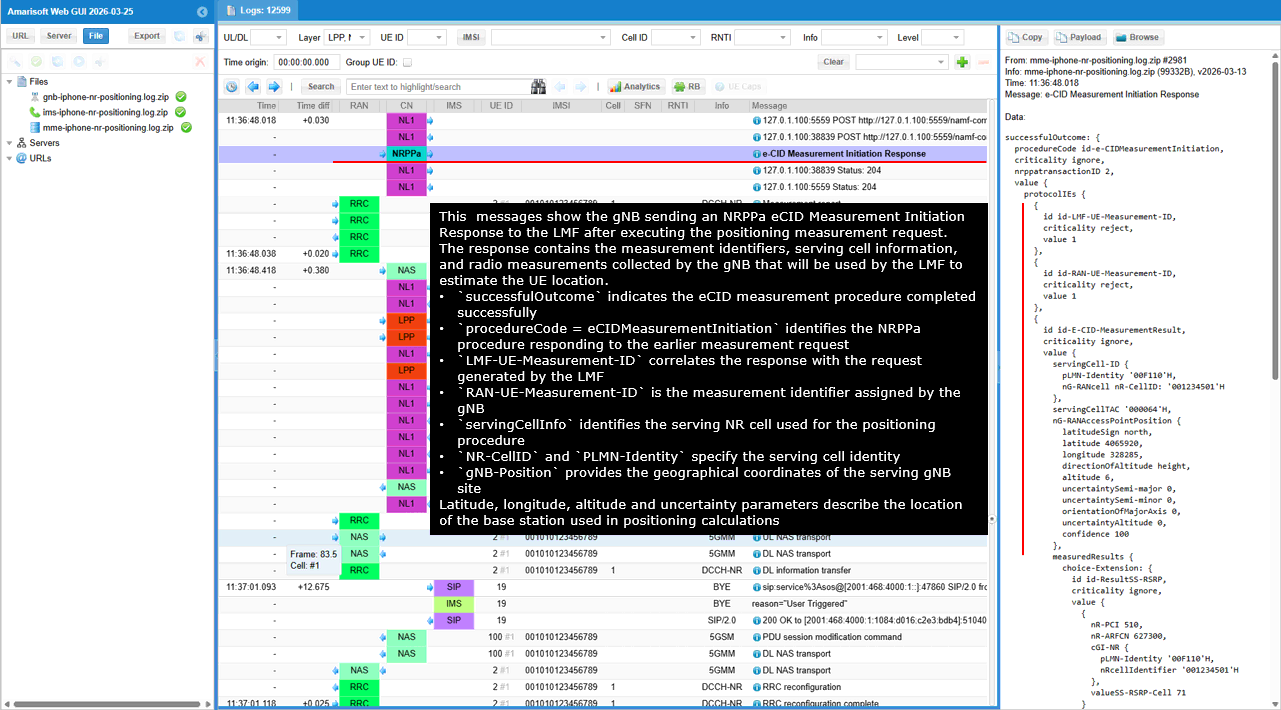
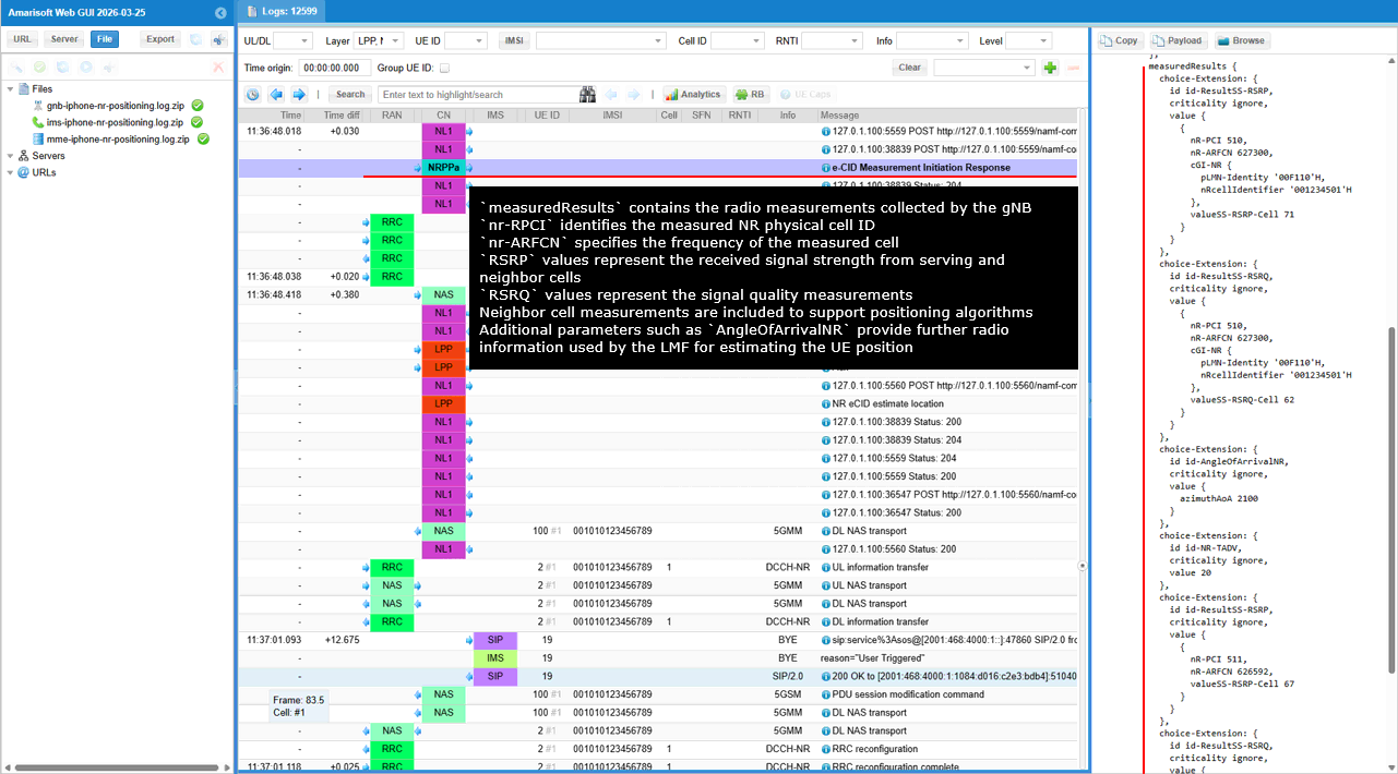
This message shows the UE sending an RRC MeasurementReport to the gNB containing radio measurements of the serving cell and neighbor cells. These measurements are used by the network for procedures such as mobility management and positioning.
The message measurementReport indicates that the UE is reporting radio measurement results according to a measurement configuration previously provided by the network. The field measId identifies the measurement configuration associated with this report.
The field measResultServingCell contains the measurement results for the serving NR cell. The physCellId value 510 identifies the PCI of the serving cell. The RSRP value 71 represents the received signal strength measured from the serving cell. The RSRQ value 62 represents the signal quality measurement for the serving cell.
The field measResultNeighCells contains the measurements for neighbor cells detected by the UE. The physCellId value 511 identifies the PCI of the neighbor cell. The neighbor cell measurement results include RSRP and RSRQ values that describe the received signal strength and signal quality from that cell.
This message is part of the radio measurement reporting procedure where the UE periodically or event-triggeredly reports radio signal measurements to the gNB. The network can use these measurements to support mobility decisions as well as positioning procedures such as ECID.
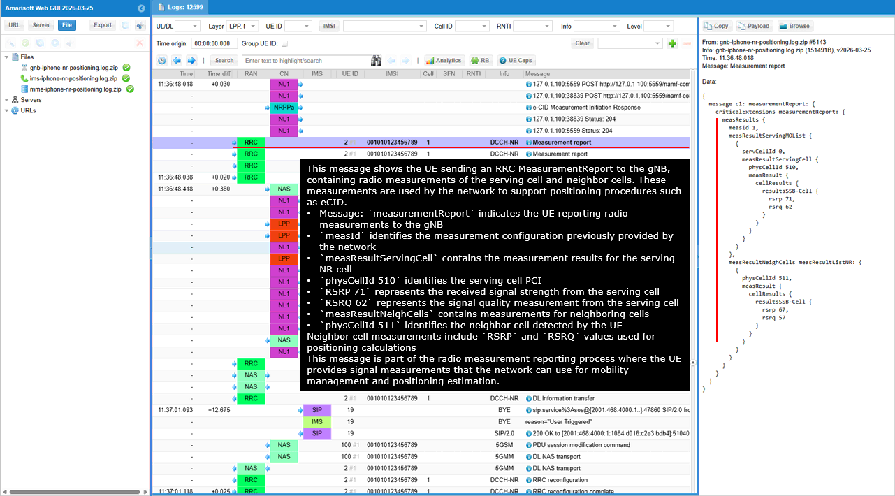
This message shows the UE sending another RRC MeasurementReport to the gNB using a different measurement configuration. The report contains radio measurements of the serving cell and detected neighbor cells that can be used by the network for mobility or positioning analysis.
The message measurementReport indicates that the UE is reporting radio measurement results to the gNB. The field measId 2 identifies the measurement configuration that triggered this report.
The field measResultServingCell contains the measurement results for the serving NR cell. The physCellId value 510 identifies the PCI of the serving cell. The RSRP value 71 represents the received signal strength measured from the serving cell. The RSRQ value 62 represents the signal quality measurement from the serving cell.
The field measResultNeighCells lists measurement results for neighbor cells detected by the UE. The physCellId value 511 identifies the neighboring NR cell detected during the measurement.
This message is part of the UE radio measurement reporting procedure where the UE provides signal measurements to the gNB so that the network can use the information for mobility management or positioning estimation.
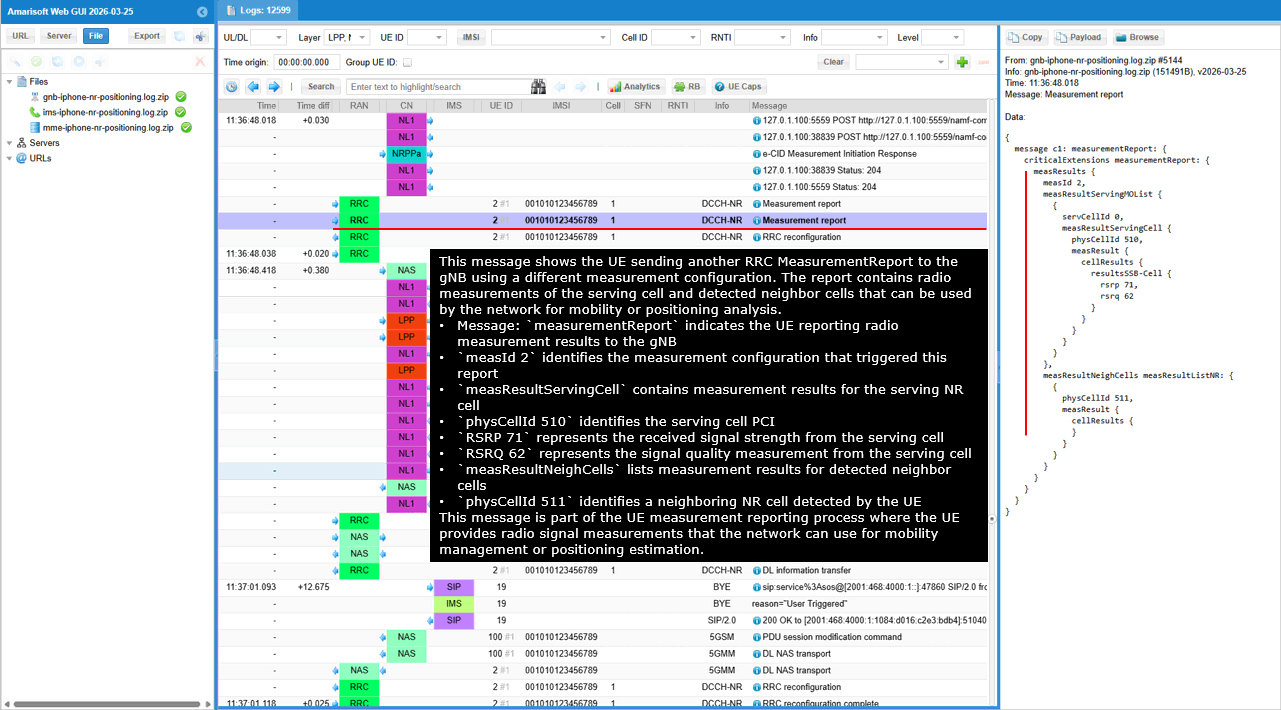
This message shows the UE sending an LPP ProvideLocationInformation message to the network using UL NAS Transport after completing the requested positioning measurements. The LPP payload is carried inside the NAS message and delivered to the core network through the gNB.
The ProvideLocationInformation message contains the UE estimated position together with GNSS timing information and NR radio measurements. The locationEstimate field provides the UE calculated geographic position including latitude, longitude, altitude, and uncertainty parameters.
The gnss-ProvideLocationInformation section includes GNSS reference time information used when calculating the UE position. The nr-ECID-ProvideLocationInformation section contains NR radio measurements such as PCI, ARFCN, RSRP, and RSRQ for the serving cell and detected neighbor cells.
This message is part of the LPP positioning procedure where the UE reports its calculated position and supporting measurement data so that the LMF can determine or refine the UE location.
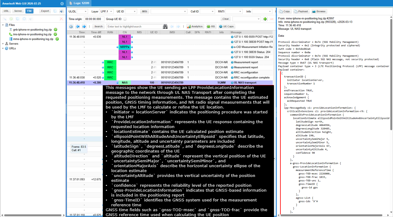
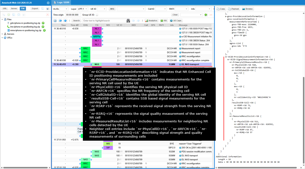
This message shows the AMF forwarding an LPP positioning message received from the UE to the LMF using the Namf Communication interface.
The HTTP POST to /namf-comm/v1/n1n2/.../notify indicates that the AMF is sending an N1 message notification. The field n1MessageClass set to LPP indicates that the forwarded N1 message contains an LPP positioning message. The field n1MessageContent contains the encoded LPP payload received from the UE.
The fields nfId and guami identify the AMF instance and the UE context associated with this message. The fields plmnId, amfId, and nrCellId identify the network and cell where the UE is currently connected. The field imei identifies the device involved in the positioning procedure.
This message is part of the positioning signaling flow where the UE sends an LPP message through NAS, the AMF receives it, and then forwards the positioning information to the LMF so that the location server can process the UE positioning results.
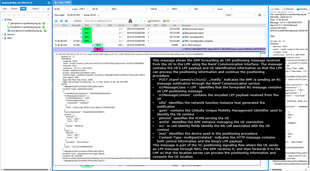
This message is the same Namf N1 message notification as the previous one, but captured on the receiver side. It shows the AMF delivering the LPP message received from the UE to the LMF through the Namf Communication interface. The message carries the UE�s LPP payload and UE identification information so that the LMF can process the positioning result and continue the positioning procedure.
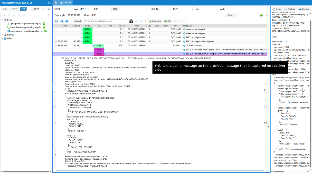
This message shows the UE sending an LPP ProvideLocationInformation message to the location server as part of the positioning procedure. The UE reports its estimated position together with GNSS timing information and NR radio measurements so that the LMF can compute or refine the UE location.
The field ProvideLocationInformation indicates that the UE is returning the positioning information requested earlier by the location server. The initiator set to locationServer indicates that the positioning procedure was initiated by the LMF. The field endTransaction set to TRUE indicates that this message completes the current positioning transaction. The field ackRequested set to TRUE indicates that the UE requests an acknowledgement from the location server.
The locationEstimate field contains the UE calculated geographic position including latitude, longitude, altitude, and uncertainty parameters. The gnss-ProvideLocationInformation section includes GNSS reference time information used in the UE position calculation.
The nr-ECID-ProvideLocationInformation section includes NR radio measurements such as PCI, ARFCN, RSRP, and RSRQ for the serving cell and detected neighbor cells.
This message is part of the LPP positioning procedure where the UE reports its calculated position and measurement information so that the LMF can finalize the UE location estimation.
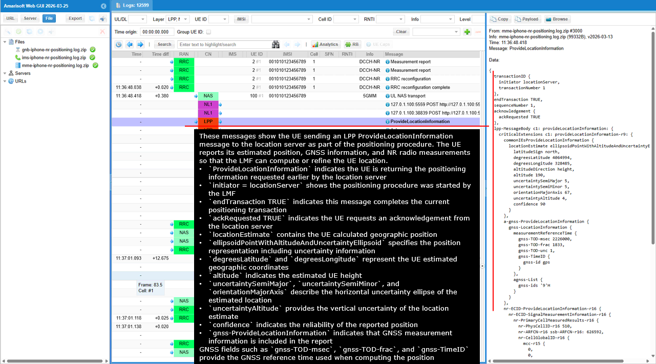
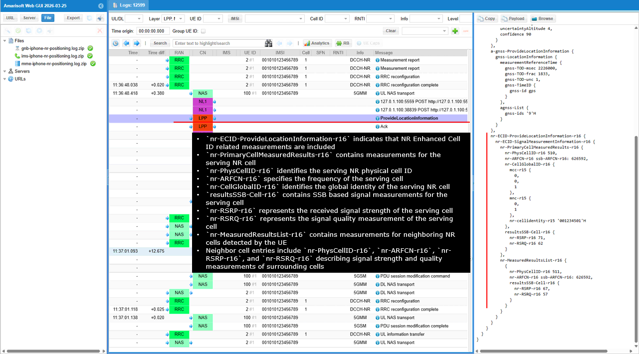
This message shows the receiver confirming successful reception of the previous LPP message by sending an LPP Ack message.
The message Ack indicates that the previous LPP message was received and processed successfully. The field endTransaction set to FALSE indicates that the LPP transaction is still ongoing and additional LPP messages may follow. The field ackRequested set to FALSE indicates that the sender of this Ack message does not require another acknowledgement. The field ackIndicator set to 1 identifies the sequence number of the LPP message being acknowledged.
This message is part of the LPP acknowledgement mechanism used to confirm successful delivery of positioning messages between the UE and the location server.

This message shows the LMF sending an N1N2 message to the AMF using the Namf Communication interface after processing the UE positioning information. The message carries an LPP payload that the AMF will deliver to the UE through NAS signaling.
The HTTP POST to /namf-comm/v1/ue-contexts/.../n1-n2-messages indicates that the LMF is requesting the AMF to deliver an N1 message to the UE. The field n1MessageContainer contains the N1 message that must be forwarded to the UE. The field n1MessageClass set to LPP indicates that the message being sent to the UE is an LPP positioning message. The field n1MessageContent references the payload section containing the encoded LPP message.
The field nfId identifies the network function instance that generated the request. The payload section identified by contentId lpp-pdu contains the binary LPP message that will be delivered to the UE.
This message is part of the positioning procedure where the LMF instructs the AMF to send an LPP message to the UE so that the LPP positioning exchange between the UE and the location server can continue.
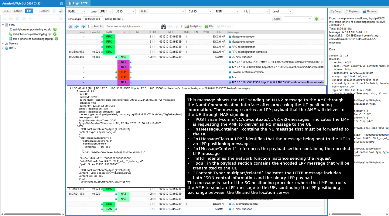
This log shows the NR ECID estimated location produced by the network after processing the UE positioning information. It represents the position calculated by the LMF using the measurements and location data previously reported by the UE.
The entry NR ECID estimate location indicates that this is the calculated positioning result rather than a signaling message. The field Estimated NR-ECID UE pos provides the estimated UE geographic position including latitude, longitude, and altitude. The latitude 43.7217 degrees and longitude 7.2809 degrees indicate the estimated UE location. The altitude 6.0000 meters represents the estimated UE height.
The field Estimated NR-ECID UE coord provides the same position expressed in Cartesian coordinates used internally by the positioning calculation.
This log entry represents the final step of the positioning procedure where the network computes the UE location after processing the LPP measurement reports and radio measurement information.
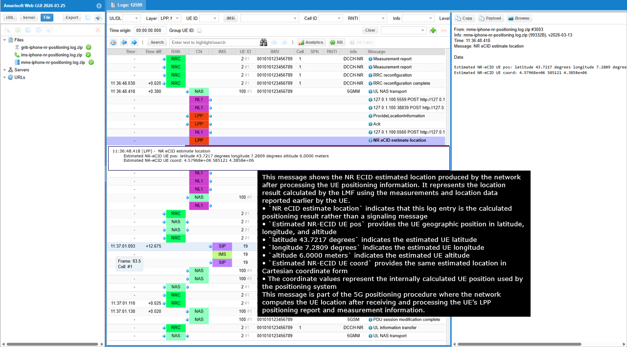
This message shows the HTTP response returned after the positioning server delivers the NR ECID location estimate. The response confirms that the positioning request was successfully processed and returns the estimated UE location.
The status 200 indicates that the HTTP request was successfully handled. The content-type application/json shows that the returned data is encoded in JSON format. The field locationEstimate contains the estimated UE position calculated by the positioning system. The shape value POINT_ALTITUDE indicates that the position is represented as a geographic point with altitude information. The field lon provides the estimated longitude of the UE. The field lat provides the estimated latitude of the UE. The field altitude provides the estimated UE altitude in meters.
This response completes the positioning procedure by returning the calculated UE location after processing the measurement information and LPP positioning exchange.
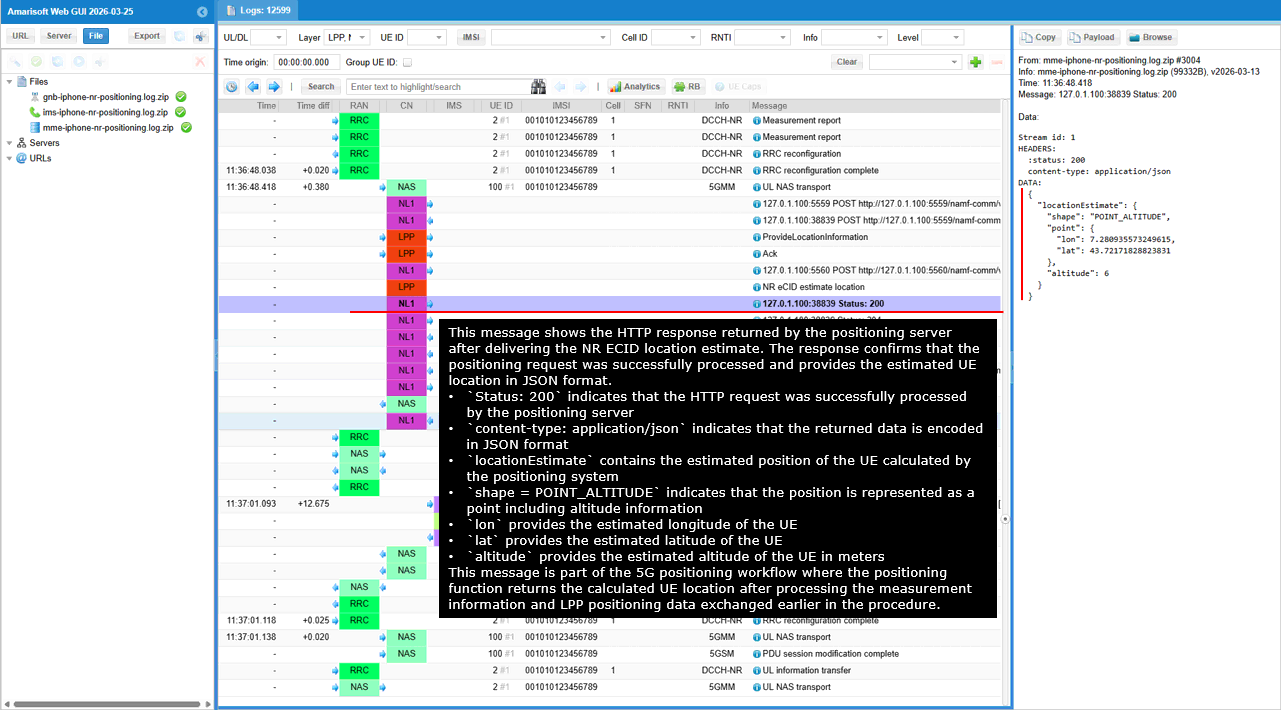
This message shows the LMF sending another N1N2 message request to the AMF through the Namf Communication interface. The request instructs the AMF to deliver an LPP message to the UE through NAS signaling so that the positioning procedure can continue.
The HTTP POST to /namf-comm/v1/ue-contexts/.../n1-n2-messages indicates that the LMF is requesting the AMF to deliver an N1 message to the UE. The field n1MessageContainer contains the N1 message that will be forwarded to the UE. The field n1MessageClass set to LPP indicates that the message being delivered to the UE is an LPP positioning message. The field n1MessageContent references the payload section that contains the encoded LPP message.
The field nfId identifies the network function instance sending the request. The field lcCorrelationId provides the correlation identifier used to associate this request with the ongoing positioning session. The field n1n2FailureTxfNotifURI specifies the callback URI that will be used if delivery of the N1 message fails.
The payload section identified by contentId lpp-pdu contains the binary LPP message that will be delivered to the UE. This message continues the LPP positioning exchange between the UE and the location server through the AMF.
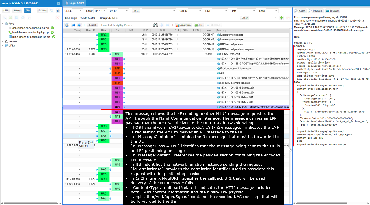
This message shows the HTTP response returned by the AMF after receiving the N1N2 message request from the LMF. The response confirms that the AMF has successfully accepted the request and started the procedure to deliver the N1 message to the UE.
The status 200 indicates that the HTTP request was successfully processed by the AMF. The content-type application/json indicates that the response payload is encoded in JSON format. The field cause with value N1_N2_TRANSFER_INITIATED indicates that the AMF has initiated the procedure to deliver the N1/N2 message toward the UE.
This response corresponds to the earlier POST /namf-comm/v1/ue-contexts/.../n1-n2-messages request sent by the LMF. The message indicates that the AMF acknowledged the request and has begun forwarding the NAS message containing the LPP payload toward the UE.
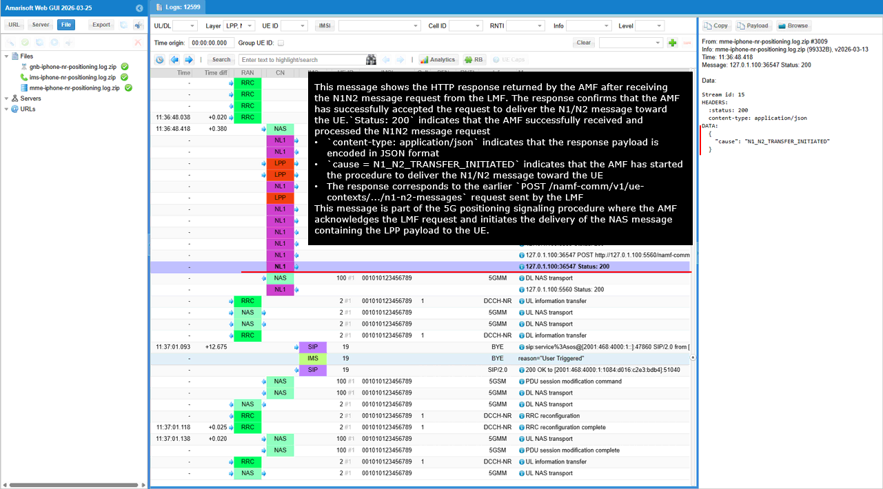
This message shows the AMF delivering an LPP positioning message to the UE using a NAS Downlink NAS Transport message over the N1 interface. The NAS message carries the LPP payload received from the LMF and forwards it to the UE through the RAN.
The message type DL NAS transport indicates that the network is sending a NAS message from the core network to the UE. The payload container type indicates that the transported payload is an LTE Positioning Protocol message. The payload container carries the encoded LPP message that was originally provided by the LMF.
The acknowledgement section shows the context of the LPP transaction. The field endTransaction FALSE indicates that the LPP positioning transaction is still ongoing. The field ackRequested FALSE indicates that the sender does not request an acknowledgement for this message. The field ackIndicator 1 identifies the sequence number associated with the LPP message in the transaction.
This message is part of the 5G positioning procedure where the AMF forwards the LPP positioning message from the LMF to the UE so that the positioning exchange between the UE and the location server can continue.
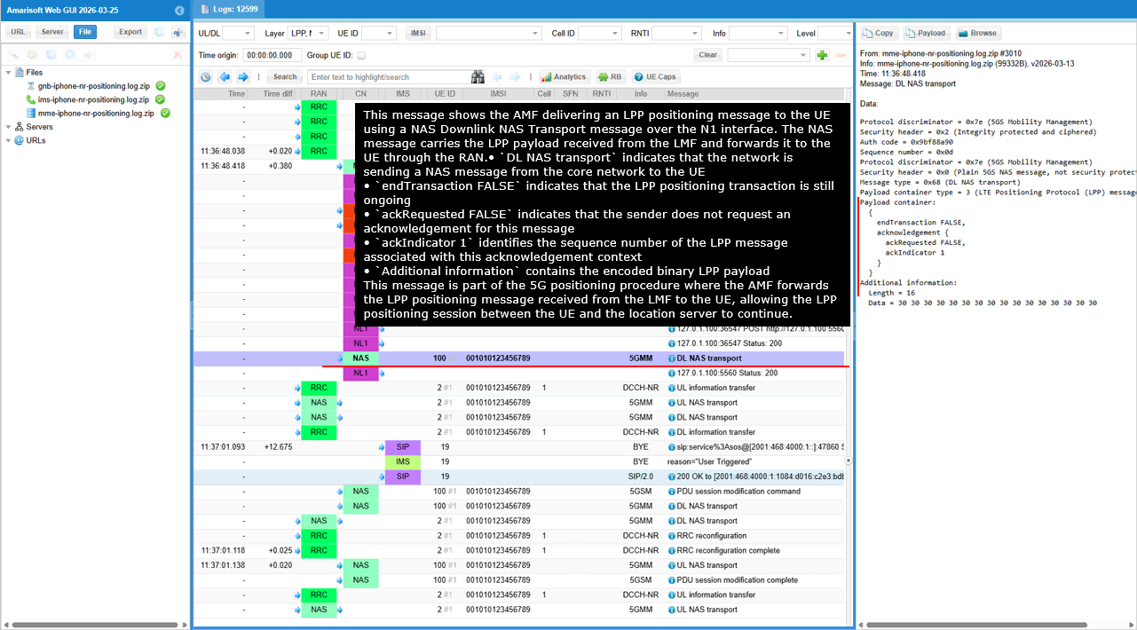
This message shows the HTTP response returned by the AMF after receiving the N1N2 message request from the LMF. The response confirms that the AMF has successfully accepted the request and initiated the delivery of the NAS message toward the UE.
The status 200 indicates that the HTTP request was successfully processed by the AMF. The content-type application/json indicates that the response payload is encoded in JSON format. The field cause with value N1_N2_TRANSFER_INITIATED indicates that the AMF has started the procedure to deliver the N1/N2 message toward the UE.
This response corresponds to the earlier POST /namf-comm/v1/ue-contexts/.../n1-n2-messages request sent by the LMF and confirms that the NAS message containing the LPP payload has been accepted for delivery to the UE.
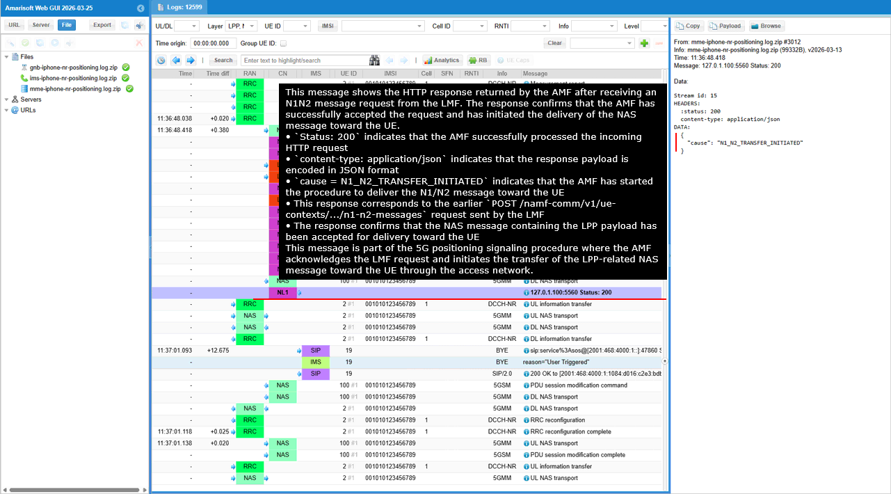
RRC / NAS Signaling
Downlink generic NAS transport /(requestCapability
Message: DL NAS transport
Protocol discriminator = 0x7e (5GS Mobility Management)
Security header = 0x2 (Integrity protected and ciphered)
Auth code = 0xb17aa1e2
Sequence number = 0x05
Protocol discriminator = 0x7e (5GS Mobility Management)
Security header = 0x0 (Plain 5GS NAS message, not security protected)
Message type = 0x68 (DL NAS transport)
Payload container type = 3 (NR Positioning Protocol (LPP) message container)
Payload container:
{
transactionID {
initiator locationServer,
transactionNumber 1
},
endTransaction FALSE,
lpp-MessageBody c1: requestCapabilities: {
criticalExtensions c1: requestCapabilities-r9: {
commonIEsRequestCapabilities {
lpp-message-segmentation-req-r14 '11'B
},
a-gnss-RequestCapabilities {
gnss-SupportListReq TRUE,
assistanceDataSupportListReq TRUE,
locationVelocityTypesReq TRUE
},
otdoa-RequestCapabilities {
},
ecid-RequestCapabilities {
},
nr-ECID-RequestCapabilities-r16 {
},
nr-DL-TDOA-RequestCapabilities-r16 {
}
}
}
}
Additional information:
Length = 16
Data = 30 30 30 30 30 30 30 30 30 30 30 30 30 30 30 30
Uplink generic NAS transport /(provideCapability)
Message: UL NAS transport
Protocol discriminator = 0x7e (5GS Mobility Management)
Security header = 0x2 (Integrity protected and ciphered)
Auth code = 0x40293af6
Sequence number = 0x04
Protocol discriminator = 0x7e (5GS Mobility Management)
Security header = 0x0 (Plain 5GS NAS message, not security protected)
Message type = 0x67 (UL NAS transport)
Payload container type = 3 (NR Positioning Protocol (LPP) message container)
Payload container:
{
transactionID {
initiator locationServer,
transactionNumber 1
},
endTransaction TRUE,
sequenceNumber 0,
acknowledgement {
ackRequested TRUE
},
lpp-MessageBody c1: provideCapabilities: {
criticalExtensions c1: provideCapabilities-r9: {
commonIEsProvideCapabilities {
segmentationInfo-r14 noMoreMessages,
lpp-message-segmentation-r14 '10'B
},
a-gnss-ProvideCapabilities {
gnss-SupportList {
{
gnss-ID {
gnss-id gps
},
agnss-Modes {
posModes '100'B
},
gnss-Signals {
gnss-SignalIDs 'FF'H
},
adr-Support FALSE,
velocityMeasurementSupport FALSE
}
},
locationCoordinateTypes {
ellipsoidPoint TRUE,
ellipsoidPointWithUncertaintyCircle FALSE,
ellipsoidPointWithUncertaintyEllipse FALSE,
polygon FALSE,
ellipsoidPointWithAltitude TRUE,
ellipsoidPointWithAltitudeAndUncertaintyEllipsoid FALSE,
ellipsoidArc FALSE
}
},
nr-ECID-ProvideCapabilities-r16 {
nr-ECID-MeasSupported-r16 '3'H,
periodicalReporting-r16 supported,
triggeredReporting-r16 supported
},
nr-DL-TDOA-ProvideCapabilities-r16 {
nr-DL-TDOA-Mode-r16 {
posModes '001'B
},
nr-DL-TDOA-PRS-Capability-r16 {
maxNrOfDL-PRS-ResourceSetPerTrpPerFrequencyLayer-r16 1,
maxNrOfTRP-AcrossFreqs-r16 n4,
maxNrOfPosLayer-r16 1,
dl-PRS-ResourcesCapabilityBandList-r16 {
{
freqBandIndicatorNR-r16 78,
maxNrOfDL-PRS-ResourcesPerResourceSet-r16 n1,
maxNrOfDL-PRS-ResourcesPerPositioningFrequencylayer-r16 n6
}
},
dl-PRS-ResourcesBandCombinationList-r16 {
{
bandList-r16 {
78
},
maxNrOfDL-PRS-ResourcesAcrossAllFL-TRP-ResourceSet-r16 fr1-Only-r16: n6
}
}
},
nr-DL-TDOA-MeasurementCapability-r16 {
dl-RSTD-MeasurementPerPairOfTRP-FR1-r16 1,
dl-RSTD-MeasurementPerPairOfTRP-FR2-r16 1,
supportOfDL-PRS-RSRP-MeasFR1-r16 supported,
supportOfDL-PRS-RSRP-MeasFR2-r16 supported
},
nr-DL-PRS-QCL-ProcessingCapability-r16 {
dl-PRS-QCL-ProcessingCapabilityBandList-r16 {
{
freqBandIndicatorNR-r16 78
}
}
},
nr-DL-PRS-ProcessingCapability-r16 {
prs-ProcessingCapabilityBandList-r16 {
{
freqBandIndicatorNR-r16 78,
supportedBandwidthPRS-r16 fr1: mhz100,
dl-PRS-BufferType-r16 type1,
durationOfPRS-Processing-r16 {
durationOfPRS-ProcessingSymbols-r16 n1,
durationOfPRS-ProcessingSymbolsInEveryTms-r16 n8
},
maxNumOfDL-PRS-ResProcessedPerSlot-r16 {
}
}
},
maxSupportedFreqLayers-r16 1
},
periodicalReporting-r16 {
posModes '001'B
}
}
}
}
}
Additional information:
Length = 16
Data = 30 30 30 30 30 30 30 30 30 30 30 30 30 30 30 30
Downlink generic NAS transport /(requesting LocationInformation-ecid)
Message: DL NAS transport
Protocol discriminator = 0x7e (5GS Mobility Management)
Security header = 0x2 (Integrity protected and ciphered)
Auth code = 0xe4f31a0b
Sequence number = 0x08
Protocol discriminator = 0x7e (5GS Mobility Management)
Security header = 0x0 (Plain 5GS NAS message, not security protected)
Message type = 0x68 (DL NAS transport)
Payload container type = 3 (LTE Positioning Protocol (LPP) message container)
Payload container:
{
transactionID {
initiator locationServer,
transactionNumber 1
},
endTransaction FALSE,
lpp-MessageBody c1: requestLocationInformation: {
criticalExtensions c1: requestLocationInformation-r9: {
commonIEsRequestLocationInformation {
locationInformationType locationMeasurementsRequired,
qos {
verticalCoordinateRequest FALSE,
responseTime {
time 3,
responseTimeEarlyFix-r12 1
},
velocityRequest FALSE
},
segmentationInfo-r14 noMoreMessages
},
ecid-RequestLocationInformation {
requestedMeasurements '111'B
}
}
}
}
Additional information:
Length = 16
Data = 30 30 30 30 30 30 30 30 30 30 30 30 30 30 30 30
Uplink generic NAS transport /(providing LocationInformation-ecid)
Message: UL NAS transport
Protocol discriminator = 0x7e (5GS Mobility Management)
Security header = 0x2 (Integrity protected and ciphered)
Auth code = 0x5aad91e9
Sequence number = 0x06
Protocol discriminator = 0x7e (5GS Mobility Management)
Security header = 0x0 (Plain 5GS NAS message, not security protected)
Message type = 0x67 (UL NAS transport)
Payload container type = 3 (LTE Positioning Protocol (LPP) message container)
Payload container:
{
transactionID {
initiator locationServer,
transactionNumber 1
},
endTransaction TRUE,
sequenceNumber 0,
acknowledgement {
ackRequested TRUE
},
lpp-MessageBody c1: provideLocationInformation: {
criticalExtensions c1: provideLocationInformation-r9: {
ecid-ProvideLocationInformation {
ecid-SignalMeasurementInformation {
measuredResultsList {
{
physCellId 0,
arfcnEUTRA 0
}
}
}
}
}
}
}
Additional information:
Length = 16
Data = 30 30 30 30 30 30 30 30 30 30 30 30 30 30 30 30