NR DSS
This tutorial is about how to configure for DSS (Dynamic Spectrum Sharing) and verify it works. DSS is a mechanism by which LTE and NR share a same spectrum dynamically. Theoretically there are many different options of impementing DSS as summarized in a diagrame below. In reality, it seems that Option 2 and Option 3 are most common choice of the implementation.
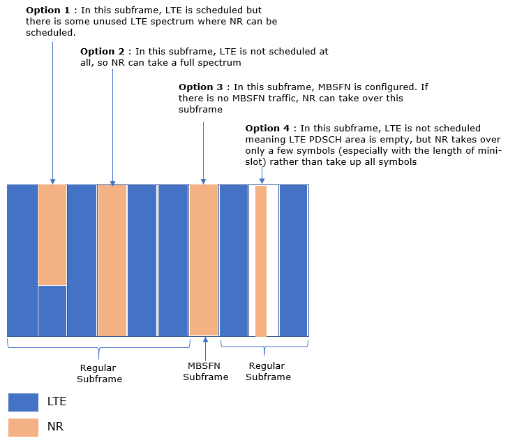
Image Source : Sharetechnote
Even though Option 2 and 3 would be simpler to implement comparing to other options, there are still several factors to be considered / planned carefully to guarantee the co-operation of both LTE and NR in the same spectrum. Followings are some of these factors.
- Shifting NR CORESET
- Rate Matching around LTE CRS
- Rate Maching Around LTE PSS,SSS,PBCH
- Scheduling Symbols not cliding with any of LTE Reference Signal
Table of Contents
Introduction
Dynamic Spectrum Sharing (DSS) is a pivotal technology that enables the simultaneous deployment of LTE (Long-Term Evolution) and NR (New Radio, 5G) within the same frequency spectrum, thereby maximizing spectral efficiency and facilitating smooth network evolution. By leveraging DSS, mobile network operators can dynamically allocate spectrum resources between LTE and 5G NR users based on real-time traffic demand, device capability, and network configuration. This mechanism is especially significant in the early stages of 5G rollout, where spectrum resources are often limited and network operators must support a diverse mix of legacy and next-generation devices. Architecturally, DSS involves intricate coordination at the radio access network (RAN) level, including dynamic scheduling, control channel alignment, and interference mitigation to ensure optimal coexistence and performance for both technologies. The most widely adopted DSS implementations are based on non-MBSFN (Multicast-Broadcast Single Frequency Network) and MBSFN configurations, which allow flexible multiplexing of LTE and NR signals in time and frequency domains. The adoption of DSS accelerates 5G deployment, reduces the need for exclusive spectrum re-farming, and ensures a seamless user experience as networks transition from LTE to 5G NR. Understanding DSS, its configuration, and verification processes is crucial for network engineers, system integrators, and anyone involved in contemporary cellular network deployment and optimization.
-
Context of Dynamic Spectrum Sharing (DSS)
- DSS enables LTE and 5G NR to dynamically share the same spectrum resources, improving network flexibility and spectral efficiency.
- It is a key enabler for operators to expedite 5G rollout without waiting for dedicated spectrum allocations.
- The technology is particularly relevant in scenarios where spectrum bands are scarce or where legacy devices must continue to be supported.
-
Relevance and Importance of the Tutorial
- This tutorial provides detailed guidance on configuring DSS and verifying its operational effectiveness in a test environment.
- It addresses real-world deployment challenges, including coexistence factors such as NR CORESET shifting, LTE reference signal protection, and scheduling alignment.
- Understanding the practical aspects of DSS implementation is essential for ensuring robust network performance and seamless transition between LTE and 5G NR services.
-
Learning Outcomes
- Comprehend the underlying principles and architecture of DSS, including the most common deployment options.
- Acquire hands-on skills to configure DSS using industry-standard tools and configurations (e.g., Amarisoft callbox with gnb-dss.cfg).
- Identify and address key technical factors necessary for successful DSS operation, such as rate matching, reference signal protection, and scheduling considerations.
- Develop proficiency in verifying DSS functionality and troubleshooting common interoperability issues between LTE and NR.
-
Prerequisite Knowledge
- Familiarity with LTE and NR radio access network architecture and basic protocol operations.
- Understanding of spectrum management concepts and cellular network deployment strategies.
- Experience with network test equipment (such as Amarisoft callbox) and configuration file management.
- Basic skills in analyzing radio signal scheduling and interference scenarios.
Summary of the Tutorial
This tutorial demonstrates the test procedures for configuring, executing, and analyzing a Dynamic Spectrum Sharing (DSS) test using Amarisoft systems, with a focus on low-layer LTE and NR coexistence. The following is a structured summary of the methodology and key steps involved:
-
Test Setup:
- Utilize a single SDR card to simultaneously operate both LTE and NR cells, exploiting the DSS feature where both technologies share the same center frequency and bandwidth.
- Use the default SIM card provided by the system.
- No complicated IP layer setup is required; focus remains on the lower layers.
-
Key Configuration Parameters:
- Configure critical parameters such as ul_frequency_shift_7p5_khz, lte_crs, en_dc_scg_cell_list, dmrs_type_a_pos, and pdsch related settings.
- Set MBMS subframes and related allocation parameters for resource sharing and collision avoidance.
- Align channel bandwidth and subcarrier spacing between LTE and NR (e.g., 10 MHz, 15 kHz SCS).
-
Configuration Procedures:
- Edit and use configuration files for gNB/eNB (gnb-dss.cfg) and UEsim (ue-nr-dss.cfg), ensuring:
- ALLOW_SA is set to 1, enabling both LTE and NR initial attach.
- Both LTE and NR cells use the same RF port and spectrum.
- NR SSB is mapped into the MBSFN subframe to reduce collision.
- Measurement reporting is enabled to detect the NR cell before addition.
- DMRS Type-A position is set for NR PDSCH to avoid LTE control region overlap.
- NR PRACH subframe aligns with LTE PRACH subframe.
- NR PDSCH start symbol is set to OFDM symbol 2 or later, and x_overhead is configured to accommodate LTE CRS.
- For UEsim, configure two separate RF ports for LTE and NR connections due to its limitation.
-
Test Execution Steps:
- Verify the cell configuration, ensuring LTE and NR operate with the same bandwidth.
- Check RF information to confirm both cells are running on the same SDR card and spectrum.
- Power on the UE and perform attach procedures.
- Using command-line tools (e.g., t command), confirm both LTE and NR cells are connected on the UE.
- Generate high-rate IP data to visually confirm resource allocation between LTE and NR in the WebGUI.
-
Log Analysis:
- Verify UE capability for DSS support.
- Check MBSFN configuration in LTE SIB messages.
- Ensure NR monitoring symbols and PDSCH allocation do not overlap LTE control channel regions.
- Confirm NR SIB1 settings for frequencyShift7p5khz and PRACH configuration match configuration files.
- After LTE attach, verify UE receives measurement report for NR, enabling NR cell addition.
- Monitor physical traffic channels (PDCCH, PHICH, PUCCH, PDSCH, PUSCH) for both LTE and NR to ensure correct operation.
- Use RB map analysis for visualizing physical channel operation over time.
-
Spectrum Analysis:
- Use Amarisoft’s built-in spectrum analyzer or any suitable spectrum analyzer supporting spectrograms.
- Interpret spectrograms in conjunction with knowledge of signal structure (as color coding is power-based).
- Observe full spectrum utilization and time-domain scheduling for both LTE and NR.
This step-by-step procedure ensures proper DSS configuration, execution, and verification of concurrent LTE and NR operation on shared spectrum. The emphasis is on configuration alignment, collision avoidance, and practical validation using logs and spectrum analysis tools, with all critical steps and test methodologies preserved as described in the tutorial.
Test Setup
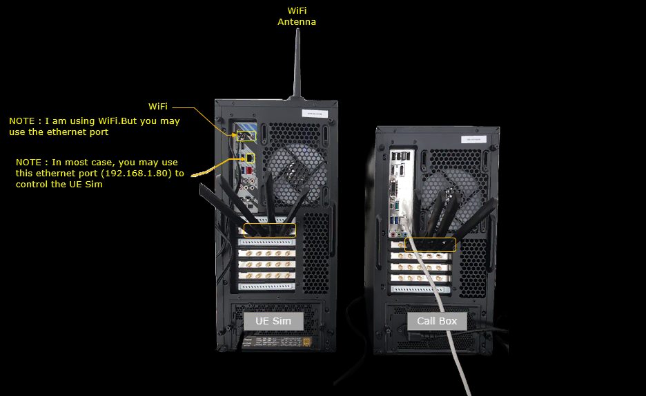
Test setup for this tutorial is as shown below. This is just for low layer testing, you may not need any complicated IP layer setup.
- SIM Card used in this tutorial is the one delivered with the system as it is.
- If you want to change the configuration, The tutorial Configuration Guide would help
Key Configuration Parameters
Followings are important configuration parameters for this tutorial. You may click on the items for the descriptions from Amarisoft documents.
- ul_frequency_shift_7p5_khz
- lte_crs
- en_dc_scg_cell_list
- reserved_mbms_subframes : In this link, you will get the descriptions for all the items listed below
- sf_alloc
- radio_frame_allocation_period
- radio_frame_allocation_offset
- subframe_allocation
- n_symb_cch
- dmrs_type_a_pos
- pdsch
- start_symb
- x_overhead
Configuration
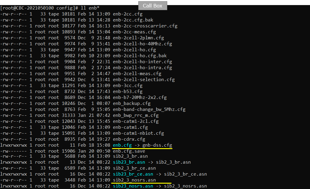
I have used gnb-dss.cfg with minor change and sib2_3_nosrs.asn without any changes.
I am using the default mme, ims config as shown below.

I used ue-nr-dss.cfg which is copied and modifed from ue-nr-nsa.cfg on UEsim.

Following is the configuration in gnb-dss.cfg. In this configuration, I used SISO for simplicity and set ALLOW_SA 1 since we need to allow initial attach for both LTE and NR.

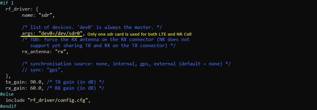
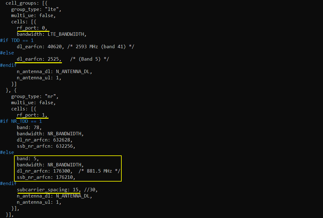
One important thing to notice in rf_driver configuration is that only one sdr card is enabled even when the two difference cell (a LTE cell and a NR cell) will be used in this test. It is because the two cell uses the exactly same rf spectrum (center frequency and bandwidth) and the scheduling in time and frequency domain over the two cell do not collide against each other.
In this test, rf_ports for LTE is not configured.

![]()
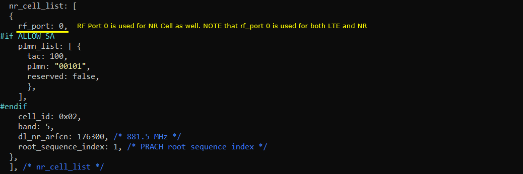
Another important thing to note is that the rf_port of LTE cell (i.e, rf_port in cell_list) and the rf_port of NR cell (i.e, rf_port in nr_cell_list) are same meaning that the two cells are utilizing the same spectrum. This is understandable because the fundamental concept of DSS is to let LTE and NR cell use(share) the same spectrum.

Following is configuration for nr cell. What you need to pay attention is that rf_port in NR cell is same as the rf_port in LTE, which implies that LTE and NR shares the same RF chain.
In this test, I set the LTE channel BW to 10 Mhz by setting n_rb_dl to 50. (

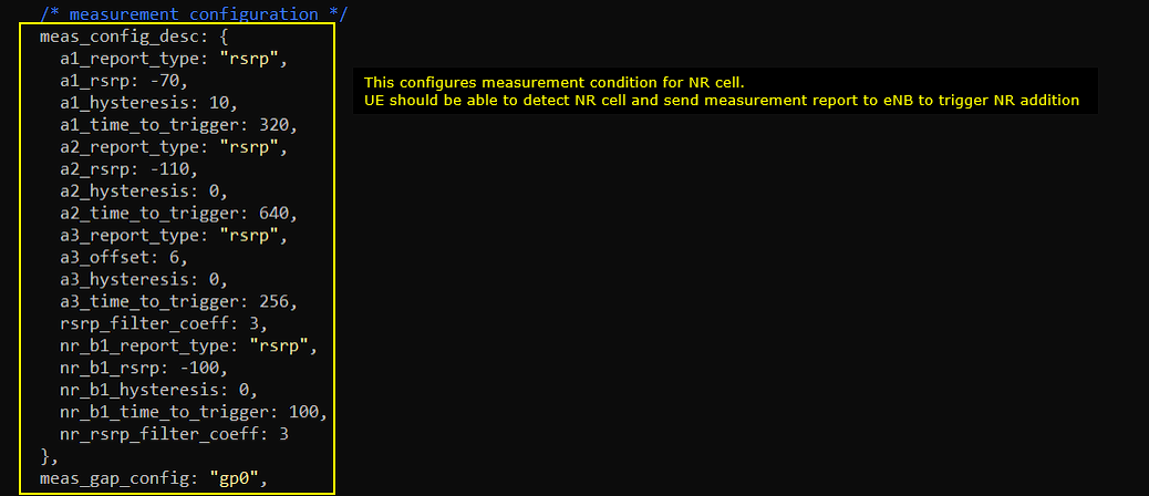
In this test, I configured and enabled measurement report to check the detection of NR cell betore the attempt to add NR cell.
This is important configuration since NR SSB is supposed to be transmitted in this MBSFN slot.

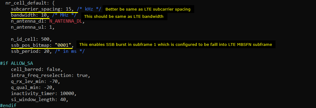
Following is the default configuration of NR cell (nr_cell_default). I set the subcarrier_spacing of NR cell to be same as LTE subcarrier spacing for easy test. Also you should notice that I set the bandwidth to 10Mhz which is the same bandwidth I set for the LTE cell. Another thing to notice is that I set the ssb_pos_bitmap so that the SSB falls into MBSFN subframe.
Another import thing to notice is to set dmrs_type_a_pos (the first OFDM symbole of type A dmrs symbol) to be symbol 3. This is to allow mapping type A PDSCH to start from the third symbol and this is to avoid to allocate NR PDSCH overlapping with any possible control channel region of LTE. I also enabled ul_frequency_shift_7p5_khz to align NR UL/DL shift with LTE UL/DL shift.

Configure NR PRACH subframe to be in the same subframe as LTE PRACH subframe.

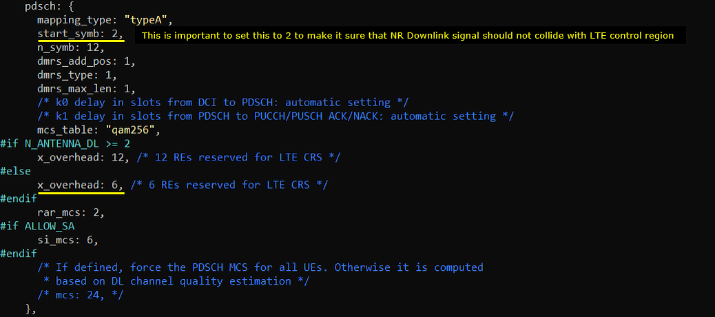
It is important to set the start symbole of NR PDSCH to be OFDM symbol 2 (or greather than symbol 2 is OK) to avoid possible collistion between LTE control channel and NR PDSCH. It is also important to configure the proper x_overhead to give enough rooms for LTE CRS to be allocated in NR PDSCH regions.
No specific configuration is required for NR PUSCH. You can use the default settings for PUSCH.
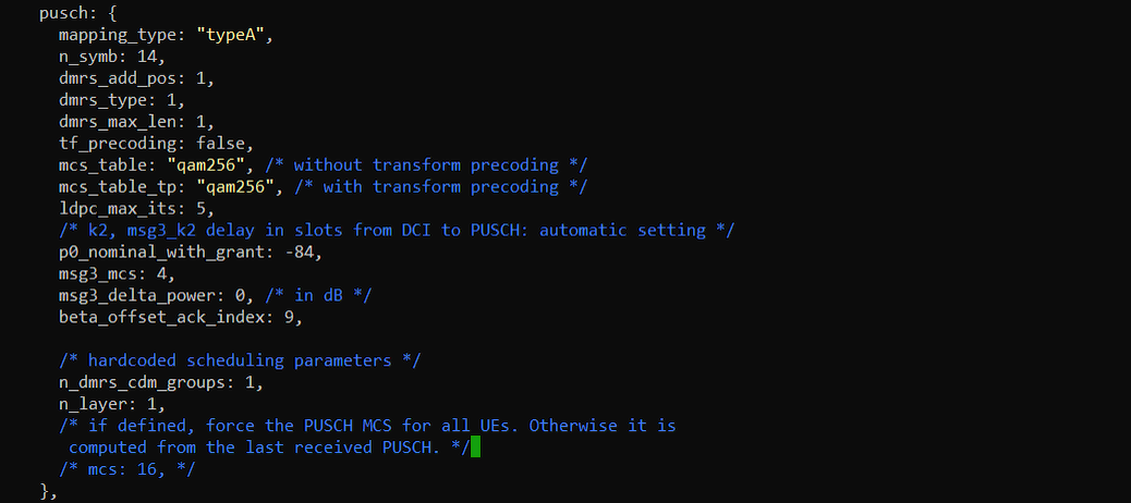
Following is the configuration in ue-nr-dss.cfg in UEsim. (
Configure the UEsim channel bandwidth for both NR and LTE to be same as the NR/LTE bandwidth of gNB/eNB.

UEsim does not allow to share the same rf port, so you need to configure two different rf_port between lte connection and NR connection.
Perform the Test
Check the cell configuration and see if it is configured as intended. Make it sure that same bandwidth are configured for both LTE and NR.

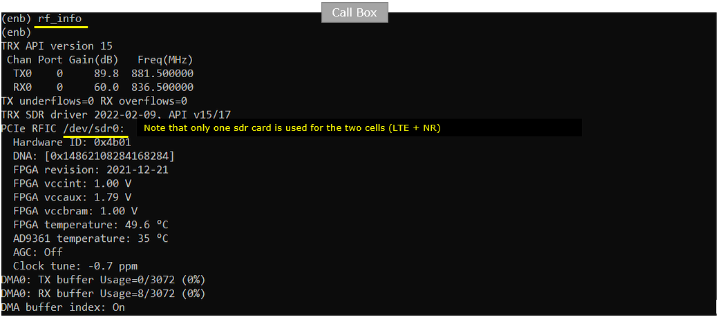
Check RF information with rf_info command. As you see here, only one sdr card is used for the two cells. The frequency shown here are the center frequency of both LTE cell and NR cell.
Power on UE and get it attached.

With t command, confirm that both LTE and NR cell are connected.

Generate the high rate of IP data so that you can easily verify the resource allocation between LTE and NR in WebGUI

Log Analysis
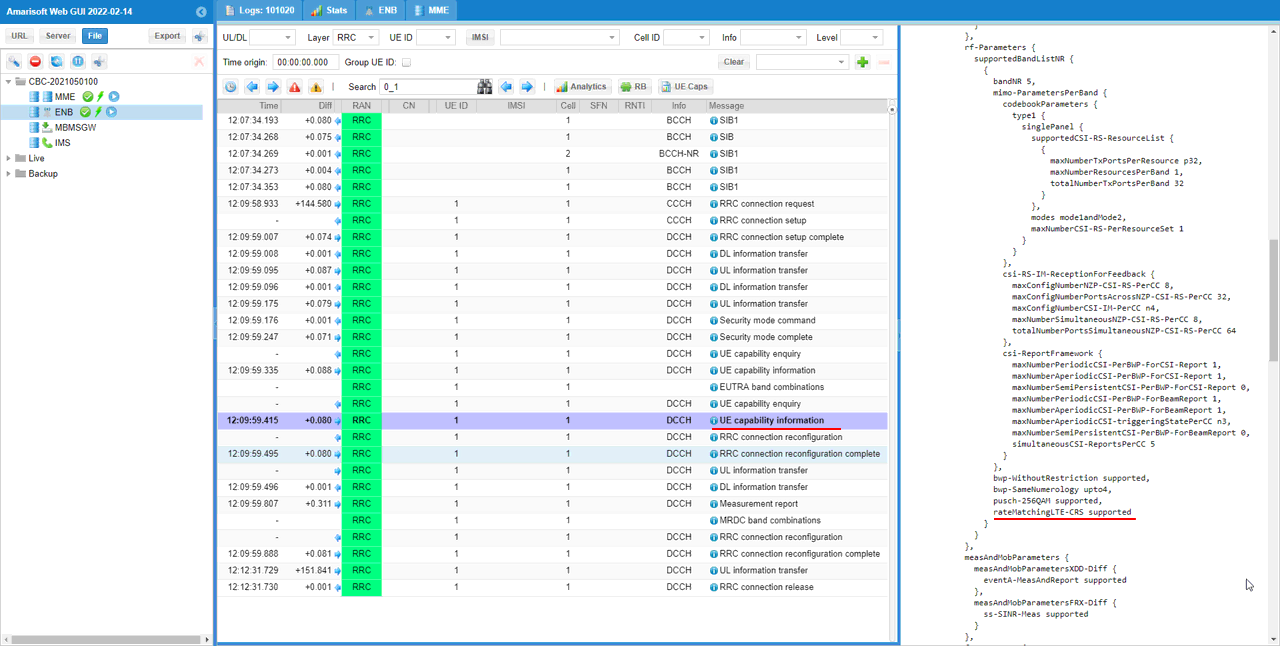
Confirm that UE support capability for DSS. The IE rateMatchingLTE-CRS indicates whether the UE supports DSS or Not.
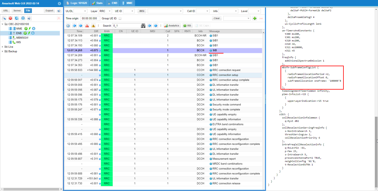
Then check if mbsfn is configured with IE mbsfn-SubframeConfigList in LTE SIB message. (MBSFN itself is not mandatory requirement for DSS, but we configured and used MBSFN as a part of DSS configuration in this tutorial).
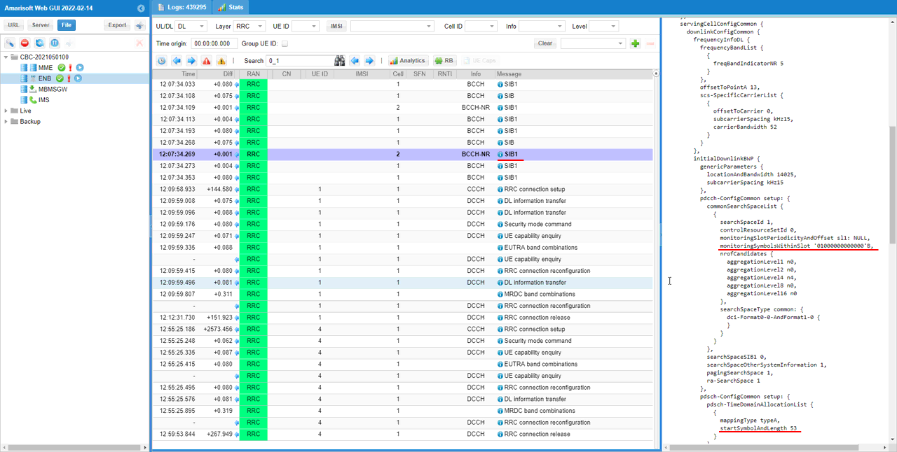
check monitoringSymbolswithinSlot and pdsch SLIV(startSymbolAndLength) and make it sure that they are not overlapping with LTE control channel region.
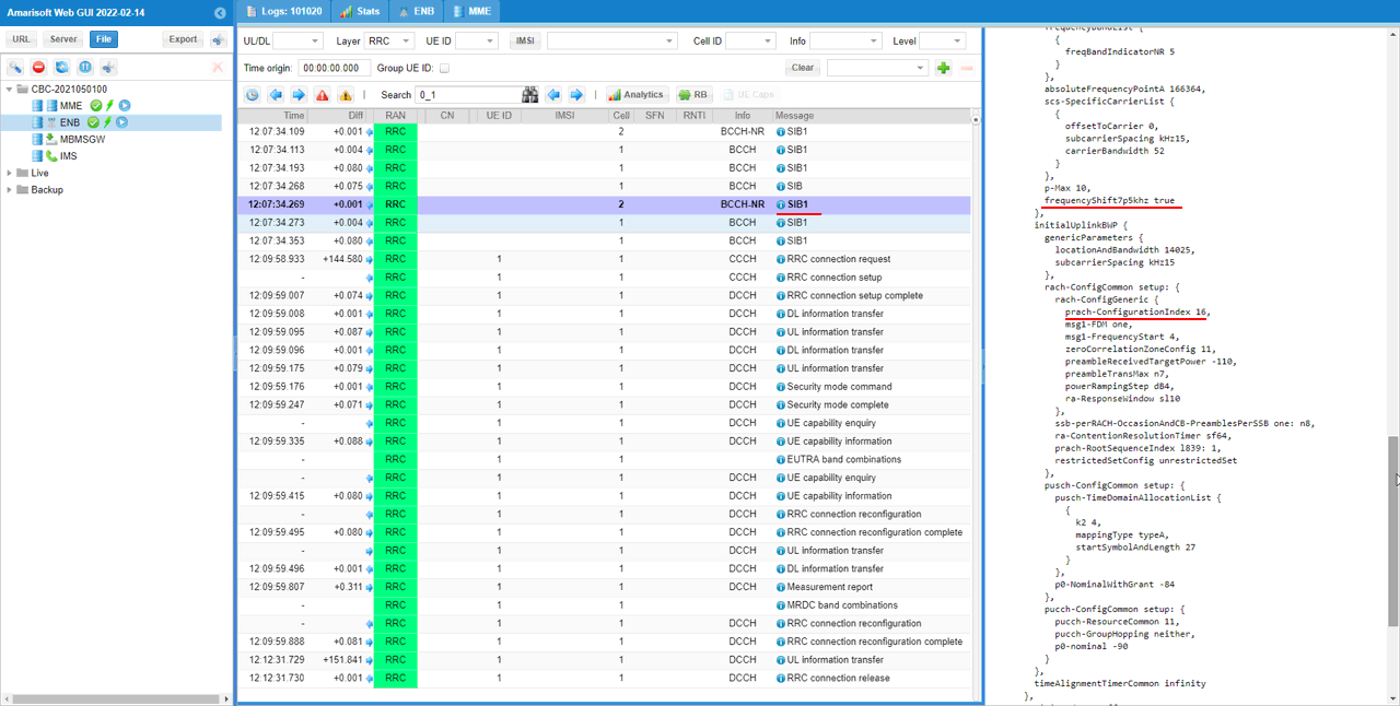
Check NR SIB1 message and see if frequencyShift7p5khz and prach-ConfigurationIndex are configured as set in the configuration file.
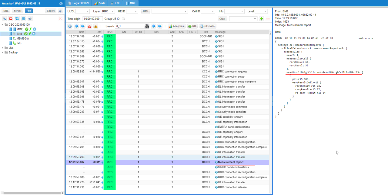
After UE power on and the completion of LTE initial attach, it is expected to get Measurement report for NR cell. If the measurement report for NR cell is recieved, it proceed to the next step.
now you see NR cell gets added as shown in spCellConfig IE in RRC Connection Reconfiguration message.
Check monitoringSymbolswithinSlot IE and make it sure that it is not overlapping with LTE control channel region.
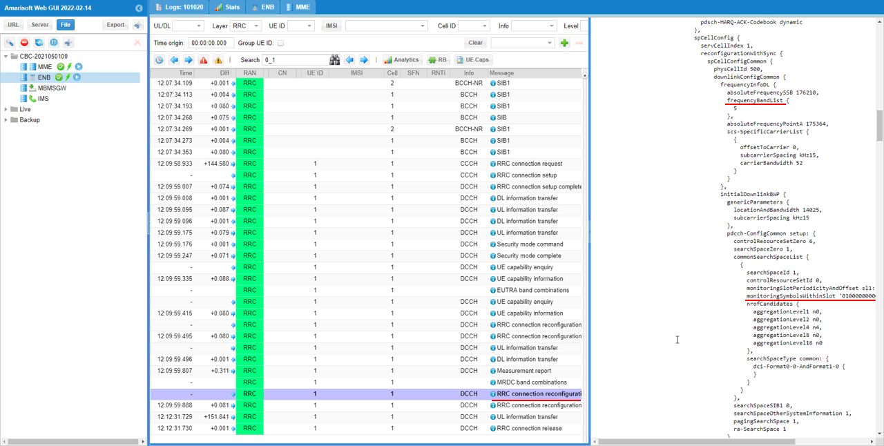
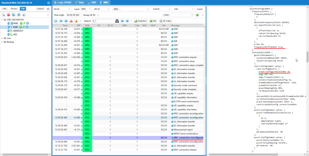
Check if frequencyShift7p5khz and prach-ConfigurationIndex are configured as set in the configuration file.
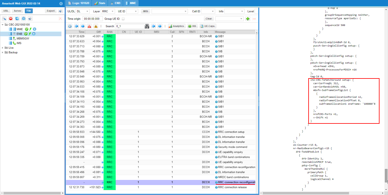
You see mbsfn is configured in lte-CRS-ToMatchAround IE.
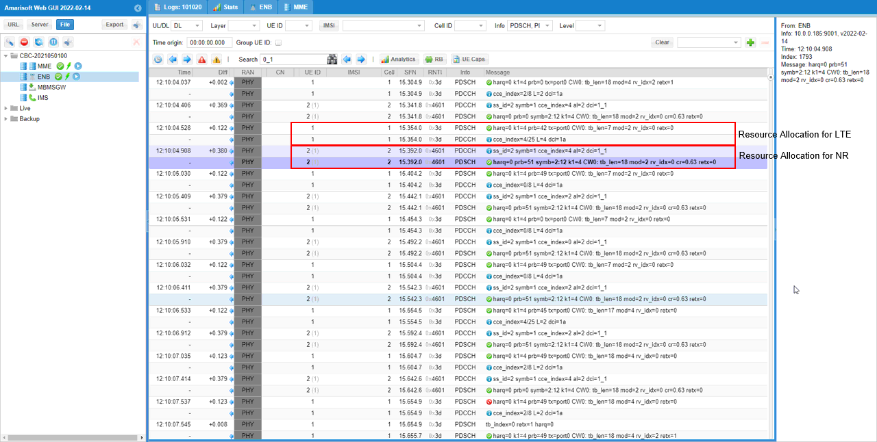
Now let's check on phy traffic. To check this more easily, let's filter out only the relative log info. I want to display LTE/NR control channel (PDCCH, PHICH, PUCCH) and traffic channels (PDSCH, PUSCH) only.
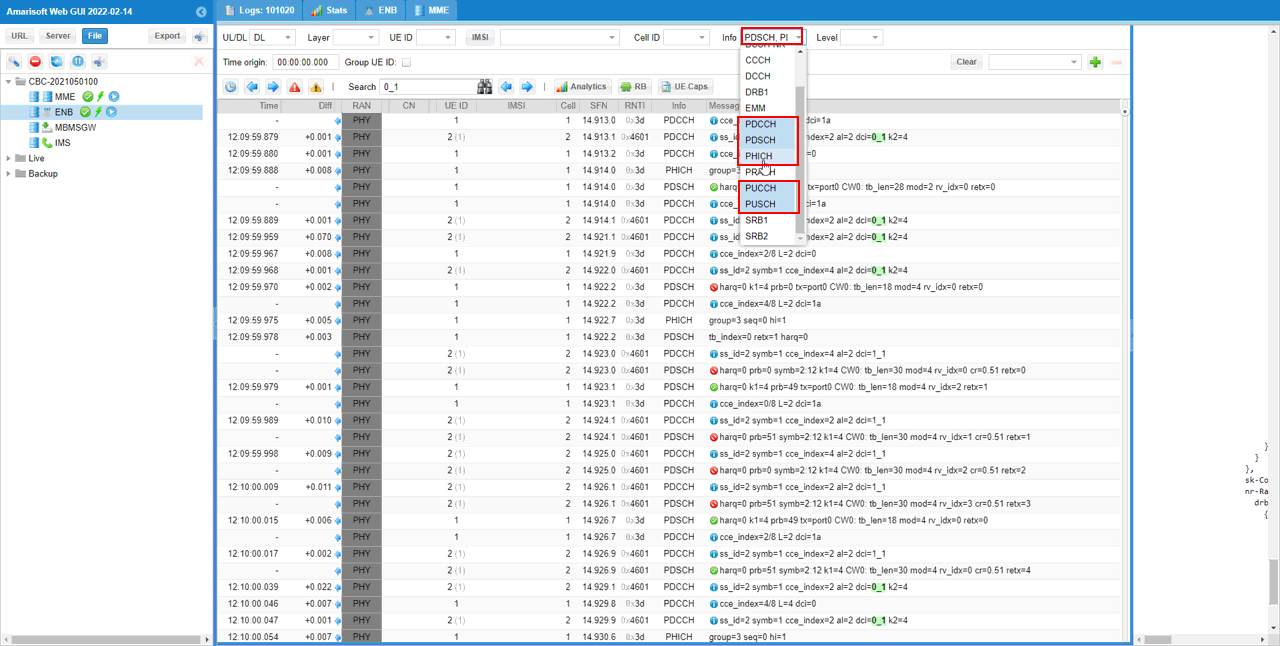
Now make it sure that you see control and traffic channel for both LTE and NR are going through.
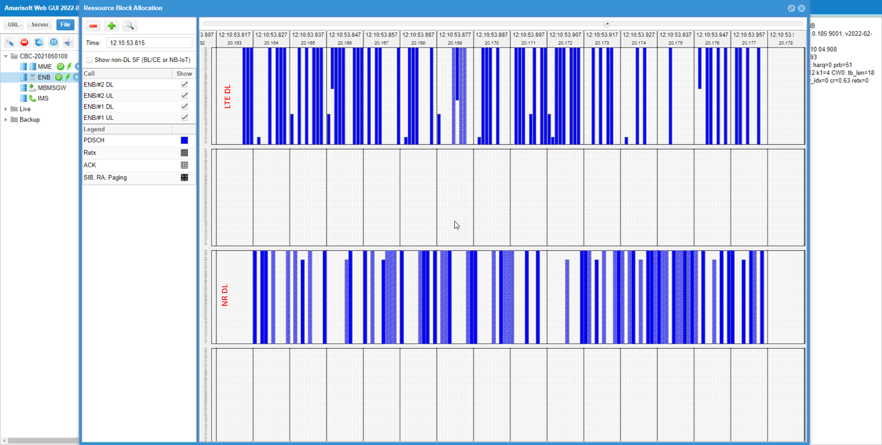
If you check RB map, you can check physical channel operation more easily and across wider time span.
Spectrum Analysis
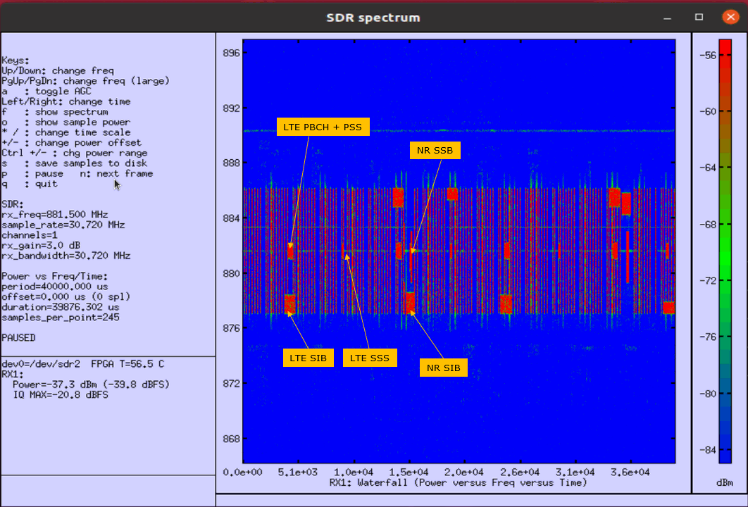
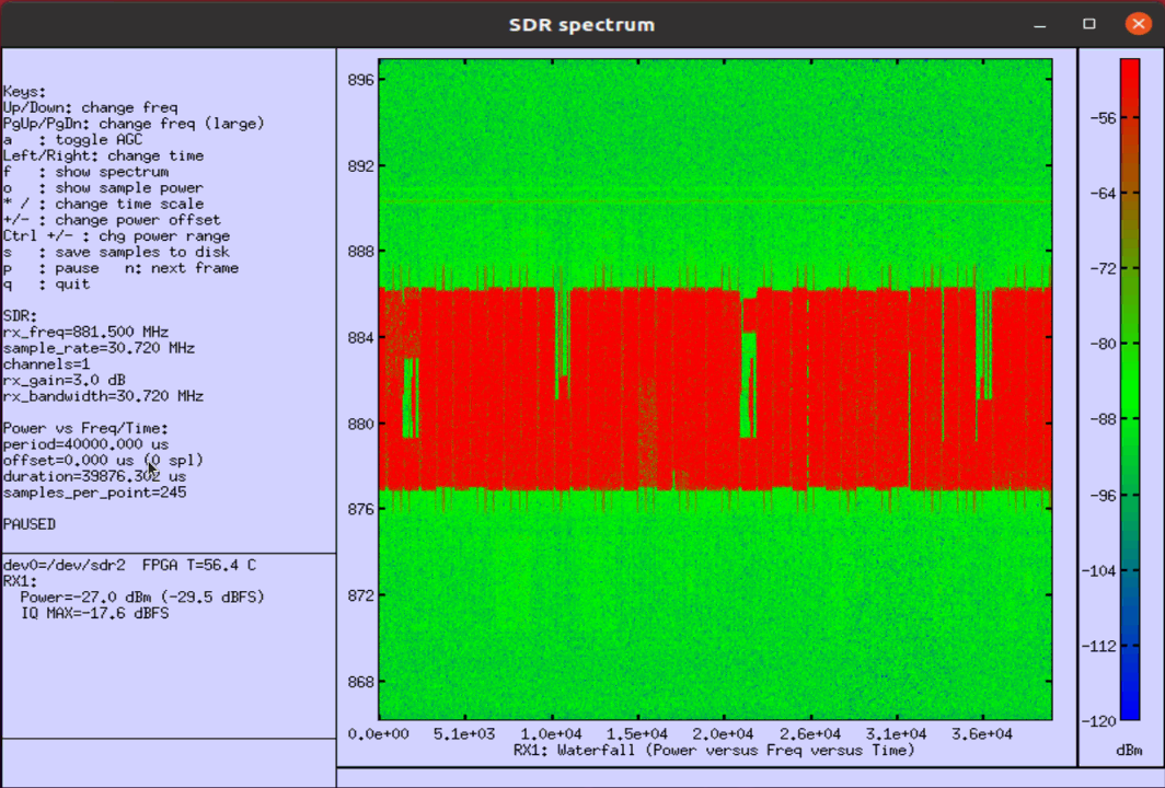
If you use the spectrum analyzer built into Amarisoft system, you can confirm on signal flow on physical layer/RF. Of course, you can use any other spectrum analyzer that support spectrogram. One tricky thing is that in most case the spectrogram show color coding based on signal power only, it does not provide any color coding based on the nature of the signal (e.g, PDCCH, PDSCH, SSB etc). So you should have detailed knowledge about the nature of the physical signal and exact positioning of those signals on the spectrogram.
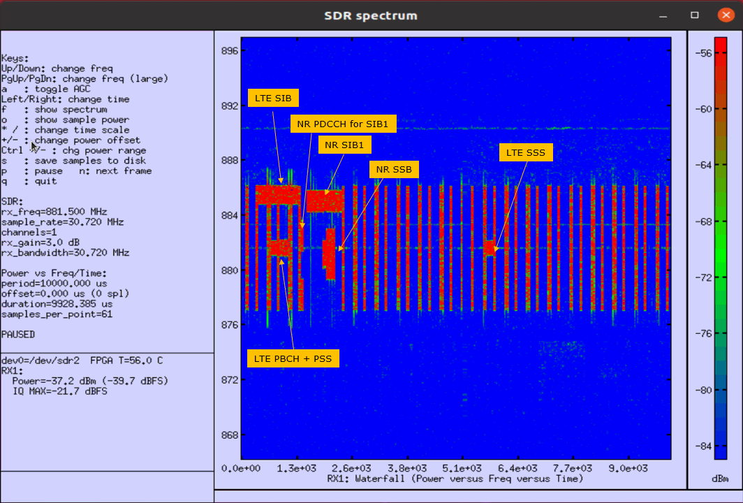
Amarisoft spectrogram(waterfall) allows zooming in time domain so that you can check the contents in more detail.
Following image shows the spectrogram for the case where full spectrum is scheduled for user data flow. It is hard (almost impossible) to know which part is LTE traffic or which part is NR traffic just looking at the spectrogram, but you can confirm on the overall utilization of the spectrum.
RRC / NAS Signaling
UE Capability Information (LTE)
: This is the UE Capability Information message sent by UE indicating the supportability of DSS. (
{
message c1: ueCapabilityInformation: {
rrc-TransactionIdentifier 0,
criticalExtensions c1: ueCapabilityInformation-r8: {
ue-CapabilityRAT-ContainerList {
{
rat-Type nr,
ueCapabilityRAT-Container {
accessStratumRelease rel15,
pdcp-Parameters {
...
},
rlc-Parameters {
...
},
mac-Parameters {
...
},
phy-Parameters {
phy-ParametersCommon {
...
},
phy-ParametersFRX-Diff {
...
},
phy-ParametersFR1 {
...
}
},
rf-Parameters {
supportedBandListNR {
{
bandNR 5,
mimo-ParametersPerBand {
codebookParameters {
type1 {
...
},
csi-RS-IM-ReceptionForFeedback {
...
},
csi-ReportFramework {
...
}
},
bwp-WithoutRestriction supported,
bwp-SameNumerology upto4,
pusch-256QAM supported,
rateMatchingLTE-CRS supported
}
}
},
measAndMobParameters {
...
},
featureSets {
...
}
},
...
SIB2 (LTE)
: This is the SIB2 message sent by eNB to support DSS. (
{
message c1: systemInformation: {
criticalExtensions systemInformation-r8: {
sib-TypeAndInfo {
sib2: {
radioResourceConfigCommon {
rach-ConfigCommon {
preambleInfo {
...
},
powerRampingParameters {
...
},
ra-SupervisionInfo {
...
},
...
},
bcch-Config {
...
},
pcch-Config {
...
},
prach-Config {
...
},
pdsch-ConfigCommon {
...
},
pusch-ConfigCommon {
...
},
pucch-ConfigCommon {
...
},
soundingRS-UL-ConfigCommon release: NULL,
uplinkPowerControlCommon {
...
},
ul-CyclicPrefixLength len1
},
ue-TimersAndConstants {
...
},
freqInfo {
...
},
mbsfn-SubframeConfigList {
{
radioframeAllocationPeriod n2,
radioframeAllocationOffset 0,
subframeAllocation oneFrame: '100000'B
}
},
...
plmn-InfoList-r15 {
{
upperLayerIndication-r15 true
}
}
},
,,
}
SIB1 (NR)
: This is the SIB1 message sent by gNB to support DSS. (
{
message c1: systemInformationBlockType1: {
cellSelectionInfo {
...
},
cellAccessRelatedInfo {
...
},
connEstFailureControl {
...
},
servingCellConfigCommon {
downlinkConfigCommon {
frequencyInfoDL {
frequencyBandList {
{
freqBandIndicatorNR 5
}
},
offsetToPointA 13,
scs-SpecificCarrierList {
{
offsetToCarrier 0,
subcarrierSpacing kHz15,
carrierBandwidth 52
}
}
},
initialDownlinkBWP {
genericParameters {
locationAndBandwidth 14025,
subcarrierSpacing kHz15
},
pdcch-ConfigCommon setup: {
commonSearchSpaceList {
{
searchSpaceId 1,
controlResourceSetId 0,
monitoringSlotPeriodicityAndOffset sl1: NULL,
monitoringSymbolsWithinSlot '01000000000000'B,
nrofCandidates {
aggregationLevel1 n0,
aggregationLevel2 n0,
aggregationLevel4 n4,
aggregationLevel8 n0,
aggregationLevel16 n0
},
searchSpaceType common: {
dci-Format0-0-AndFormat1-0 {
}
}
}
},
...
},
pdsch-ConfigCommon setup: {
pdsch-TimeDomainAllocationList {
{
mappingType typeA,
startSymbolAndLength 53
}
}
}
},
bcch-Config {
...
},
pcch-Config {
...
}
},
uplinkConfigCommon {
frequencyInfoUL {
frequencyBandList {
{
freqBandIndicatorNR 5
}
},
absoluteFrequencyPointA 166364,
scs-SpecificCarrierList {
{
offsetToCarrier 0,
subcarrierSpacing kHz15,
carrierBandwidth 52
}
},
p-Max 10,
frequencyShift7p5khz true
},
initialUplinkBWP {
genericParameters {
locationAndBandwidth 14025,
subcarrierSpacing kHz15
},
rach-ConfigCommon setup: {
rach-ConfigGeneric {
prach-ConfigurationIndex 16,
...
},
...
},
pusch-ConfigCommon setup: {
pusch-TimeDomainAllocationList {
{
k2 4,
mappingType typeA,
startSymbolAndLength 27
}
},
p0-NominalWithGrant -84
},
pucch-ConfigCommon setup: {
...
}
},
timeAlignmentTimerCommon infinity
},
n-TimingAdvanceOffset n0,
ssb-PositionsInBurst {
inOneGroup '10'H
},
...
},
ue-TimersAndConstants {
...
}
}
}
RrcConnectionReconfiguration (LTE)
: This is the RrcConnectionReconfiguration message sent by eNB to add NR1 with DSS capability. (
{
message c1: rrcConnectionReconfiguration: {
rrc-TransactionIdentifier 0,
criticalExtensions c1: rrcConnectionReconfiguration-r8: {
...
radioResourceConfigDedicated {
...
},
nonCriticalExtension {
nonCriticalExtension {
nonCriticalExtension {
nonCriticalExtension {
nonCriticalExtension {
nonCriticalExtension {
nonCriticalExtension {
nonCriticalExtension {
nr-Config-r15 setup: {
endc-ReleaseAndAdd-r15 FALSE,
nr-SecondaryCellGroupConfig-r15 {
rrc-TransactionIdentifier 0,
criticalExtensions rrcReconfiguration: {
secondaryCellGroup {
cellGroupId 1,
rlc-BearerToAddModList {
...
},
mac-CellGroupConfig {
...
},
physicalCellGroupConfig {
...
},
spCellConfig {
servCellIndex 1,
reconfigurationWithSync {
spCellConfigCommon {
physCellId 500,
downlinkConfigCommon {
frequencyInfoDL {
absoluteFrequencySSB 176210,
frequencyBandList {
5
},
absoluteFrequencyPointA 175364,
scs-SpecificCarrierList {
{
offsetToCarrier 0,
subcarrierSpacing kHz15,
carrierBandwidth 52
}
}
},
initialDownlinkBWP {
genericParameters {
locationAndBandwidth 14025,
subcarrierSpacing kHz15
},
pdcch-ConfigCommon setup: {
controlResourceSetZero 6,
searchSpaceZero 1,
commonSearchSpaceList {
{
searchSpaceId 1,
controlResourceSetId 0,
monitoringSlotPeriodicityAndOffset sl1: NULL,
monitoringSymbolsWithinSlot '01000000000000'B,
nrofCandidates {
aggregationLevel1 n0,
aggregationLevel2 n0,
aggregationLevel4 n4,
aggregationLevel8 n0,
aggregationLevel16 n0
},
searchSpaceType common: {
dci-Format0-0-AndFormat1-0 {
}
}
}
},
searchSpaceSIB1 0,
searchSpaceOtherSystemInformation 1,
pagingSearchSpace 1,
ra-SearchSpace 1
},
pdsch-ConfigCommon setup: {
pdsch-TimeDomainAllocationList {
{
mappingType typeA,
startSymbolAndLength 53
}
}
}
}
},
uplinkConfigCommon {
frequencyInfoUL {
frequencyBandList {
5
},
absoluteFrequencyPointA 166364,
scs-SpecificCarrierList {
{
offsetToCarrier 0,
subcarrierSpacing kHz15,
carrierBandwidth 52
}
},
p-Max 10,
frequencyShift7p5khz true
},
initialUplinkBWP {
genericParameters {
locationAndBandwidth 14025,
subcarrierSpacing kHz15
},
rach-ConfigCommon setup: {
rach-ConfigGeneric {
prach-ConfigurationIndex 16,
msg1-FDM one,
msg1-FrequencyStart 4,
zeroCorrelationZoneConfig 11,
preambleReceivedTargetPower -110,
preambleTransMax n7,
powerRampingStep dB4,
ra-ResponseWindow sl10
},
ssb-perRACH-OccasionAndCB-PreamblesPerSSB one: n8,
ra-ContentionResolutionTimer sf64,
prach-RootSequenceIndex l839: 1,
restrictedSetConfig unrestrictedSet
},
pusch-ConfigCommon setup: {
pusch-TimeDomainAllocationList {
{
k2 4,
mappingType typeA,
startSymbolAndLength 27
}
},
...
},
pucch-ConfigCommon setup: {
...
}
},
...
},
n-TimingAdvanceOffset n0,
ssb-PositionsInBurst shortBitmap: '1'H,
ssb-periodicityServingCell ms20,
dmrs-TypeA-Position pos3,
ssbSubcarrierSpacing kHz15,
ss-PBCH-BlockPower -25
},
...
},
rlf-TimersAndConstants setup: {
...
},
spCellConfigDedicated {
initialDownlinkBWP {
pdcch-Config setup: {
controlResourceSetToAddModList {
{
controlResourceSetId 2,
frequencyDomainResources '111111110000000000000000000000000000000000000'B,
duration 1,
cce-REG-MappingType nonInterleaved: NULL,
precoderGranularity sameAsREG-bundle
}
},
searchSpacesToAddModList {
{
searchSpaceId 2,
controlResourceSetId 2,
monitoringSlotPeriodicityAndOffset sl1: NULL,
monitoringSymbolsWithinSlot '01000000000000'B,
nrofCandidates {
aggregationLevel1 n4,
aggregationLevel2 n2,
aggregationLevel4 n1,
aggregationLevel8 n0,
aggregationLevel16 n0
},
searchSpaceType ue-Specific: {
dci-Formats formats0-1-And-1-1
}
}
}
},
pdsch-Config setup: {
dmrs-DownlinkForPDSCH-MappingTypeA setup: {
dmrs-AdditionalPosition pos1
},
...
}
},
firstActiveDownlinkBWP-Id 0,
uplinkConfig {
initialUplinkBWP {
pucch-Config setup: {
...
},
pusch-Config setup: {
...
},
srs-Config setup: {
...
}
},
firstActiveUplinkBWP-Id 0,
pusch-ServingCellConfig setup: {
}
},
pdcch-ServingCellConfig setup: {
},
pdsch-ServingCellConfig setup: {
xOverhead xOh6,
nrofHARQ-ProcessesForPDSCH n16
},
tag-Id 0,
lte-CRS-ToMatchAround setup: {
carrierFreqDL 312,
carrierBandwidthDL n50,
mbsfn-SubframeConfigList {
{
radioframeAllocationPeriod n2,
radioframeAllocationOffset 0,
subframeAllocation1 oneFrame: '100000'B
}
},
nrofCRS-Ports n1,
v-Shift n1
}
}
}
}
}
}
},
sk-Counter-r15 0,
nr-RadioBearerConfig1-r15 {
...
}