NR CG (Configured Grant)
This tutorial is to show you how to configure Configured Grant. Configured Grant is a mechanism that enable UL scheduling via RRC message and schedule PUSCH without DCI. Major user case and concept is very similar to SPS (Semi Persistent Scheduling) in LTE. In LTE, we used the same concept both in downlink and uplink, and name it as SPS for both downlink and uplink. But in NR, we call this mechanism as Configured Grant for Uplink and SPS for Downlink.
There are two types of CG defined in 3GPP called Type 1 and Type 2 which can be summarized as follows.
- Type 1 : UE is expected to transmit PUSCH as soon as it complete the processing of RRC message (e.g, RRCReconfiguration) confuring CG
- Type 2 : UE is expected to transmit PUSCH after it complete the processing of the RRC message and DCI trigger (DCI masked with CS-RNTI)
Table of Contents
Introduction
Configured Grant (CG) is an advanced uplink scheduling mechanism introduced in 5G NR (New Radio) to enhance uplink data transmission efficiency and reduce network signaling overhead. Unlike dynamic scheduling, where each uplink transmission requires explicit grant signaling via Downlink Control Information (DCI), Configured Grant enables the gNodeB (5G base station) to pre-configure the UE (User Equipment) with uplink transmission resources through RRC (Radio Resource Control) configuration. This allows the UE to transmit PUSCH (Physical Uplink Shared Channel) data autonomously at predetermined intervals, significantly lowering latency and improving support for services requiring predictable uplink resources, such as Ultra-Reliable Low-Latency Communication (URLLC) and massive Machine Type Communications (mMTC). Architecturally, Configured Grant leverages NR’s flexible slot-based structure and advanced scheduling policies, supporting two main types: Type 1, which allows immediate autonomous transmission after RRC configuration, and Type 2, which requires an additional DCI trigger before transmission. This approach builds upon and extends the Semi-Persistent Scheduling (SPS) concept from LTE, where SPS was used for both uplink and downlink, but in NR, Configured Grant is specific to uplink while SPS is dedicated to downlink. The introduction of Configured Grant addresses the need for scalable, low-latency data services in the evolving 5G ecosystem, playing a critical role in enabling new applications and use-cases that demand more deterministic and efficient uplink scheduling.
-
Context and Background
- Configured Grant is a 5G NR uplink scheduling feature standardized by 3GPP, designed to enable autonomous PUSCH transmissions by UEs.
- It is conceptually similar to LTE’s Semi-Persistent Scheduling but is tailored for NR’s flexible architecture and enhanced uplink requirements.
- CG reduces the reliance on frequent DCI grants for every uplink transmission, optimizing both network resource usage and air interface signaling.
-
Relevance and Importance of the Tutorial Topic
- As 5G adoption accelerates, understanding advanced scheduling mechanisms like Configured Grant is essential for engineers and practitioners working on NR systems, particularly those focusing on URLLC, mMTC, and other latency-sensitive services.
- Configured Grant supports improved uplink efficiency, lower latency, and greater scalability, all of which are pivotal for next-generation wireless applications.
- Mastery of CG configuration and operation is increasingly important for optimizing network performance and supporting emerging 5G use-cases.
-
Learning Outcomes
- Gain a comprehensive understanding of Configured Grant concepts, types, and operational principles in 5G NR.
- Learn how to configure Type 1 and Type 2 CG, including their triggering mechanisms and typical use scenarios.
- Understand the architectural differences between Configured Grant and dynamic scheduling, as well as its relationship to LTE SPS.
- Acquire the knowledge necessary to implement and troubleshoot CG features in practical NR deployments.
-
Prerequisite Knowledge and Skills
- Familiarity with 5G NR architecture, RRC protocols, and uplink transmission processes.
- Understanding of basic LTE/NR scheduling concepts, including DCI, PUSCH, and SPS.
- Experience with 3GPP specifications and radio interface configuration is recommended for deeper comprehension.
Summary of the Tutorial
This tutorial covers low-layer testing procedures for verifying Configured Grant (CG) Type 1 and Type 2 Immediate in NR SA (Standalone) mode, focusing on single BWP scenarios. The procedures utilize Amarisoft test equipment, and can be performed either with a commercial UE (Setup A) or the Amarisoft UEsim (Setup B). The summary below outlines the test methodologies, configuration steps, and execution flow for both test scenarios.
-
Test Setup
- Use the SIM card provided with the system.
- For custom configurations, refer to the linked Configuration Guide.
- Two hardware setups:
- Setup A: Commercial UE as DUT
- Setup B: Amarisoft UEsim as DUT (used in this tutorial)
-
Key Configuration Parameters
- Configure configured_grant and related parameters (e.g., tf_precoding, mcs_table, rbg_size, periodicity, configuration_type, etc.) in the gNB configuration.
- Optionally enable enhanced_skip_uplink_tx_configured_enabled as needed.
-
Test 1: Configured Grant - Type 1 with Single BWP
-
Configuration Steps:
- Modify and use gnb-sa-cg.cfg on the gNB (Callbox), based on the default gnb-sa.cfg.
- Modify and use drb_nr_cg.cfg for DRB configuration.
- For UEsim, modify and use ue-nr-sa-cg.cfg (set as_release to 16 or higher).
- In the gNB configuration, under configured_grant, set configuration_type to specify CG Type 1, assign physical resources with l_crb, l_crb_max, mcs, and set periodicity for PUSCH transmission interval.
- In DRB configuration, set need_sps to "ul" for the target QCI to apply CG.
-
Test Execution:
- Start LTE service on the callbox and verify cell configuration with cell and cell phy commands.
- Power on the UE/UEsim device.
- Wait for initial attach completion; verify UL traffic scheduled by configured grant (PUSCH transmissions should occur at the configured interval without DCI triggering).
-
Log Analysis:
- Check logs to ensure UE capability for configuredUL-GrantType1 is reported.
- Confirm that after RRC Reconfiguration with CG, the UE transmits PUSCH at the expected periodicity (e.g., every 10ms if periodicity is set to sym20x14).
-
Configuration Steps:
-
Test 2: Configured Grant - Type 2 Immediate with Single BWP
-
Configuration Steps:
- Modify and use gnb-sa-cg-type2-immediate.cfg on the gNB (Callbox), based on the default gnb-sa.cfg.
- Use drb_nr_cg.cfg as in Test 1 for DRB configuration.
- For UEsim, use ue-nr-sa-cg.cfg (no change from Test 1; set as_release to 16 or higher).
- In the gNB configuration, set configured_grant parameters as above, but specify configuration_type for CG Type 2 Immediate.
- In DRB configuration, set need_sps to "ul" for the target QCI.
-
Test Execution:
- Start LTE service on the callbox; verify cell configuration as before.
- Power on UE/UEsim device.
- Wait for initial attach to complete; check for UL traffic scheduled by configured grant.
-
Log Analysis:
- Ensure UE capability for configuredUL-GrantType2 is reported.
- Verify that after RRC Reconfiguration, an initial DCI (0_1 UL Grant) is seen, followed by periodic PUSCH transmissions per the configured periodicity.
-
Configuration Steps:
Overall Methodology:
- Configuration of gNB and UE/UEsim parameters to enable and test Configured Grant Type 1 and Type 2 Immediate.
- Verification of correct operational behavior by monitoring log files and command outputs to ensure that PUSCH transmissions occur according to the configuration (with or without DCI as specified by CG type).
- Logs are used to confirm that the UE advertises the necessary capabilities and that the configured grants are applied and functioning as expected.
Test Setup
Test setup for this tutorial is as shown below. This is just for low layer testing, you may not need any complicated IP layer setup.
- SIM Card used in this tutorial is the one delivered with the system as it is.
- If you want to change the configuration, The tutorial Configuration Guide would help
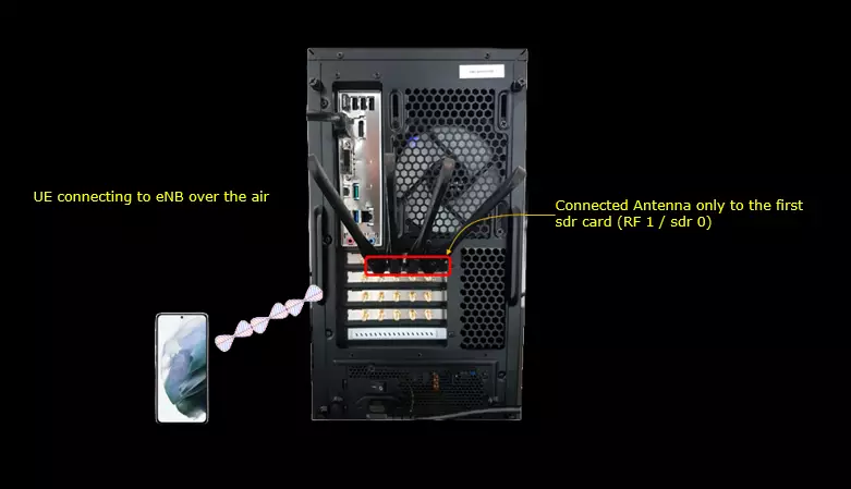
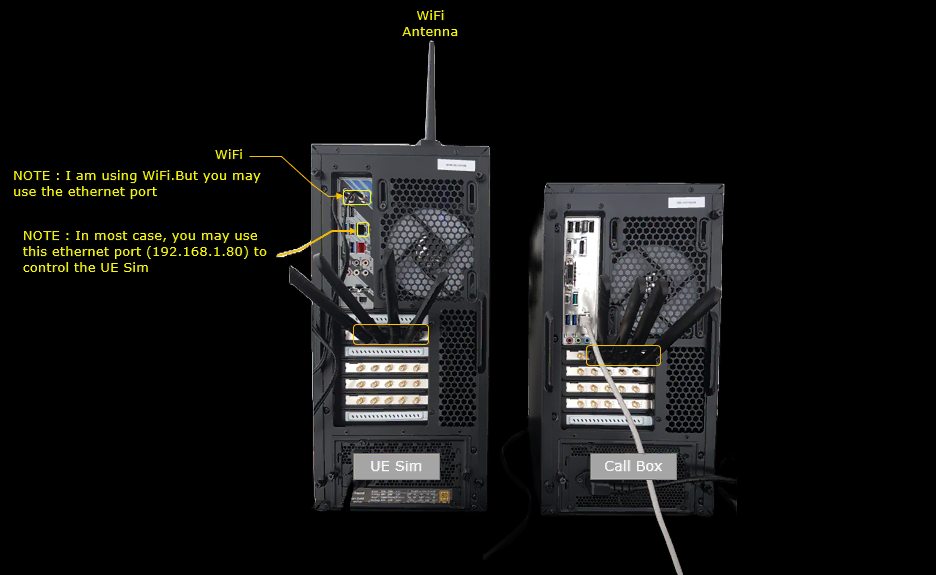
If you have a commercial UE that support UE assistance information with Release Preference, you can use the Setup A. If you don't have any commercial UE supporting this feature but have Amarisoft UEsim you can use Setup B. In this Test, Setup B is used.
Setup A
This is the setup where you use a commercial UE as DUT.
Setup B
This is the setup where you use a commercial Amarisoft UEsim as DUT.
Key Configuration Parameters
Followings are important configuration parameters for this tutorial. You may click on the items for the descriptions from Amarisoft documents.
- configured_grant : Under this link, all the parameters listed below are described.
- tf_precoding
- mcs_table
- rbg_size
- ra_type
- dynamic_beta_offsets
- dmrs
- tpmi
- mcs
- n_layer
- l_crb
- periodicity
- configuration_type
- max_retrans
- dtx_snr_threshold
- skip_uplink_tx_snr_threshold
- type2_deact_no_data_threshold
- l_crb_max
- rb_start
- p0_nominal_without_grant
- enhanced_skip_uplink_tx_configured_enabled
Test 1 : Configured Grant - Type 1 with Single BWP
This test is to show how to configure and verify the CG(Configured Grant) type 1. In CG Type 1, UE is expected to send PUSCH after RRCReconfiguration for CG without DCI Triggering.
Configuration
The configuration shown here is common configuration for all the subtests belonging to Test 1
I have used gnb-sa-cg.cfg which is copied and modified from gnb-sa.cfg on Callbox (gNB) and drb_nr_cg.cfg which is copied and modified from drb_nr.cfg

I am using the default mme-ims.cfg without any modification.
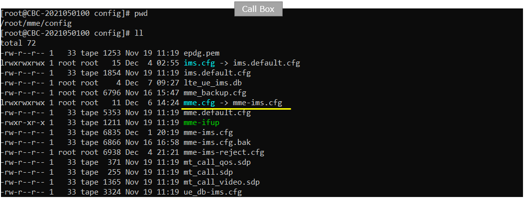
On UEsim, I used ue-nr-sa-cg.cfg which has been copied and modified from ue-nr-sa.cfg (

gnb-sa-cg.cfg is configured as follows.
In gNB configuration, you need to configure the parameter configured_grant. Within the configured_grant object, you need to specify CG type by the parameter configuration_type , assign physical resources by the parameters l_crb,l_crb_max,mcs and specify the PUSCH transmission interval by setting the parameter periodicity.
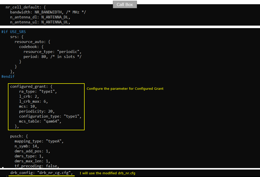
drb_nr_cg.cfg is configured as follows.
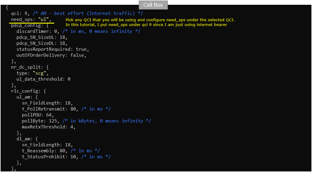
In drb configuration, you need to set need_sps to "ul" for the specific QCI you want to apply CG(configured grant). You can pick any QCI in this configuration to apply configured grant.
ue-nr-sa-cg.cfg is configured as shown below. (
The only configuration that you need to set in UEsim is to set as_release to 16 or higher.

Perform the Test
Run lte service on callbox and check 'cell' and 'cell phy' command to see if the cell is configured as you intended.

Power on UE.

Wait until the DUT complete the initial attach. You can confirm UL traffic scheduled by CG (Configured Grant) here as well. In case of PUSCH by configured grant, traffic is printed but mcs is not printed.

Log Analysis
Following is the log snapshot that are involved in Configured Grant
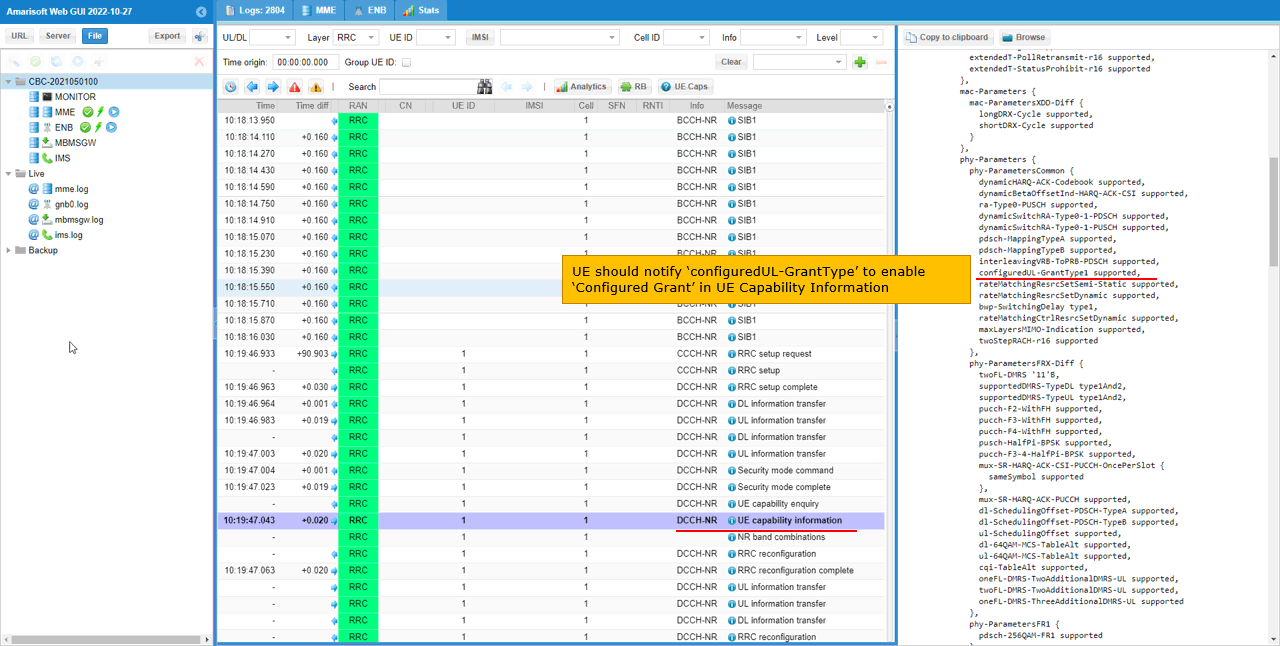
Make it sure that UE support configured grant as shown in the UE capability Information. UE should notify "configuredUL-GrantType1 supported" for gNB to apply the CG (configured grant).
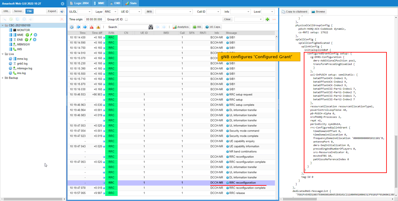
Once UE notify it support Configured Grant, then gNB configures Configured Grant. You see all the necessary scheduling information (i.e, rrc-ConfiguredUplinkGrant) and DMRS(cg-DMRS-Configuration) and UCI(uci-OnPUSCH Setup) in this setup.
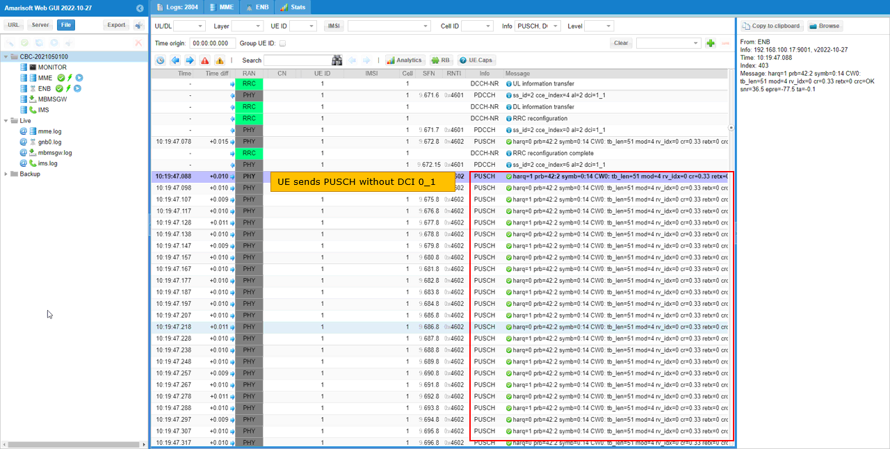
After the RRC Reconfiguration with CG, you would see that PUSCH is transmitted at every 10ms without any DCI grant. This is because the periodicity in rrc is set to sym20x14 which corresponds to 20 slots.
Test 2 : Configured Grant - Type 2 Immediate with Single BWP
This test is to show how to configure and verify the CG(Configured Grant) type 2 Immediate. In CG Type 2 Immediate, UE is expected to send PUSCH after RRCReconfiguration for CG and DCI Triggering.
Configuration
The configuration shown here is common configuration for all the subtests belonging to Test 2
I have used gnb-sa-cg-type2-immediate.cfg which is copied and modified from gnb-sa.cfg on Callbox (gNB) and drb_nr_cg.cfg which is copied and modified from drb_nr.cfg

I am using the default mme-ims.cfg without any modification.
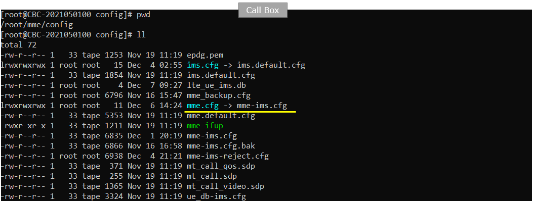
On UEsim, I used ue-nr-sa-cg.cfg which has been copied and modified from ue-nr-sa.cfg (

gnb-sa-cg-type2-immediate.cfg is configured as follows.
In gNB configuration, you need to configure the parameter configured_grant. Within the configured_grant object, you need to specify CG type by the parameter configuration_type , assign physical resources by the parameters l_crb,l_crb_max,mcs and specify the PUSCH transmission interval by setting the parameter periodicity.
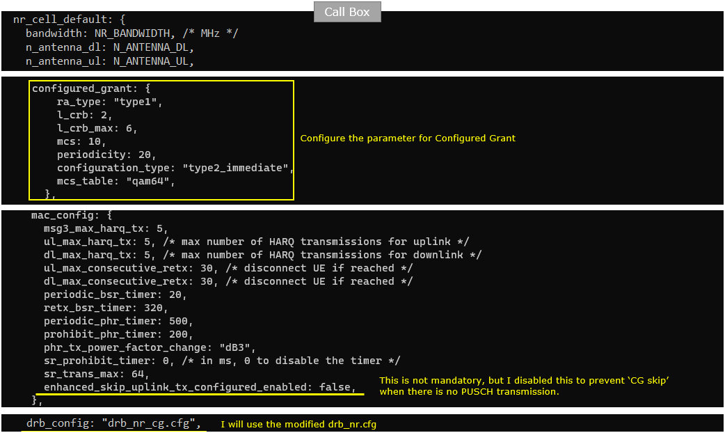
drb_nr_cg.cfg is configured as follows.
In drb configuration, you need to set need_sps to "ul" for the specific QCI you want to apply CG(configured grant). You can pick any QCI in this configuration to apply configured grant.
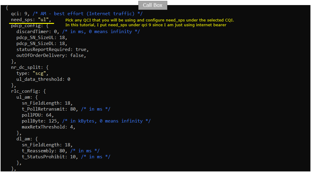
ue-nr-sa-cg.cfg is configured as shown below. (

Perform the Test
Run lte service on callbox and check 'cell' and 'cell phy' command to see if the cell is configured as you intended.

Power on UE.

Wait until the DUT complete the initial attach. You can confirm UL traffic scheduled by CG (Configured Grant) here as well. In case of PUSCH by configured grant, traffic is printed but mcs is not printed.

Log Analysis
Following is the log snapshot that are involved in Configured Grant
Make it sure that UE support configured grant as shown in the UE capability Information. UE should notify "configuredUL-GrantType2 supported" for gNB to apply the CG (configured grant) with type 2.
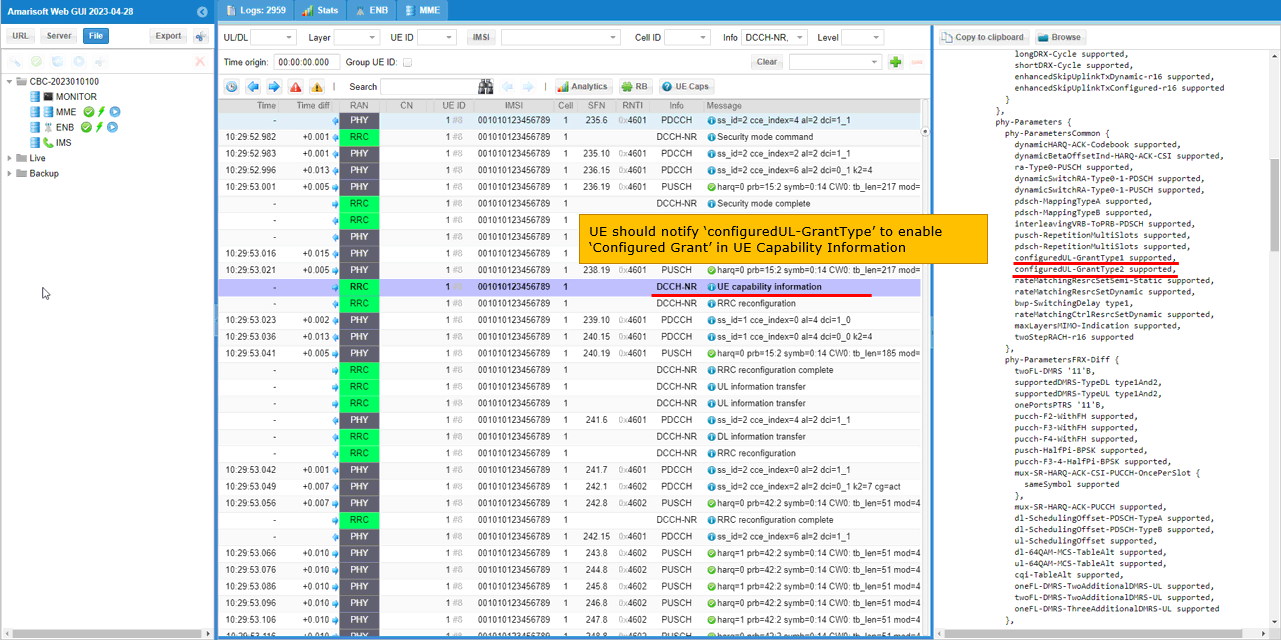
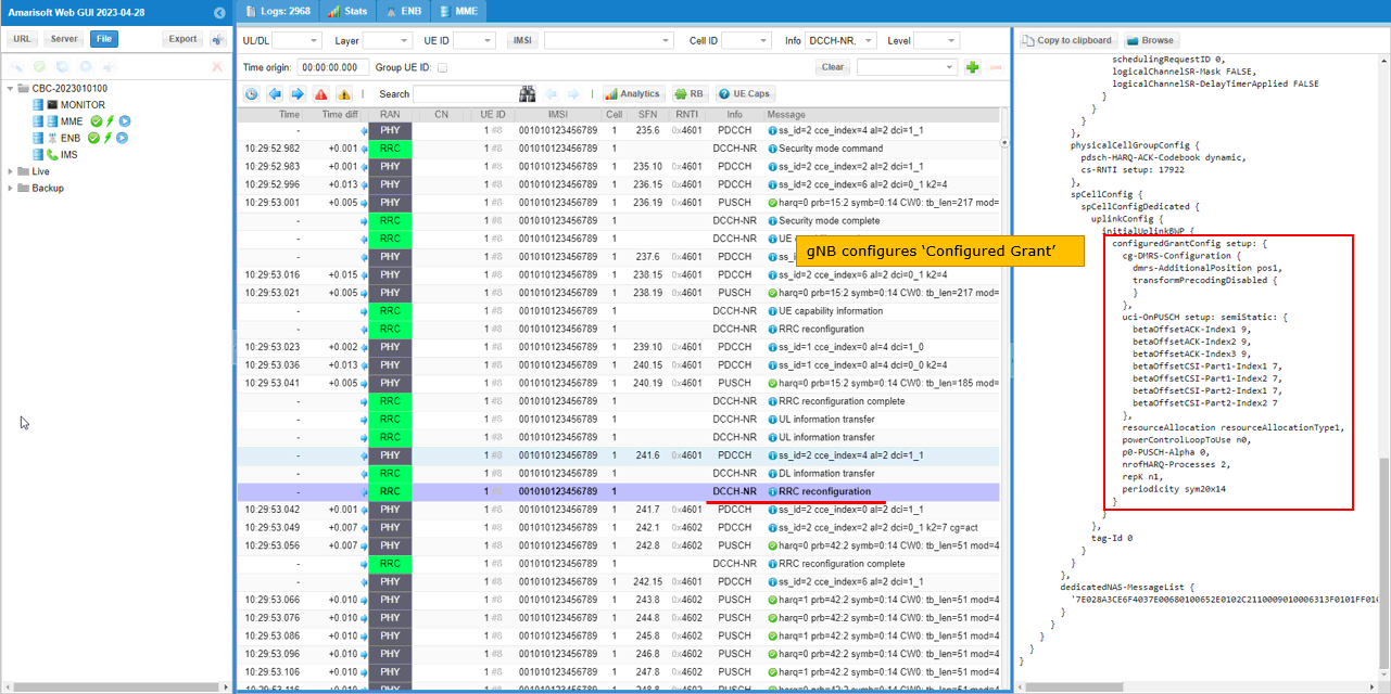
Once UE notify it support Configured Grant, then gNB configures Configured Grant. You see all the necessary information DMRS(cg-DMRS-Configuration) and UCI(uci-OnPUSCH Setup) in this setup. In this case, Grant Information (i.e, PUSCH Scheduling) is not configured because the information will be sent via the CG trigger (i.e, DCI).
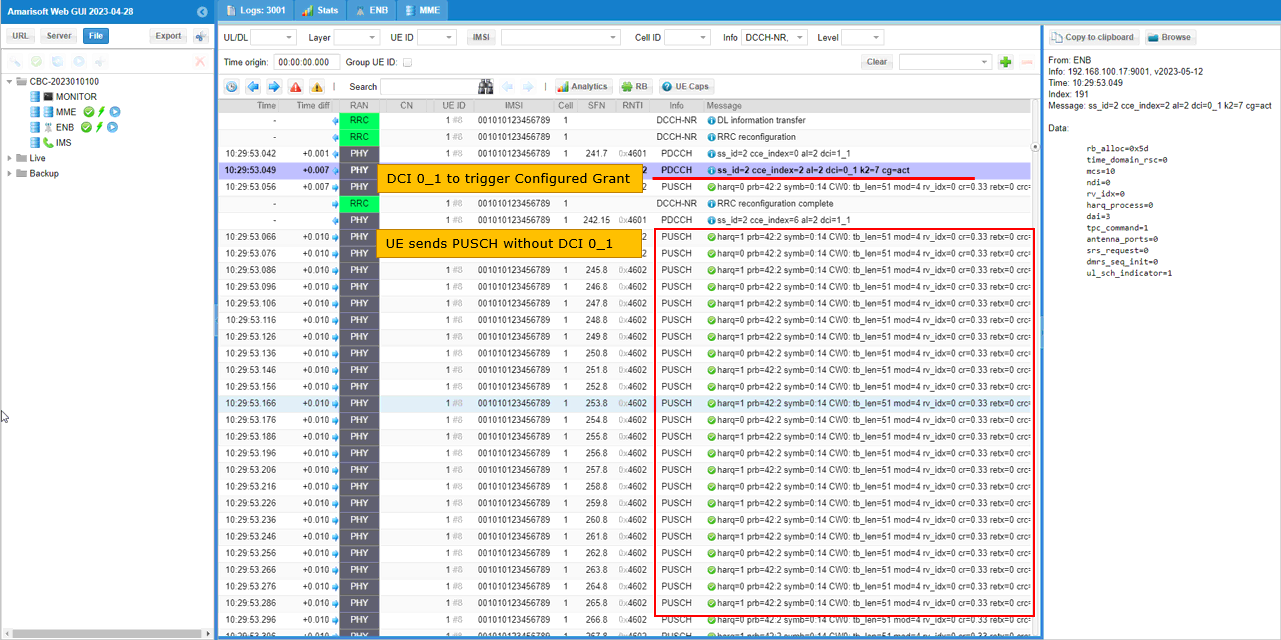
After the RRC Reconfiguration with CG, first you see a DCI 0_1 (UL Grant) first and then you would see that PUSCH is transmitted at every 10ms without any DCI grant. This is because the periodicity in rrc is set to sym20x14 which corresponds to 20 slots.
RRC / NAS Signaling
RrcReconfiguration (SA)
: This is RrcReconfiguration containing CG configurations
{
message c1: rrcReconfiguration: {
rrc-TransactionIdentifier 0,
criticalExtensions rrcReconfiguration: {
radioBearerConfig {
srb-ToAddModList {
{
srb-Identity 2
}
},
drb-ToAddModList {
{
...
}
}
},
nonCriticalExtension {
masterCellGroup {
...
},
physicalCellGroupConfig {
...
},
spCellConfig {
spCellConfigDedicated {
uplinkConfig {
initialUplinkBWP {
configuredGrantConfig setup: {
cg-DMRS-Configuration {
dmrs-AdditionalPosition pos1,
transformPrecodingDisabled {
}
},
uci-OnPUSCH setup: semiStatic: {
betaOffsetACK-Index1 9,
betaOffsetACK-Index2 9,
betaOffsetACK-Index3 9,
betaOffsetCSI-Part1-Index1 7,
betaOffsetCSI-Part1-Index2 7,
betaOffsetCSI-Part2-Index1 7,
betaOffsetCSI-Part2-Index2 7
},
resourceAllocation resourceAllocationType1,
powerControlLoopToUse n0,
p0-PUSCH-Alpha 0,
nrofHARQ-Processes 2,
repK n1,
periodicity sym20x14,
rrc-ConfiguredUplinkGrant {
timeDomainOffset 8,
timeDomainAllocation 0,
frequencyDomainAllocation '000000000001011101'B,
antennaPort 0,
dmrs-SeqInitialization 0,
precodingAndNumberOfLayers 0,
srs-ResourceIndicator 0,
mcsAndTBS 10,
pathlossReferenceIndex 0
}
}
}
},
tag-Id 0
}
}
},
dedicatedNAS-MessageList {
...
}
}
}
}