LTE MOCN
The purpose of this tutorial is to show you how to configure and test LTE MOCN. MOCN stands for Multiple Operator Core Network and it is a type of network sharing technology. There are some of key features to be noted in this technology
- A RAN is shared by multiple operators and the core network would be run/maintained by different operators
- The RAN (the shared RAN) should be broadcasting multiple PLMNs
With this tutorial, you would also learn how to connect one eNB to different MMEs. Since the configuration is pretty complicated, it would be good to have some big picture of the test concept and the configuration. It is illustrated below. When you follow through the configuration section, try to associate each configuration files/parameters to this diagram, otherwise you may easily get lost.
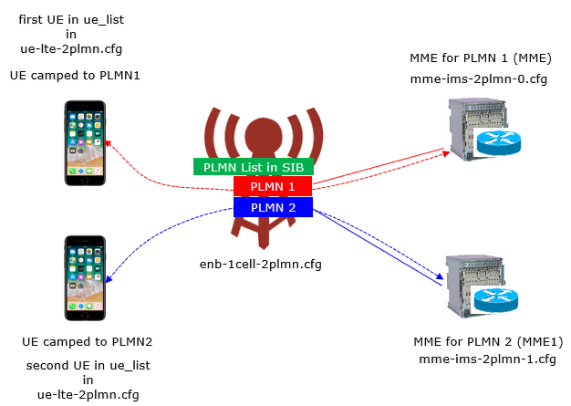
Table of Contents
Introduction
Multiple Operator Core Network (MOCN) is a sophisticated network sharing solution standardized in 3GPP to enable multiple mobile network operators (MNOs) to share a single Radio Access Network (RAN) infrastructure while maintaining independent core network operations. In the context of Long Term Evolution (LTE) networks, MOCN facilitates significant reductions in capital and operational expenditures by allowing operators to jointly utilize eNodeBs and spectrum resources, thereby improving resource utilization and accelerating network deployments. Architecturally, a shared RAN broadcasts multiple Public Land Mobile Network (PLMN) identifiers, enabling user equipment (UE) from different operators to access their respective core network entities—such as Mobility Management Entities (MMEs) and Serving Gateways (S-GWs)—over a common radio interface. The eNodeB is configured to recognize and route signaling and data traffic to the appropriate core network based on the selected PLMN, ensuring logical separation of subscriber traffic and operator-specific policies. MOCN plays a critical role in expanding coverage, especially in rural or less dense environments, fostering industry collaboration, and supporting increasingly complex service requirements. This tutorial introduces the practical aspects of configuring and testing LTE MOCN, focusing on the technical steps required to connect a single eNodeB to multiple operator core networks, as well as best practices for managing the associated configuration complexity. By understanding the underlying architecture and configuration principles, network engineers can effectively deploy and maintain shared LTE networks that are robust, scalable, and compliant with multi-operator environments.
-
Context and Background
- MOCN is a 3GPP-defined technology that enables multiple operators to share a common LTE RAN while maintaining independent core networks.
- It is widely used to optimize network resources, accelerate rollout, and reduce costs in both urban and rural deployment scenarios.
- The shared RAN broadcasts multiple PLMNs, allowing UEs to select their subscribed operator's network for connectivity.
-
Relevance and Importance
- MOCN addresses the increasing demand for efficient spectrum usage and network infrastructure by fostering collaboration among operators.
- It is essential for operators seeking to expand coverage or capacity without duplicating physical infrastructure.
- Understanding MOCN is crucial for professionals involved in modern LTE network design, deployment, and optimization.
-
Tutorial Objectives and Learning Outcomes
- Comprehend the architectural principles and operational mechanisms of LTE MOCN.
- Gain hands-on experience in configuring an eNodeB to interconnect with multiple MMEs from different core networks.
- Develop the ability to interpret and manage complex configuration files and parameters relevant to multi-operator network sharing.
- Acquire troubleshooting skills for common issues encountered in MOCN deployments.
-
Prerequisite Knowledge and Skills
- Familiarity with LTE network architecture, including eNodeB, EPC elements, and PLMN concepts.
- Basic understanding of network configuration procedures and parameter management.
- Experience with network testing tools and methodologies is helpful but not mandatory.
Summary of the Tutorial
This tutorial outlines the step-by-step procedures and methodologies for configuring, executing, and analyzing a Multi-Operator Core Network (MOCN) test scenario using a callbox setup with two MMEs, a single eNB, and simulated or commercial UEs. The focus is on validating correct configuration, operation, and signaling for supporting two PLMNs in a single LTE cell, as well as confirming proper UE attachment and network registration behaviors.
-
Test Setup:
- Two MME instances are run within the callbox: MME 0 with LTE service, MME 1 launched manually.
- Configuration and connectivity are established between the eNB, both MMEs, and two UEs (simulated or commercial).
-
Configuration Procedures:
-
UE Simulator:
- Use ue-lte-2plmn.cfg (modified from ue.default.cfg) to configure two UEs.
- Set multi_ue: true to enable simulation of two UEs.
- Set preferred_plmn_list and IMSI for each UE to camp on different PLMNs (00101 and 00102).
-
eNB:
- Use enb-1cell-2plmn.cfg (modified from enb.default.cfg).
- Add multiple mme_addr entries for both MMEs (127.0.1.100 for MME 0, 127.0.1.101 for MME 1).
-
MME 0 & MME 1:
- Use mme-ims-2plmn-0.cfg and mme-ims-2plmn-1.cfg (modified from mme-ims.cfg).
- Configure non-overlapping IP address pools for each PDN type ("default", "internet", "ims", "sos") per MME.
- Adjust plmn, com_addr, and gtp_addr to avoid overlaps between MMEs.
-
UE Database:
- Use ue_db-ims-2plmn.cfg to define USIM parameters for two UEs, each with a unique IMSI and PLMN.
-
OTS Component:
- Use ots-2mme.cfg to launch the second MME by creating a new "MME1" component associated with mme-ims-2plmn-1.cfg.
-
UE Simulator:
-
Test Execution Steps:
- Verify cell configuration using cell phy and cell commands.
- Check S1 connection status on eNB; wait for both MMEs to establish S1 connections (~30 seconds).
- Start eNB trace logging for further analysis.
- Power on each UE sequentially (either simulated via UEsim or commercial devices).
- Confirm each UE camps on the intended PLMN/cell as per configuration.
- Check connected UEs list in the eNB and verify both UEs are detected (note: idle UEs may not show).
- At the MME side, confirm each UE is assigned an IP address and registered under the correct PLMN.
-
Log Analysis Methodology:
- Collect logs from all relevant components (eNB, both MMEs), enabling full logging for RRC, NAS, and core network elements.
- Use filters for NAS, RRC, and S1AP to focus on MOCN-related signaling.
- Verify S1AP is established for both MMEs.
- Check SIB1 broadcasts both configured PLMNs.
- Confirm S1AP setup and responses for both MMEs, focusing on correct pLMNIdentity and broadcastPLMNs values.
- Trace attach procedures for each UE, confirming correct IMSI, IP assignment, and correct PLMN registration.
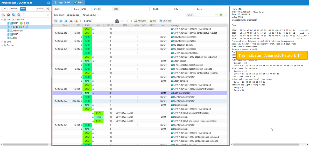
- Inspect ESM Information messages for network name consistency with configuration.
-
Signaling Checks:
- SIB1: Ensure eNB broadcasts both PLMNs as per configuration in the SIB1 message structure.
- EMM Information: Confirm that EMM Information message correctly transmits network name and related parameters to the UE.
-
Additional Tips:
- Use online tools for decoding network names from raw data fields for easier verification of network name elements.
The documented methodology ensures a comprehensive approach for validating MOCN configuration and operation, from initial setup through signaling verification and log analysis, focusing on the ability of the system to support UEs from different PLMNs within a shared radio environment.
Test Setup
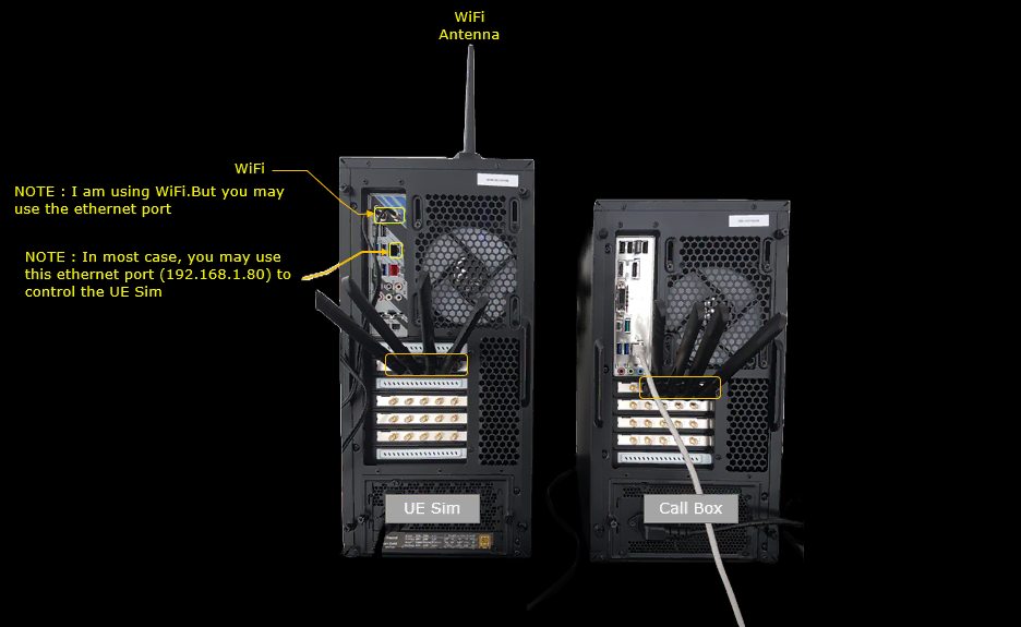
In this setup, two instances of MME is running in the callbox. MME 0 runs together with LTE service and MME 1 runs manually.
Configuration
There are so many configuration files applied to almost every component of the system. It may be confusing if you don't have clear understandings on overall test concept. Keep the illustration at the beginning of this page in mind and try to associate these configurations to the illustration.
Configuration File Setup
I used ue-lte-2plmn.cfg which is copied and modified from ue.default.cfg on UE sim.

I used enb-1cell-2plmn.cfg which is copied and modified from enb.default.cfg.

I used two separate mme configuration files : mme-ims-2plmn-0.cfg and mme-ims-2plmn-1.cfg which are copied and modified from mme-ims.cfg. Note that mme.cfg is symbolically linked to mme-ims-2plmn-0.cfg. ue_db-ims-2plmn.cfg is copied and modified from ue_db-ims.cfg. ue_db-ims-2plmn.cfg is called (included) within mme-ims-2plmn-0.cfg and mme-ims-2plmn-1.cfg
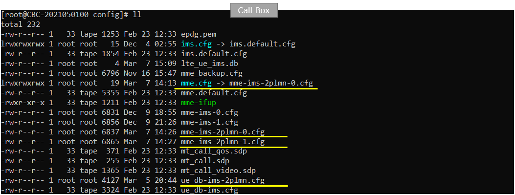
I used ots-2mme.cfg which is copied and modified from ots.default.cfg

Configuration for eNB
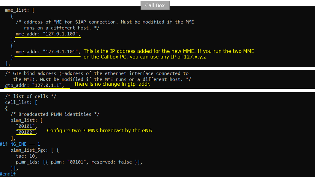
In enb-1cell-2plmn.cfg, I made modifications as follows. Note that one more mme_addr is added. 127.0.1.100 is mme_addr of MME 0 and 127.0.1.101 is mme_addr of MME 1.
Configuration for MME 0
Followings are the configuration in mme-ims-2plmn-0.cfg
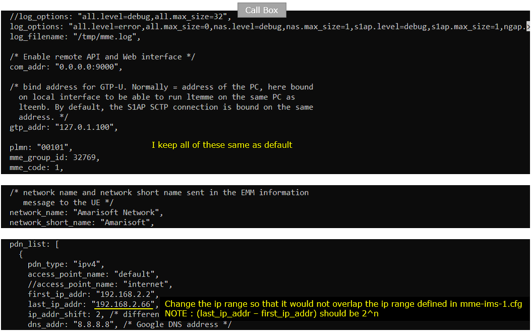
I keep the plmn as default (00101). The import configuration here is that adjusting IP range for each pdn_type so that it would not overlap with the other MME.
Set the first_ip_addr to 192.168.2.2 and the last_ip_addr to 192.168.2.66 for "default" PDN.(
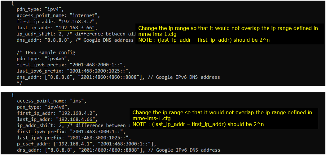
Set the first_ip_addr to 192.168.3.2 and the last_ip_addr to 192.168.3.66 for "internet" PDN.(NOTE : You need to set these IP so that last_ip_addr - first_ip_addr is 2^n). And changed ipv6 address in the same logic.
Set the first_ip_addr to 192.168.4.2 and the last_ip_addr to 192.168.4.66 for "ims" PDN.(NOTE : You need to set these IP so that last_ip_addr - first_ip_addr is 2^n). And changed ipv6 address in the same logic.
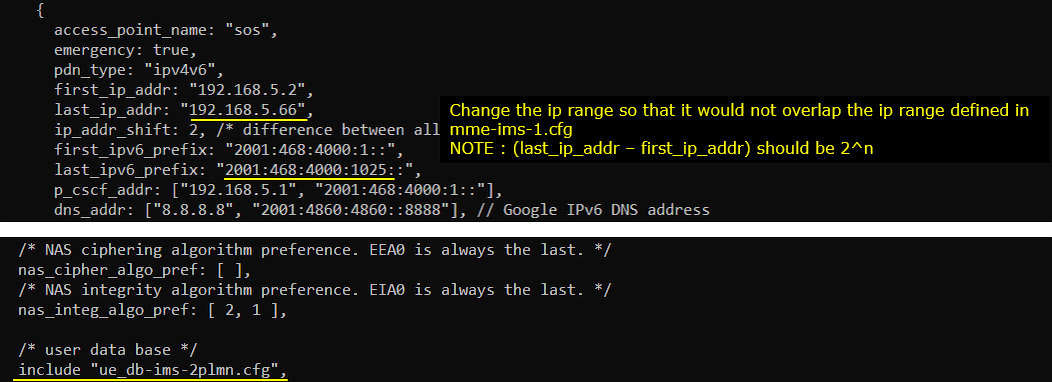
Set the first_ip_addr to 192.168.5.2 and the last_ip_addr to 192.168.5.66 for "sos" PDN.(NOTE : You need to set these IP so that last_ip_addr - first_ip_addr is 2^n). And changed ipv6 address in the same logic.
Configuration for MME 1
Followings are the configuration in mme-ims-2plmn-1.cfg . NOTE that this MME has configured for the PLMN 00101 and use the gtp_addr which is different from MME 0.
I changed the com_addr, gtp_addr, plmn in such a way that it does not overlap with MME 0 configuration.
Set the first_ip_addr to 192.168.2.100 and the last_ip_addr to 192.168.2.164 for "default" PDN.(
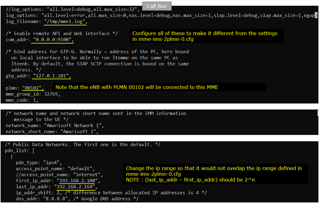
Set the first_ip_addr to 192.168.3.100 and the last_ip_addr to 192.168.3.164 for "internet" PDN.(NOTE: You need to set these IP so that last_ip_addr - first_ip_addr is 2^n). And change the ipv6 address in the same logic.
Set the first_ip_addr to 192.168.4.100 and the last_ip_addr to 192.168.4.164 for "ims" PDN.(NOTE: You need to set these IP so that last_ip_addr - first_ip_addr is 2^n). And change the ipv6 address in the same logic.
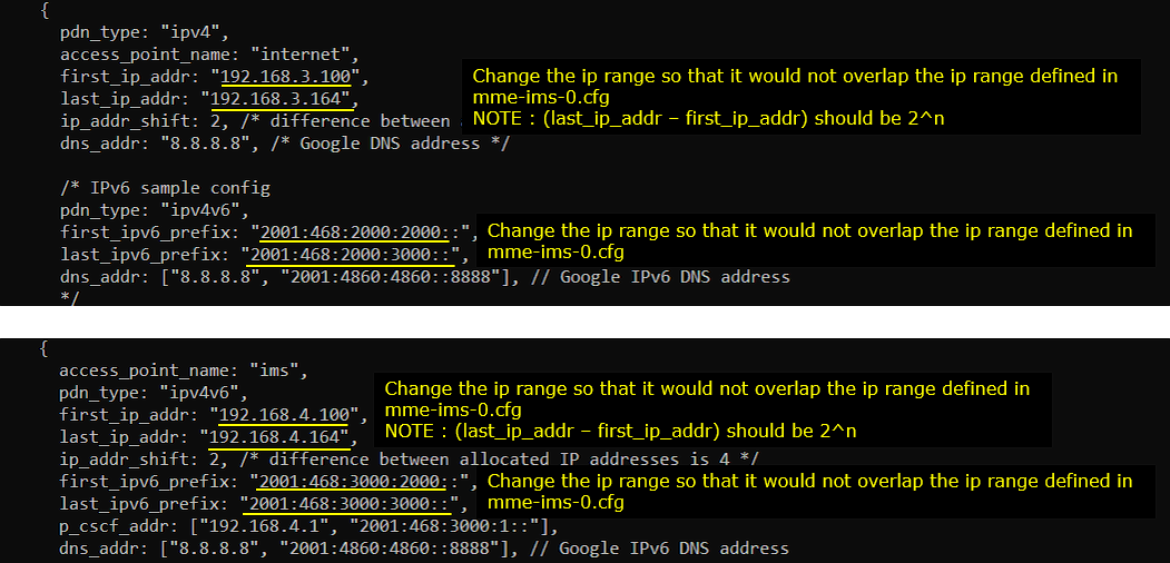
Set the first_ip_addr to 192.168.5.100 and the last_ip_addr to 192.168.5.164 for "sos" PDN.(NOTE: You need to set these IP so that last_ip_addr - first_ip_addr is 2^n). And change the ipv6 address in the same logic.
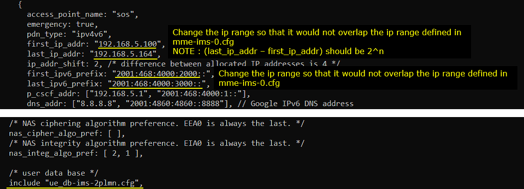
Configuration for ue_db
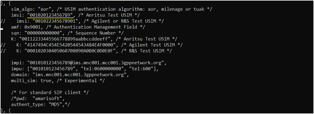
In ue_db-ims-2plmn.cfg, I have defined two USIM parameters as shown below. The first USIM parameter is one of the default parameters and the second one is just copy of the first one and I just changes PLMN.
For the first UE, I set the imsi to 0010123456789 with PLMN part 00101
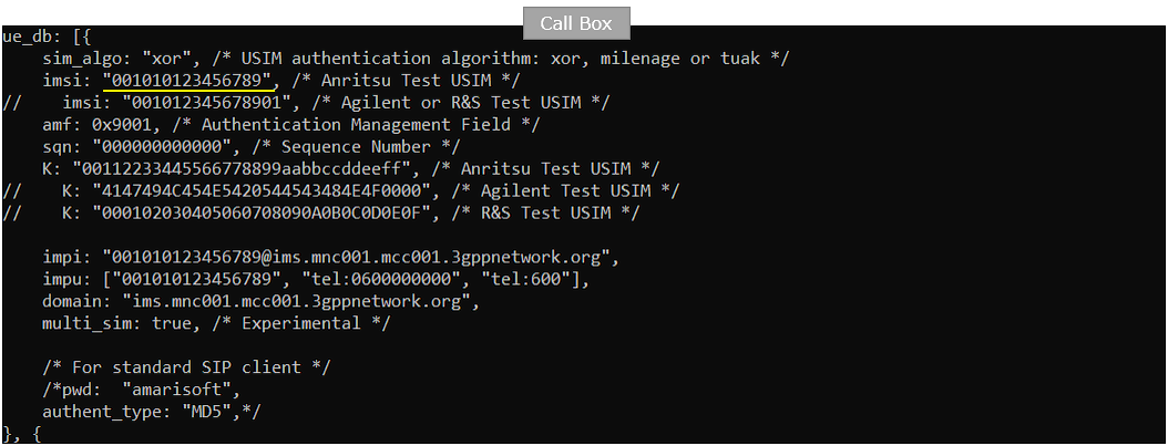
For the second UE, I set the imsi to 0010223456789 with PLMN part 00102
Configuration for ots
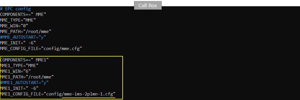
In ots-2mme.cfg , I have added the following part to lauch the second mme in addition to the first mme by lte service. I created a new component named "MME1" and associated it with mme-ims-2plmn-1.cfg.
Configuration for UEsim
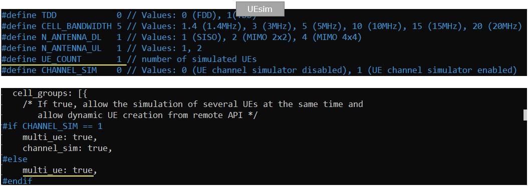
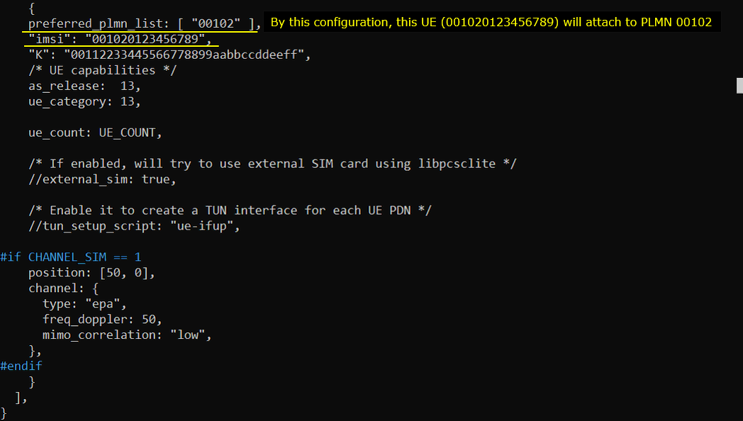
In ue-lte-2plmn.cfg , I have configured the following two UEs. What I want to try is to configure two UEs and let each of the UE to camp onto two different PLMN configured in Callbox.
First, it is important to set multi_ue: true since I want to simulate two UEs in this test.
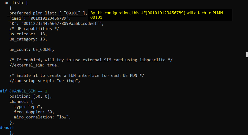
For the first UE, I forced it to camp onto the plmn "00101" by setting preferred_plmn_list to "00101" and setting ims to "001010123456789"
For the second UE, I forced it to camp onto the plmn "00102" by setting preferred_plmn_list to "00102" and setting ims to "001020123456789"
Perform the test
Check basic cell configuration with cell phy and cell command and see if it is configured as intended.

In (enb) check the status of s1 connection. It will take some time for both mme to launch. It will take around 30 secs until you get both s1 connected.

Start (enb) trace log

Power on the first UE in UEsim. If you are using commercial UE instead of UEsim, power on the first UE.
![]()
Confirm that the UE camp onto the cell.

Power on the second UE in UEsim. If you are using commercial UE instead of UEsim, power on the second UE.
![]()
Confirm that the UE camp onto the cell.

Check the connected UEs in (enb) and you will see the two UEs are listed. (NOTE : If the UE complete the attach and gets into idle mode, you would not see the UE in this list even if it camped on. Don't worry about it and proceed to next step)

Check on the connected UE in mme (MME 0) and confirm that the UE is assigned with an IP address. Also you can confirm on PLMN that the UE registered here.

Check on the connected UE in mme (MME 1) and confirm that the UE is assigned with an IP address. Also you can confirm on PLMN that the UE registered here.

Log Analysis
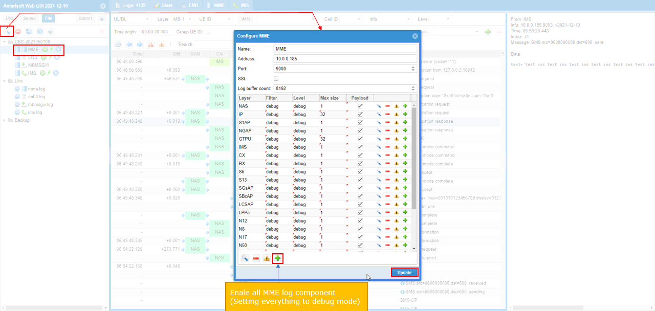
To verify the operation of MOCN, you need the log for almost all the components of RRC, NAS, Core Network. Enable ENB, MME. For ENB, you may only need RRC, NAS, but I would recommend you to collect the log for all the component of ENB, MME.
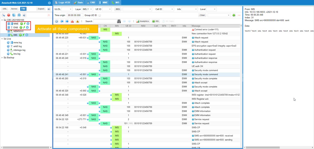
Enable all the components of MME (Corenetwork) log.
You may filter NAS, RRC, S1AP for Analysis for signaling message that are related to MOCN operation.
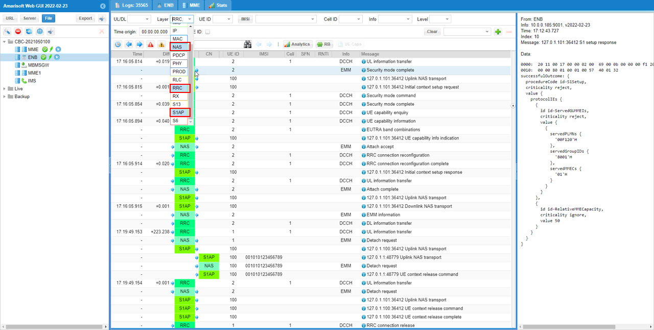
Make it sure that S1AP is established both for MME1 and MME2.
Check out SIB1 and ensure that it is broadcasting two PLMNs that are specified in the configuration file. In terms of signaling point of view, this is a crucial part of MOCN.
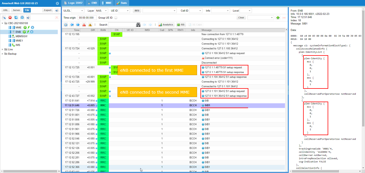
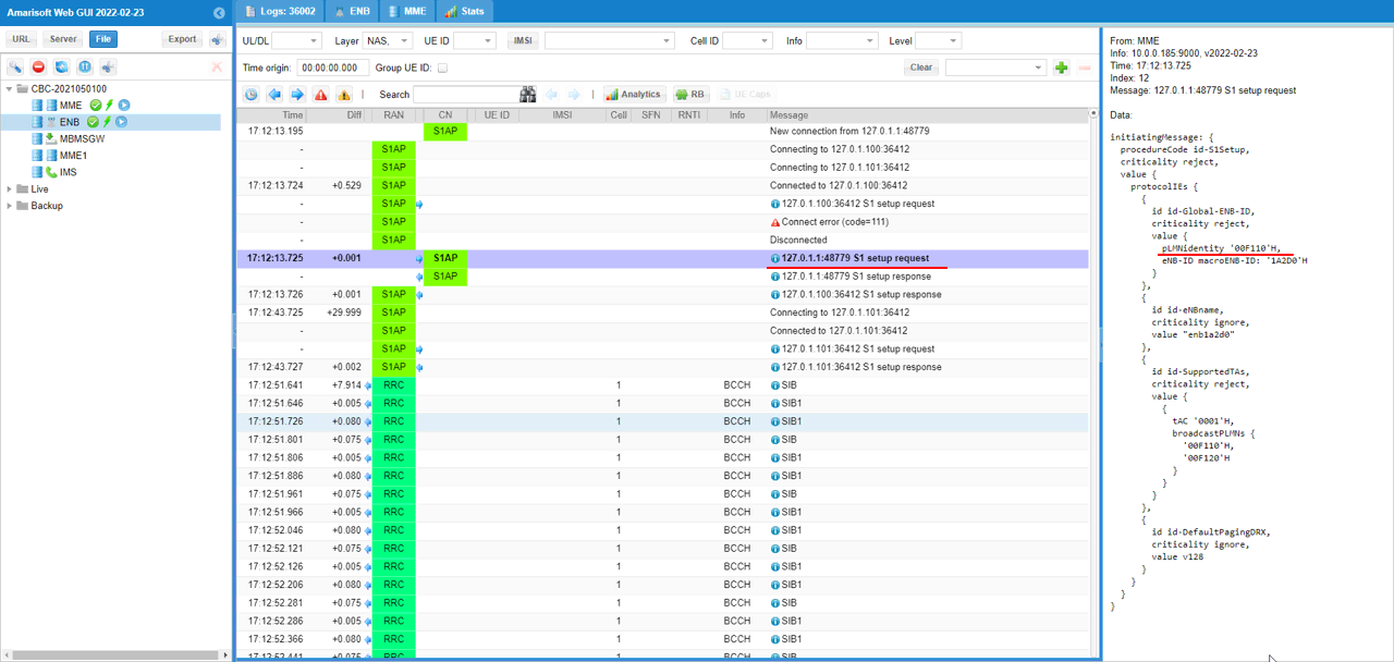
Check out S1AP setup to MME1 (you can confirm on this with IP and port number) and pLMNIdentity and broadcastPLMNs. You see here that pLMNIdentity is 00101 and broadcastPLMN is set to be 00101 and 00102.
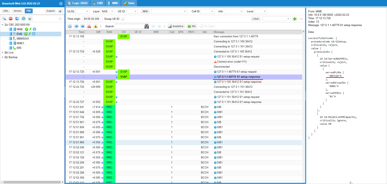
Check out S1AP setup response from MME1 and confirm servedPLMNs. It is set to 00101.
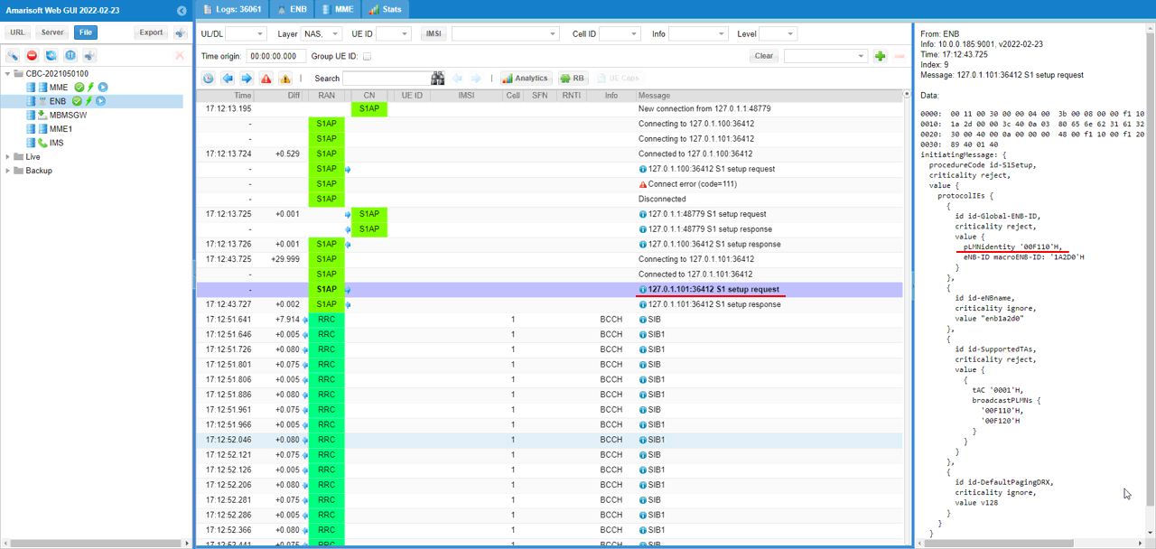
Check out S1AP setup to MME2 (you can confirm on this with IP and port number) and pLMNIdentity and broadcastPLMNs. You see here that pLMNIdentity is 00101 and broadcastPLMN is set to be 00101 and 00102.
Check out S1AP setup response from MME1 and confirm servedPLMNs. It is set to 00102.
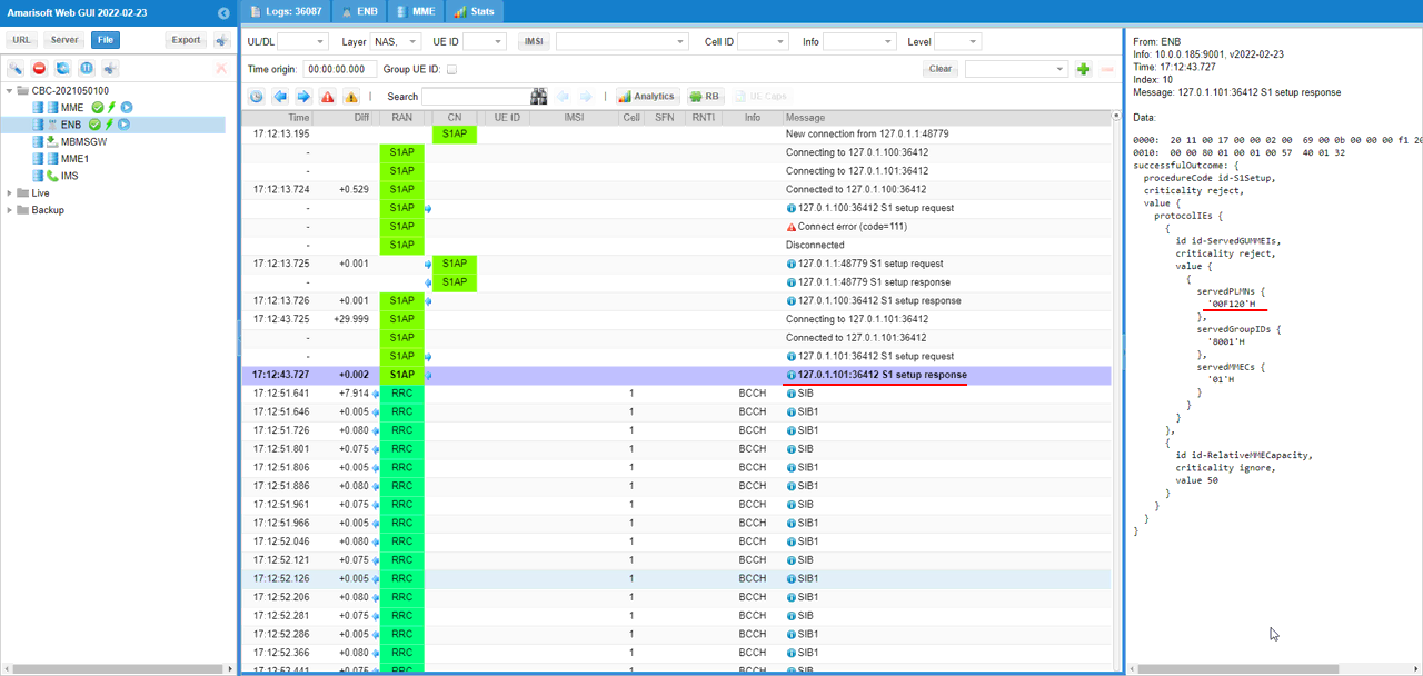
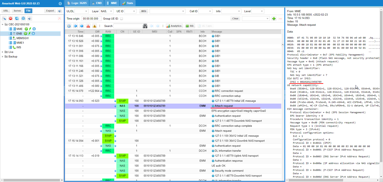
Check out Attach Request from the first UE(You can tell each UE apart from UE ID) and confirm on IMSI value. It is 0010123456789 in this case.
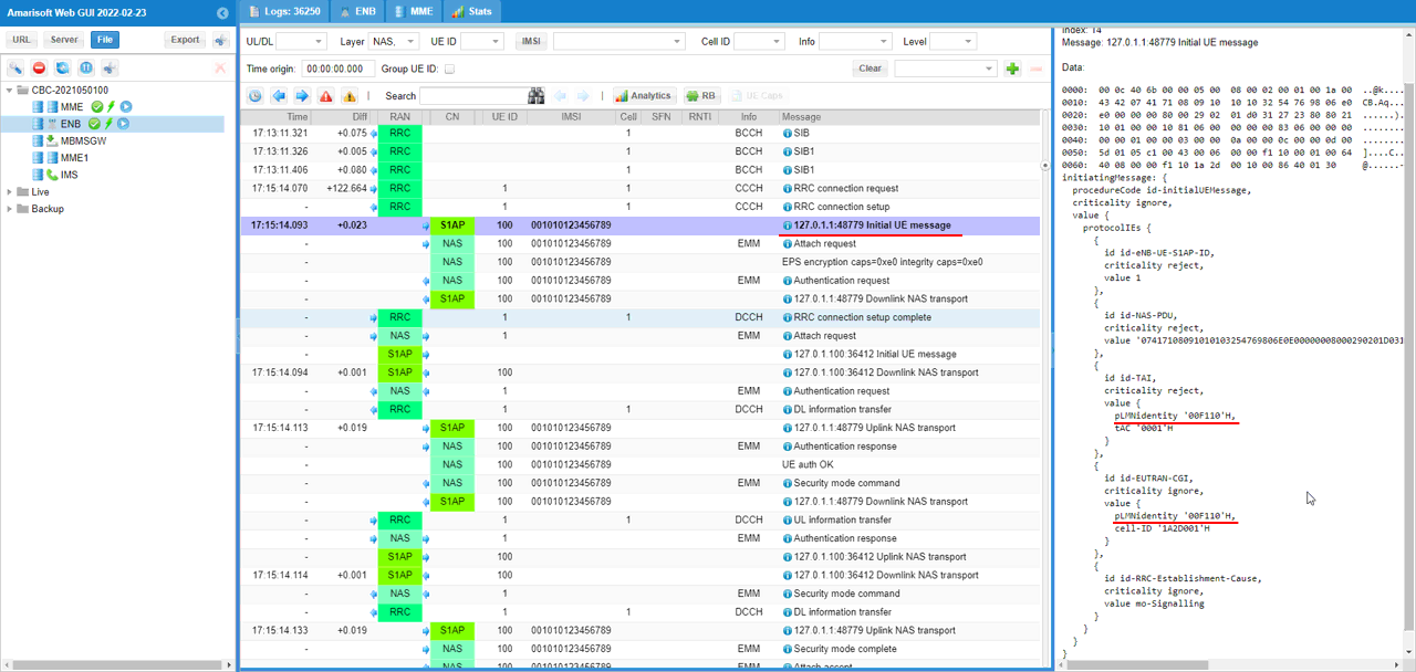
Check out S1AP Initial UE message for MME1 and confirm on id-TAI pLMNidentity and id-EUTRAN-CGI pLMNIdentity. Both are set to 00101 in this case.
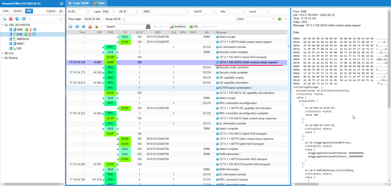
Check out S1AP Initial context setup request message for MME1
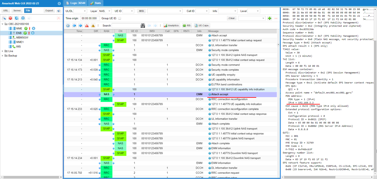
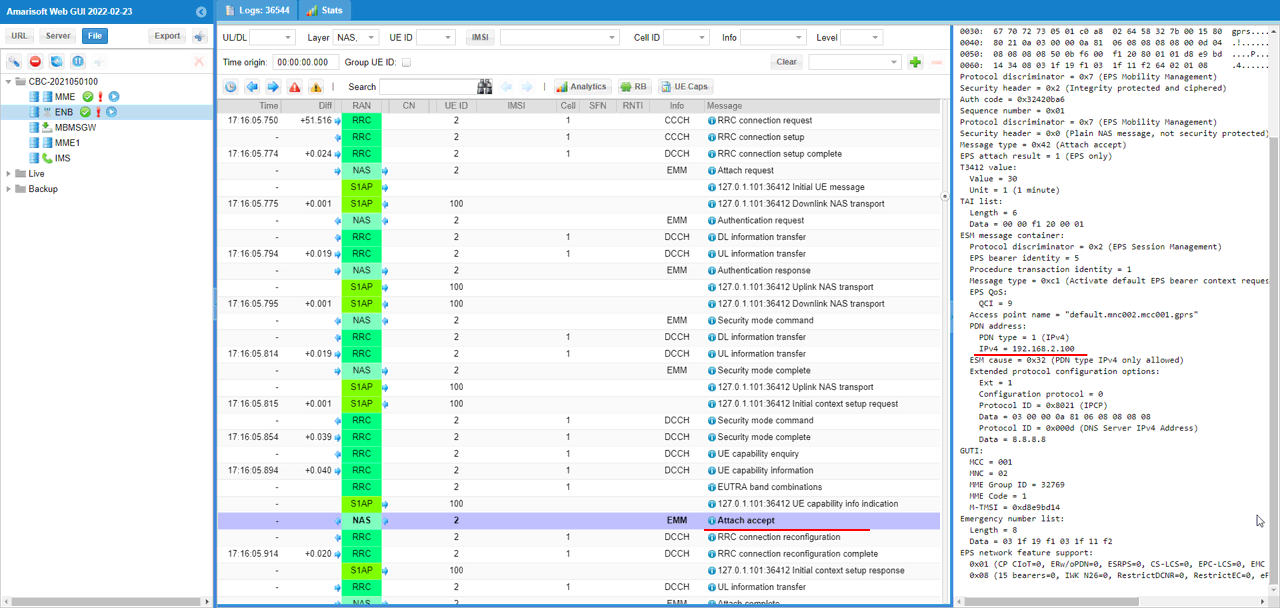
Check out Attatch Accept for UE1 and confirm that the assigned IP is within the range that you specified in the configuration file.
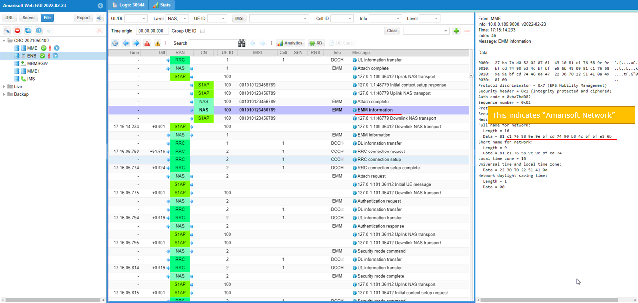
Check out ESM Information for UE1 and take a look at network name. It is set to "Amarisoft Network" in this case.
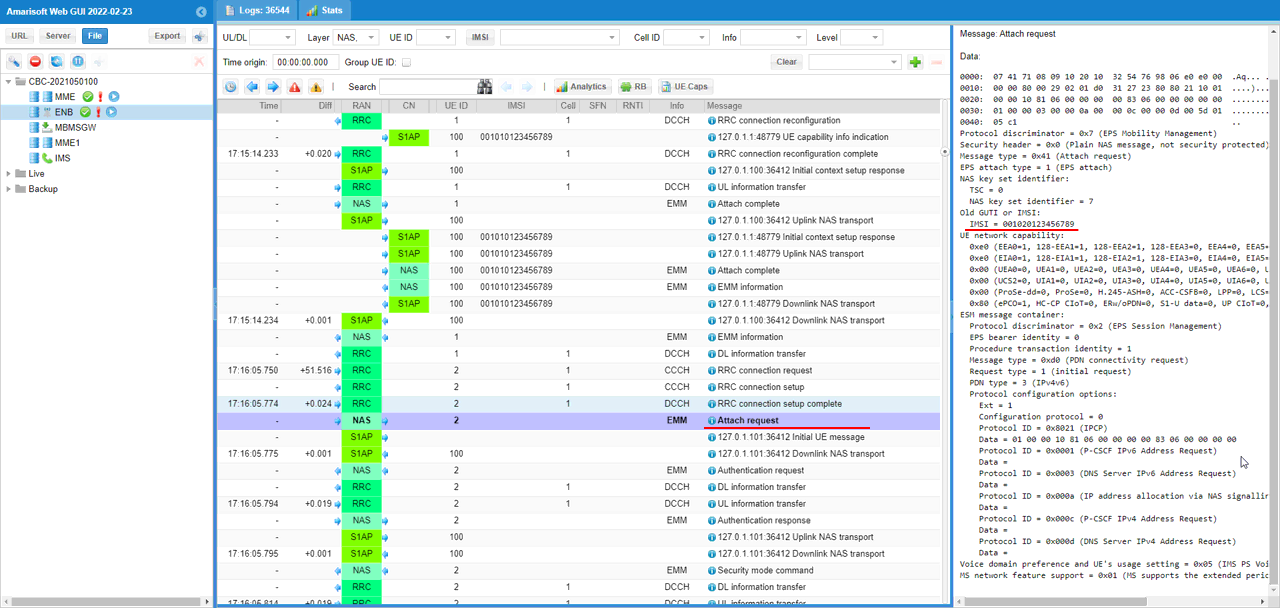
Check out Attach Request from the second UE(You can tell each UE apart from UE ID) and confirm on IMSI value. It is 0010223456789 in this case.
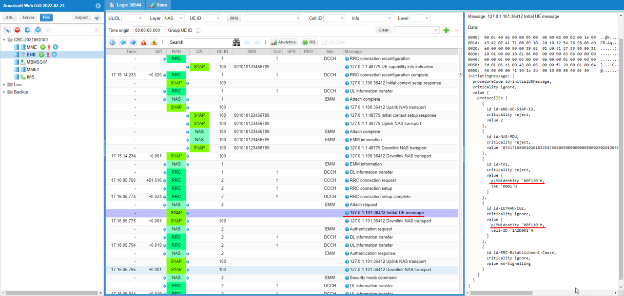
Check out S1AP Initial UE message for MME2 and confirm on id-TAI pLMNidentity and id-EUTRAN-CGI pLMNIdentity. id-TAI pLMNidentity are set to 00102 and id-EUTRAN-CGI pLMNIdentity is set to 00101 in this case.
Check out S1AP Initial context setup request message for MME1
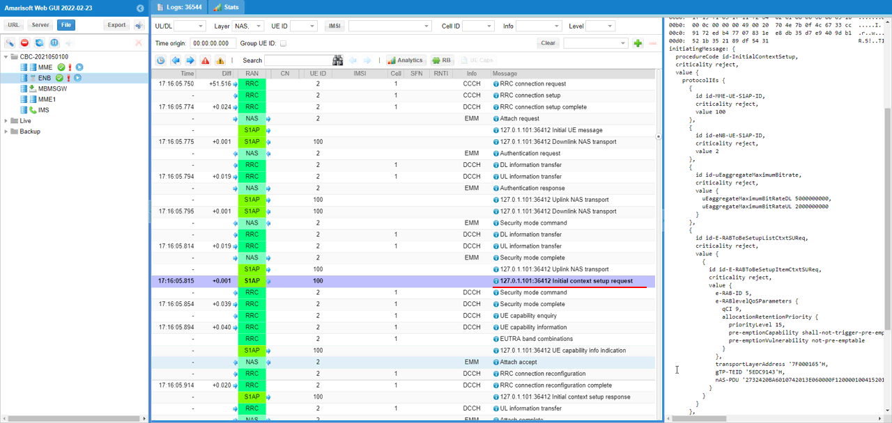
Check out Attatch Accept for UE2 and confirm that the assigned IP is within the range that you specified in the configuration file.
Check out ESM Information for UE1 and take a look at network name. It is set to "Amarisoft Network 1" in this case.
RRC / NAS Signaling
SIB1
: This is the SIBmessage sent by eNB to configure multiple PLMN. (
{
message c1: systemInformationBlockType1: {
cellAccessRelatedInfo {
plmn-IdentityList {
{
plmn-Identity {
mcc {
0,
0,
1
},
mnc {
0,
1
}
},
cellReservedForOperatorUse notReserved
},
{
plmn-Identity {
mcc {
0,
0,
1
},
mnc {
0,
2
}
},
cellReservedForOperatorUse notReserved
}
},
...
},
cellSelectionInfo {
...
},
...
schedulingInfoList {
...
},
...
}
}
EMM Information
: This is the EMM Information sent by eNB to inform the network name. (
Protocol discriminator = 0x7 (EPS Mobility Management)
Security header = 0x2 (Integrity protected and ciphered)
Auth code = 0xba7bd082
Sequence number = 0x02
Protocol discriminator = 0x7 (EPS Mobility Management)
Security header = 0x0 (Plain NAS message, not security protected)
Message type = 0x61 (EMM information)
Full name for network:
Length = 16
Data = 81 c1 76 58 9e 9e bf cd 74 90 b3 4c bf bf e5 6b
Short name for network:
Length = 9
Data = 81 c1 76 58 9e 9e bf cd 74
Local time zone = 10
Universal time and local time zone:
Data = 22 30 70 22 51 41 0a
Network daylight saving time:
Length = 1
Data = 00
Tips
Decoding Network Name
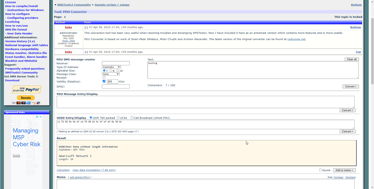
You can decode Network Name into human readable format using an online tool : http://smstools3.kekekasvi.com/topic.php?id=288
