LTE MDT
The purpose of this tutorial is to show how to configure and trigger MDT (Minimization of Driving Test). 'Drive Test' is a kind of testing in which you drive a testing vehicle around a certain route measuring various network performance (e.g, Cell Power, Interference) or UE performance (e.g, Call Drop, Throughput, Handover performance, Cell Reselection Performance etc). Usually during this period, you would collect a lot of protocol logs from UE and analyze by yourself or send them to developers when they have serious problems.
MDT is a feature introduced in 3GPP with the attempt to utilize normal UEs in the field to collect those information and report it to network which hopefully replace driving test as much as possible. According to 37.320, MDT has very wide spectrum as follows.
- Measurement Report from Network : Measurement that should be done by network (eNB) such as M3,4,5,6,7
- Measurement Report from UE : Measurement that should be done and reported to eNB such as M1,2,8,9
The MDT that Amarisoft support is Measurement Report from UE and this tutorial is also about this category.
Table of Contents
Introduction
Minimization of Drive Tests (MDT) is a significant feature standardized by the 3GPP to revolutionize the way mobile network performance data is collected and analyzed. Traditionally, assessing radio network quality and user experience relied heavily on extensive 'drive tests,' which involved deploying specialized vehicles equipped with measurement equipment to traverse target areas while capturing key performance indicators (KPIs) such as signal strength, interference levels, handover success rates, and call drop statistics. While effective, this approach is resource-intensive, costly, and limited in spatial and temporal coverage. MDT addresses these limitations by harnessing the ubiquity of commercial User Equipment (UE) in the field, enabling the network to remotely configure, trigger, and collect measurement reports from regular devices during normal operation. Architecturally, MDT operates through a collaborative mechanism between the UE, the radio access network (eNodeB or gNodeB), and the core network, leveraging control plane signaling to instruct UEs to perform specific measurements and report their results. MDT is further categorized into network-initiated measurements (performed by the base station) and UE-initiated measurements (performed and reported by the UE), with the latter being the focus of this tutorial and widely supported by platforms such as Amarisoft. By facilitating large-scale, real-time, and cost-effective monitoring of network performance, MDT plays a pivotal role in automated optimization, troubleshooting, and quality assurance within modern LTE and NR ecosystems. Its deployment reduces reliance on manual drive testing, contributes to continuous service improvement, and supports advanced features such as self-organizing networks (SON). Understanding how to configure and trigger MDT is essential for network engineers, testers, and operators seeking to leverage field data for proactive network management and enhanced user experience.
-
Context and Background
- Traditional drive tests involve manual data collection using instrumented vehicles, offering limited coverage and incurring high operational costs.
- MDT, as defined in 3GPP technical specifications (notably TS 37.320), enables regular UEs to automatically perform and report measurements during normal operation.
- MDT supports both network-initiated and UE-initiated measurement modes, broadening the spectrum of data and scenarios that can be analyzed.
- This tutorial focuses on UE-initiated MDT measurement reporting as supported by Amarisoft, which is widely applicable for real-world network optimization.
-
Relevance and Importance of MDT
- Eliminates or minimizes the need for costly and logistically complex drive tests, enabling continuous and scalable network monitoring.
- Provides richer, more granular data from a diverse set of UEs across different environments and mobility patterns.
- Supports proactive troubleshooting, network planning, and optimization efforts, ultimately enhancing end-user quality of experience (QoE).
- Aligns with the evolution towards automated, self-organizing, and data-driven mobile network management paradigms.
-
Learning Outcomes
- Understand the architectural principles and workflow of MDT in LTE/NR networks.
- Gain hands-on knowledge of configuring and activating MDT measurement tasks using Amarisoft or similar platforms.
- Learn how to analyze and interpret measurement reports collected via MDT for network performance evaluation and optimization.
- Develop the ability to leverage MDT for reducing operational costs and improving network diagnostics.
-
Prerequisite Knowledge and Skills
- Basic understanding of LTE/NR network architecture and protocol stack.
- Familiarity with radio resource management concepts and measurement procedures.
- Experience with network management systems or eNodeB/gNodeB configuration tools is beneficial.
- General knowledge of 3GPP standards and technical specification documents is helpful.
Summary of the Tutorial
This tutorial demonstrates the procedure for performing a Logged Measurement Report test (MDT - Minimization of Drive Tests) using Amarisoft Callbox and UEs. The focus is on configuring the environment, executing the test scenario, and analyzing the results to validate logged measurement reporting following a Radio Link Failure (RLF) event.
- Test Setup
- The test environment uses an Amarisoft Callbox (eNB) and UEs connected as shown in the provided diagram.
- Key Configuration Parameters
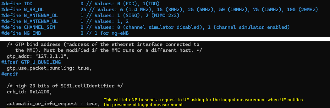
- Important system configuration parameters are highlighted, notably automatic_ue_info_request (enables the eNB to automatically request logged measurements upon notification from the UE).
- Remote API configuration via rrc_logged_meas_config is used to trigger and customize the measurement logging on the UEs.
- Test 1: Logged Measurement Report
- The test validates the basic operation of logged measurement reporting using the following steps:
- Step 1: Configure the Logged Measurement Report on the UE using the Remote API (rrc_logged_meas_config). This includes parameters such as ran_ue_id, trace_reference, logging_duration, and logging_interval.
- Step 2: Reduce the cell power level to intentionally induce a Radio Link Failure (RLF), causing the UE to lose connection and drop the call.
- Step 3: Restore cell power and allow the UE to reattach. During the attach process, the UE notifies the eNB that it has logged measurement data available.
- Step 4: The eNB automatically retrieves the logged measurement data from the UE via RRC signaling, leveraging the automatic_ue_info_request parameter set to true.
- Detailed Procedure
- Ensure that the UE is initially attached and in connected mode with the eNB.
- Trigger the logged measurement using the Remote API command, specifying relevant configuration attributes in the request.
- After triggering, decrease the cell power to cause the UE to lose radio connectivity (RLF event).
- Power cycle or reset the UE, then perform a standard network attach procedure.
- Upon reattachment, the UE signals the availability of logged measurement data.
- The eNB requests the logged measurement report from the UE, and the UE returns the report over the RRC interface.
- Log Analysis
- Analyze logs to verify:
- UE capability enquiry and confirmation of loggedMeasurementIdle support.
- Correct dispatch of the loggedMeasurementConfiguration from the eNB.
- Proper notification of logged measurement data by the UE after RLF and reattach.
- eNB's request and retrieval of the logged measurement information.
- Analyze logs to verify:
This tutorial provides a step-by-step methodology to configure, execute, and verify the logged measurement reporting process, focusing on configuration steps, test execution, and log verification while maintaining the necessary technical structure and format.
Test Setup
Test setup for this tutorial is as shown below.

Key Configuration Parameters
Followings are important configuration parameters for this tutorial. You may click on the items for the descriptions from Amarisoft documents.
- Configuration Parameter
- Remote API
Test 1 : Logged Measurement Report
In this test, I am going to show you the most basic method of operation for MDT. High level sequence of operation in this test is
- Step 1 : Configure LoggedMeasurement Report
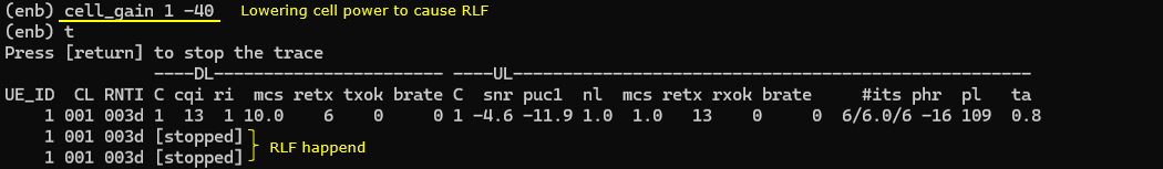
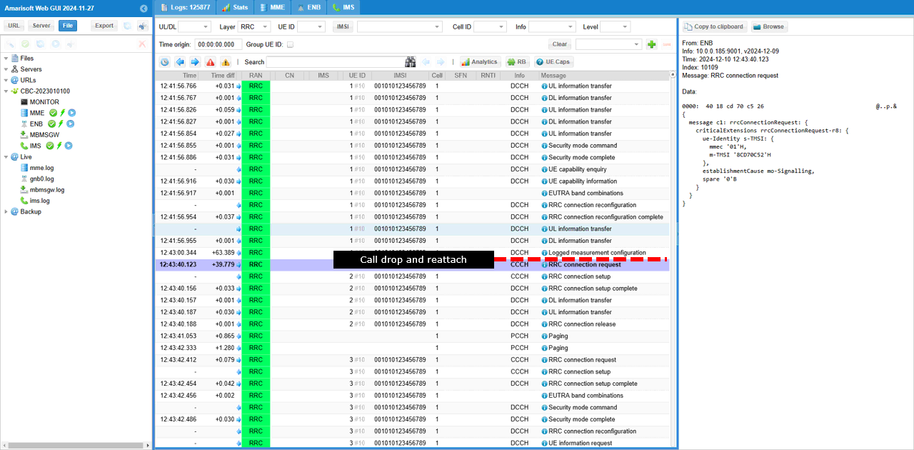
- Step 2 : Lower the cell power to cause RLF(Radio Link Failure) and Call drop
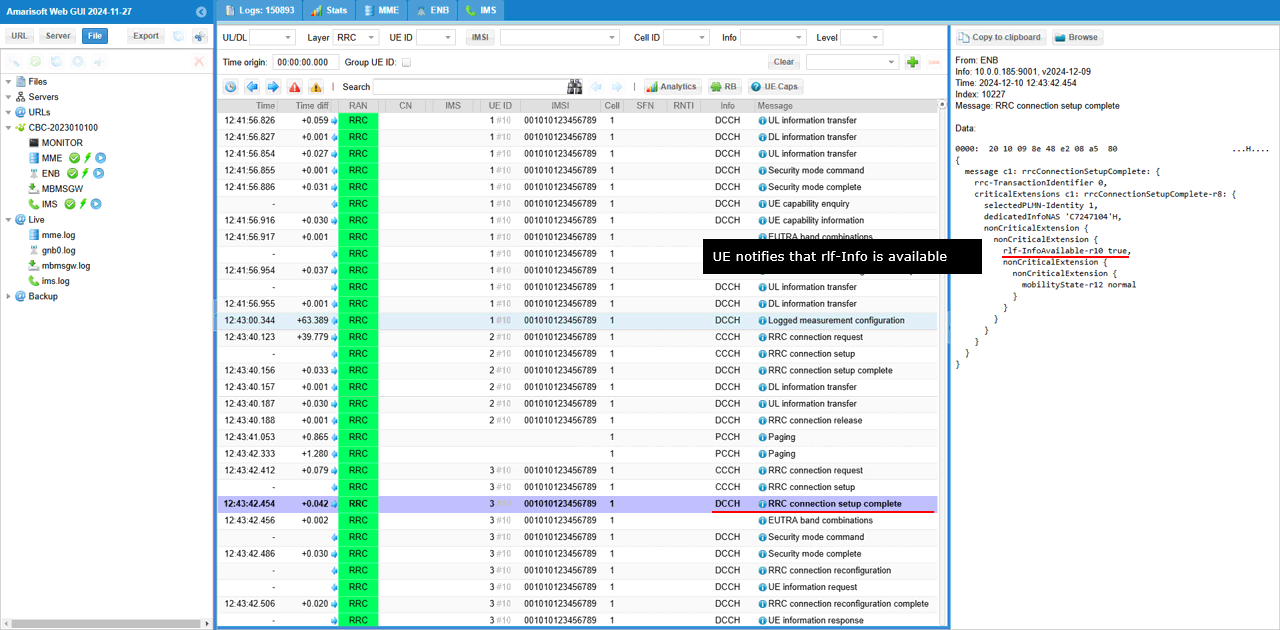
- Step 3 : Increase cell power and let UE attach to the cell. At this time of attach, UE notifies eNB that it has logged measurement
- Step 4 : eNB retrieves the logged measurement from UE via RRC message
Configuration
For Callbox (eNB) configuration, I used enb-mdt.cfg which is copied and modified from enb.default.cfg

In terms of configuration, it is super simple to enable tun setup for each UE. There is only one parameter to configure. It is automatic_ue_info_request. Setting this to true will let eNB to send a request to UE asking for the logged measurement when UE notifies to eNB the presence of the logged measurement result.
Perform the test
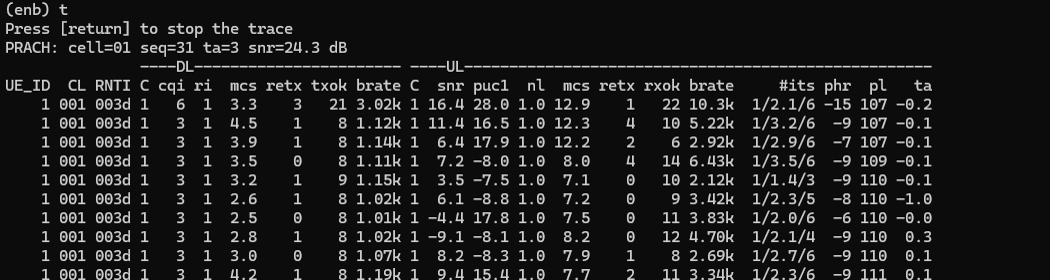
First make it sure that UE is in connected mode with eNB or gNB.
Power on UE and wait until the call gets connected.
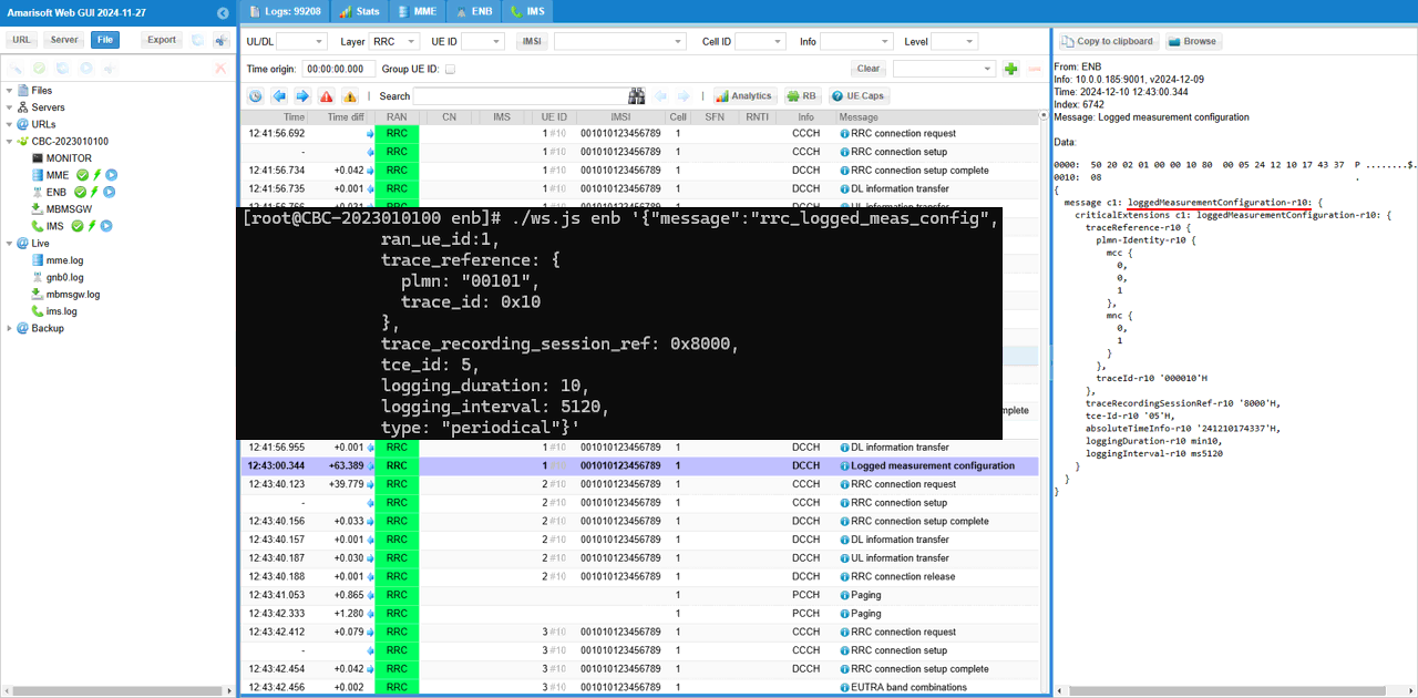
Then trigger the logged measurement using Remote API '{"message":"rrc_logged_meas_config", ...}
|
[root@CBC-2023010100 enb]# ./ws.js enb '{"message":"rrc_logged_meas_config", ran_ue_id:1, trace_reference: { plmn: "00101", trace_id: 0x10 }, trace_recording_session_ref: 0x8000, tce_id: 5, logging_duration: 10, logging_interval: 5120, type: "periodical"}' WebSocket remote API tool version 2024-12-09, Copyright (C) 2012-2024 Amarisoft [0.003] ### Connected to 127.0.0.1:9001 [0.003] ### Ready: name=ENB, type=ENB, version=2024-12-09 [0.022] <== Send message rrc_logged_meas_config id#1 [0.033] ==> Message received { "message": "rrc_logged_meas_config", "message_id": "id#1", "time": 2235.031, "utc": 1733842472.612 } |
Now reduce the cell power to the point where UE start loosing connection and generate RLF (Radio Link Failure).
Then power cycle UE and perform the normal attach and establish connection.
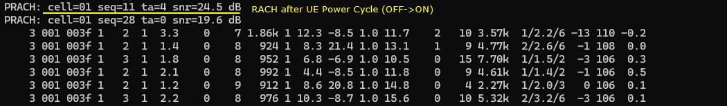
Log Analysis
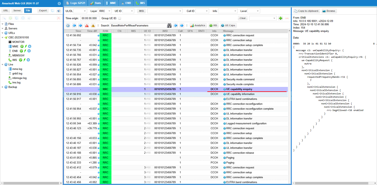
eNB sends UE capability enquiry.
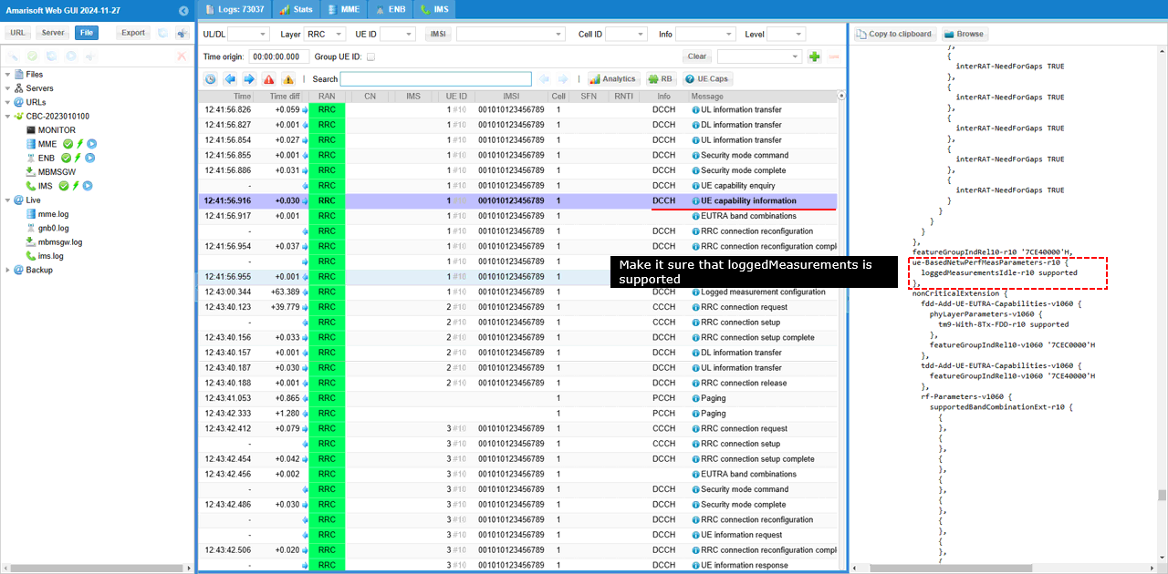
Check if UE support loggedMeasurementIdle capability.
Once you run RemoteAPI "rrc_logged_meas_config", eNB send loggedMeasurementConfiguration message.
Decrease Cell Power to cause RLF (RadioLink Failure) and power cycle UE to reattach.
UE should notify the presence of the logged measurement (rlf-InfoAvailable in this case) in RRC Connection Setup Complete message.
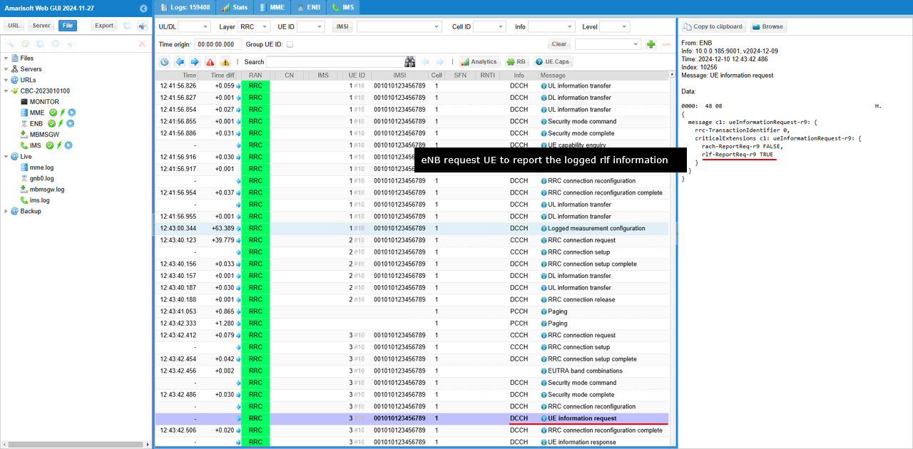
As a response to rlf-InfoAvailable in RRC Connection Setup Complete message, eNB send out ueInformationRequest message to retrieve the RLF information (rlf-ReportRes)
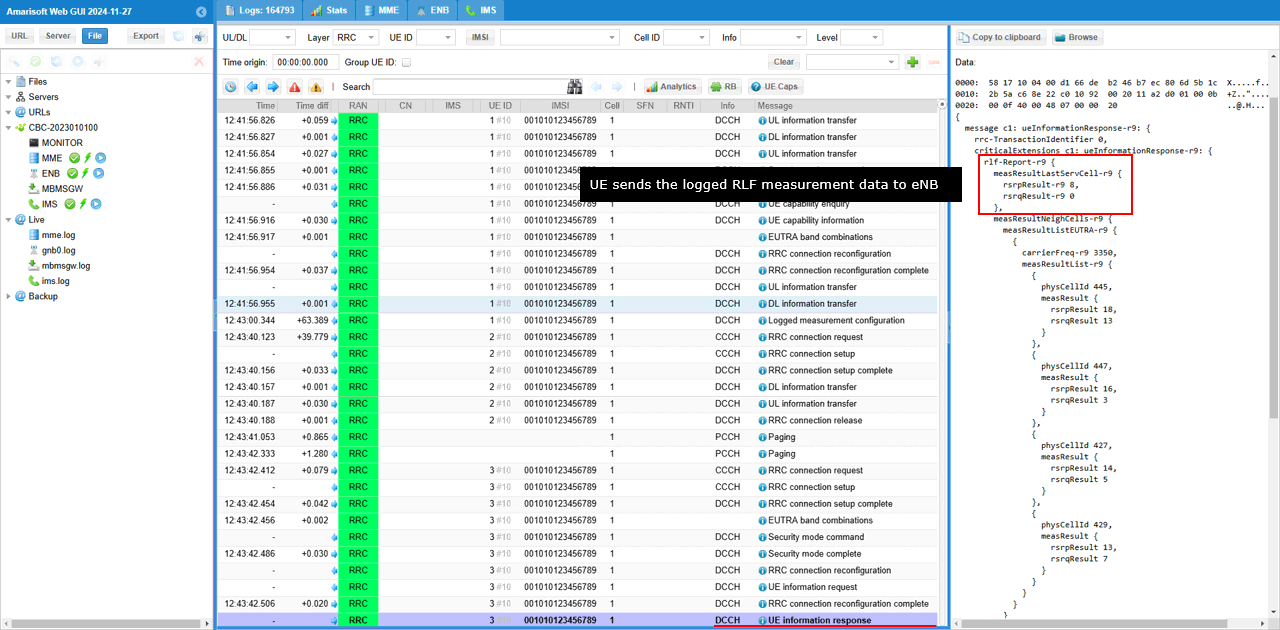
Then UE sends the logged measurement data (rlf-Report in this case) to eNB.
RRC / NAS Signaling
loggedMeasurementConfiguration
{
message c1: loggedMeasurementConfiguration-r10: {
criticalExtensions c1: loggedMeasurementConfiguration-r10: {
traceReference-r10 {
plmn-Identity-r10 {
mcc {
0,
0,
1
},
mnc {
0,
1
}
},
traceId-r10 '000010'H
},
traceRecordingSessionRef-r10 '8000'H,
tce-Id-r10 '05'H,
absoluteTimeInfo-r10 '241210174337'H,
loggingDuration-r10 min10,
loggingInterval-r10 ms5120
}
}
}
ueInformationRequest
{
message c1: ueInformationRequest-r9: {
rrc-TransactionIdentifier 0,
criticalExtensions c1: ueInformationRequest-r9: {
rach-ReportReq-r9 FALSE,
rlf-ReportReq-r9 TRUE
}
}
}
ueInformationRequest
{
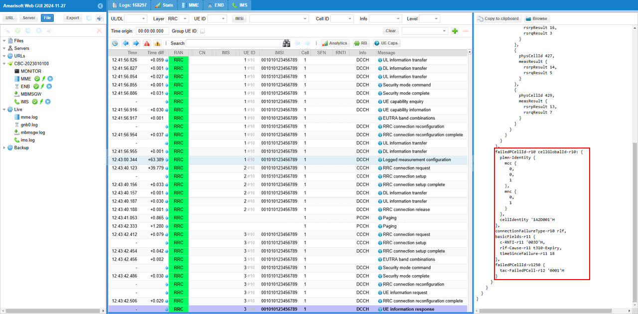
message c1: ueInformationResponse-r9: {
rrc-TransactionIdentifier 0,
criticalExtensions c1: ueInformationResponse-r9: {
rlf-Report-r9 {
measResultLastServCell-r9 {
rsrpResult-r9 8,
rsrqResult-r9 0
},
measResultNeighCells-r9 {
measResultListEUTRA-r9 {
{
carrierFreq-r9 3350,
measResultList-r9 {
{
physCellId 445,
measResult {
rsrpResult 18,
rsrqResult 13
}
},
{
physCellId 447,
measResult {
rsrpResult 16,
rsrqResult 3
}
},
{
physCellId 427,
measResult {
rsrpResult 14,
rsrqResult 5
}
},
{
physCellId 429,
measResult {
rsrpResult 13,
rsrqResult 7
}
}
}
}
}
},
failedPCellId-r10 cellGlobalId-r10: {
plmn-Identity {
mcc {
0,
0,
1
},
mnc {
0,
1
}
},
cellIdentity '1A2D001'H
},
connectionFailureType-r10 rlf,
basicFields-r11 {
c-RNTI-r11 '003D'H,
rlf-Cause-r11 t310-Expiry,
timeSinceFailure-r11 18
},
failedPCellId-v1250 {
tac-FailedPCell-r12 '0001'H
}
}
}
}
}