
LTE Cell Reselection
This tutorial shows how to test Cell Reselection on Amari Callbox and a commercial UE. Cell Reselection is a mechanism where UE can change the cell in Idle mode. The idle mode cell change happens in several different situations as listed below. When we say 'Cell Reselection', it usually mean the first two cases, but people say in a little different way depending on context.
- UE changes cell to another cell which has higher cell power with the same PLMN as the current cell.
- UE changes cell to another cell which has higher priorities. This priorities may be configured in SIB or RRC Release message.
- UE lost signal from the current cell and change to another cell with selectable cell. Strictly speaking this is more like a cell selection, but it can be considered as a type of reselection.
- UE first attached to a visiting PLMN and changes to another cell with Home PLMN. Strictly speaking this is called Roaming.
- UE attached to a cell and Network (eNB) explcitely direct UE to change to another cell via RRCConnectionRelease message. This is called Cell Redirection.
Table of Contents
Introduction
Cell Reselection is a critical procedure in mobile wireless communication systems that governs how a User Equipment (UE), such as a commercial smartphone or modem, autonomously selects and transitions between different radio cells while in idle mode. This mechanism ensures that the UE maintains optimal connectivity by dynamically evaluating available cells based on signal strength (cell power), broadcasted cell priorities, and network configurations specified in system information blocks (SIB) or Radio Resource Control (RRC) messages. Unlike active mode handover, which is network-directed, cell reselection is primarily UE-driven and operates without explicit signaling messages from the network. The mechanism is integral to scenarios such as improved signal reception, network load balancing, and seamless mobility, particularly in environments with multiple overlapping cells and varying levels of radio resources. The Amari Callbox serves as a highly flexible testing platform that emulates network conditions, allowing detailed observation and manipulation of the reselection process in conjunction with a commercial UE. Understanding and testing cell reselection is vital for ensuring robust device behavior, optimizing network performance, and diagnosing issues that may arise from suboptimal reselection events. This tutorial provides an in-depth, practical approach to evaluating cell reselection behavior using the Amari Callbox, highlighting key technical aspects, typical scenarios, and best practices for protocol analysis.
-
Context and Background
- Cell Reselection is a fundamental operation in 3GPP-compliant radio access networks (e.g., LTE, NR), allowing UEs to switch to a more suitable cell based on criteria such as received signal quality, cell priorities, and operator configuration.
- The Amari Callbox is a network emulator that provides precise control over radio conditions, cell parameters, and signaling, making it ideal for protocol testing and validation of UE idle mode procedures.
- In idle mode, the UE continuously monitors its serving cell and neighboring cells, applying reselection algorithms defined by the network’s configuration to maintain optimal service availability.
-
Relevance and Importance of the Tutorial Topic
- Testing cell reselection is crucial for validating UE compliance with 3GPP standards, optimizing mobility performance, and ensuring consistent user experience across diverse radio environments.
- It helps identify and troubleshoot issues related to idle mode mobility, such as delayed reselection, service loss, or unintended behavior, which can significantly impact network reliability and device usability.
- The insights gained from systematic reselection testing support both device manufacturers and network operators in refining mobility parameters and improving network configuration.
-
Learner Outcomes
- Gain hands-on experience with configuring and operating the Amari Callbox for advanced mobility testing.
- Develop a deep understanding of the technical criteria and signaling involved in the cell reselection process.
- Learn to interpret UE side logs and extract meaningful information related to idle mode procedures, such as cell search, neighbor detection, and reselection triggers.
- Acquire troubleshooting skills to diagnose and resolve typical cell reselection issues in commercial UEs.
-
Prerequisite Knowledge and Skills
- Basic understanding of mobile communications concepts, including LTE/NR radio access architecture and idle mode operations.
- Familiarity with the use of test equipment such as network emulators and protocol analyzers.
- Experience with interpreting UE logs and knowledge of 3GPP protocol specifications (especially RRC and SIB signaling) will be advantageous.
Summary of the Tutorial
This tutorial demonstrates two LTE cell reselection test procedures: Intra-Frequency Cell Power Based Reselection and Inter-Frequency Priority Based Reselection. The procedures involve step-by-step configuration, execution, and log analysis to validate the reselection mechanisms between two LTE cells using Amarisoft tools.
-
Test 1: LTE to LTE Reselection, Intra Frequency, Cell Power Based Reselection
-
Configuration Steps:
- Use enb-2cell-selection.cfg configuration file (set N_CELL to 2).
- Map cell id 1 to rf_port 0 with cell id 2 as neighbor; map cell id 2 to rf_port 1 with cell id 1 as neighbor.
- Ensure both cells use the same dl_earfcn (intra-frequency condition).
- Adjust q_rx_lev_min in cell_default to facilitate easier reselection.
-
Test Execution Steps:
- Start LTE service and verify that bands, frequencies, and dl_arfcn for both cells are identical.
- Check current tx_gain and rx_gain settings for both cells.
- Set cell power so the UE initially camps on cell 1 (lower cell 2 gain).
- Power on UE and confirm attachment to cell 1.
- Incrementally increase cell 2 power while decreasing cell 1 power to trigger reselection.
-
Log Analysis:
- Check q-RxLevMin value in cellSelectionInfo IE in SIB1 for both cells to verify initial attach conditions.
- Verify cellReselectionInformation in SIB3 for both cells (requires editing sib2_3.asn for custom values).
- Observe UE reselection by monitoring logs for UE camping transition from cell 1 to cell 2 after power adjustment.
-
Configuration Steps:
-
Test 2: LTE to LTE Reselection, Inter Frequency, Priority Based Reselection
-
Configuration Steps:
- Use enb-2cell-resel-priority.cfg configuration file.
- Create and apply new ASN.1 files: lte_resel_priority.asn (defines carrier frequencies and priorities), sib_2_3_5.asn (for SIB5), based on sib2_3.asn.
- Assign different frequencies to each cell for inter-frequency condition.
- Set different tac (Tracking Area Code) for each cell to ensure UE performs tracking area updates after reselection, aiding verification.
- Configure idle_mode_mobility_control parameter with the ASN file specifying frequency and priority.
- Add SIB5 to the broadcast SIB list to include inter-frequency reselection criteria.
- Remove measurement control settings to prevent eNB-triggered handover.
-
Test Execution Steps:
- Verify physical configuration of both cells to ensure correct frequency and settings.
- Set cell gains so UE initially camps on cell 1.
- Power on UE and confirm camping on cell 1.
- Observe UE reattaching to cell 2, verifying through logs that reselection was triggered by priority and not other causes.
-
Log Analysis:
- Confirm that SIB5 is broadcast and correctly configured.
- Analyze logs for RRC Connection Release message, confirming that reselection priorities are set and cell switching occurs according to configuration.
-
Configuration Steps:
Additional Reference:
The tutorial also provides an example of the RrcConnectionRelease message, highlighting the structure used to configure reselection priorities via the idleModeMobilityControlInfo field, which includes freqPriorityListEUTRA with specific carrierFreq and cellReselectionPriority entries.
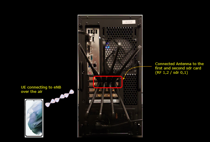
Test Setup
Test setup for this tutorial is as shown below.
- SIM Card used in this tutorial is the one delivered with the system as it is.
- If you want to change the configuration, The tutorial Configuration Guide would help
Key Configuration Parameters
Followings are important configuration parameters for this tutorial. You may click on the items for the descriptions from Amarisoft documents.
- idle_mode_mobility_control : In this link, you would get the descriptions for all the items listed below
- info
- info_v9e0
- sib_sched_list : In this link, you would get the descriptions for all the items listed below
- filename
- si_periodicity
- intra_freq_reselection
- q_rx_lev_min
Test 1 : LTE to LTE Reselection, Intra Frequency, Cell Power Based Reselection
In this test, I will show you how to configure and validate the cell reselection between two LTE cells with the same frequency (Intra Frequency) based on cell power.
Configuration
I used the enb-2cell-selection.cfg which was copied and modified from enc-2cell-ho.cfg . (NOTE : You can use the same file for both cell power based cell selection and cell reselection)
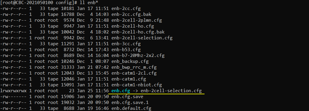
Now you would configure enb-2cell-selection.cfg as follows. N_CELL is set to 2 and you should not change this parameter.
This part defines the basic setup for the two-cell LTE reselection test. The most important setting is N_CELL, which is set to 2. This means the eNB runs two LTE cells for this test. This value is used by config.cfg, so it should not be changed.
TDD is set to 0, so this test uses FDD operation. N_RB_DL is set to 25, which means the LTE downlink bandwidth is 5 MHz.
Both N_ANTENNA_DL and N_ANTENNA_UL are set to 1. So the test uses a simple SISO configuration for both downlink and uplink. This keeps the radio setup simple because the main focus is idle mode cell reselection, not MIMO behavior.
CHANNEL_SIM is set to 0, so the channel simulator is disabled. Because of this, the reselection result is mainly controlled by the configured cell power and reselection parameters.
NG_ENB is set to 0, meaning this is a normal LTE eNB configuration, not an ng-eNB configuration.

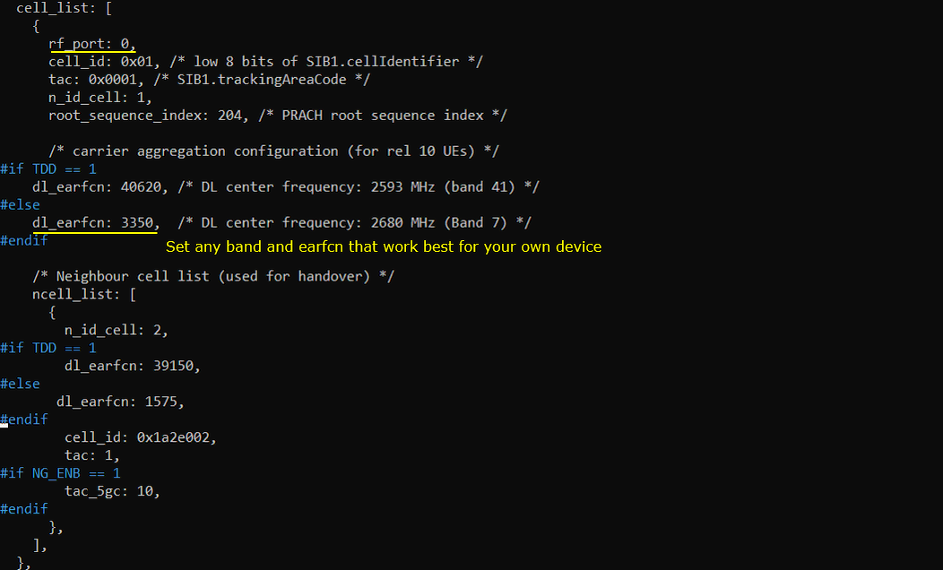
Following is the cell mapped to rf_port 0. As you see here, cell id 1 is mapped to this port and cell_id 2 is configured as a neighbor cell.
This part maps the first LTE cell to RF port 0 and defines the second LTE cell as a neighbor cell.
The first important point is rf_port: 0. This means cell_id 1 is transmitted through RF port 0. In this test, this is the serving cell that the UE will initially detect and camp on.
cell_id is set to 0x01. This is the physical cell identity related value used for this LTE cell. tac is set to 0x0001, meaning this cell belongs to tracking area code 1. n_id_cell is set to 1, so this cell uses PCI 1. root_sequence_index is set to 204, which is used for PRACH preamble generation.
dl_earfcn is set to 3350 for FDD. This corresponds to LTE Band 7 with a downlink center frequency of 2680 MHz. The highlighted comment indicates that you can change the band and EARFCN depending on what works best for your own UE. This is important because not every UE supports every LTE band, and some UEs may behave differently depending on supported bands and regional configuration.
The neighbor cell list is defined under ncell_list. This list tells the UE that another LTE cell exists and can be used as a neighbor cell for mobility procedures such as handover or reselection.
Inside ncell_list, n_id_cell is set to 2. This means the neighbor cell uses PCI 2. For FDD, dl_earfcn is set to 1575. This defines the downlink frequency of the neighbor cell. cell_id is set to 0x1a2e002, and tac is set to 1, meaning the neighbor cell also belongs to tracking area 1.
In this specific configuration, cell 1 is the main cell configured on RF port 0, and cell 2 is advertised as a neighbor cell. The UE first camps on cell 1, but it can later evaluate cell 2 as a reselection candidate depending on the SIB information, frequency priority, reselection thresholds, and measured signal quality.
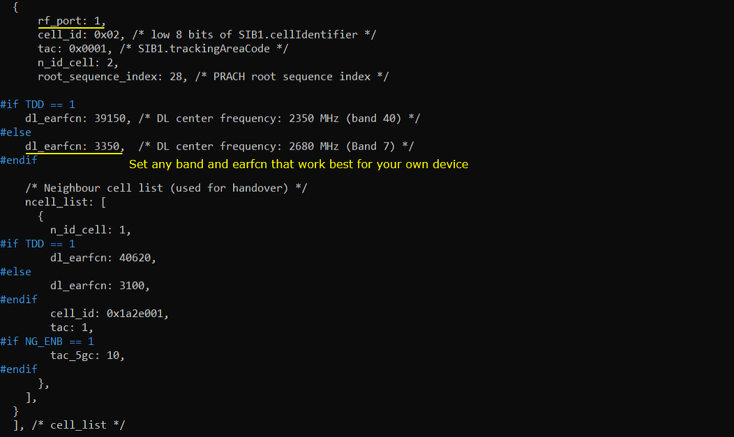
Following is the cell mapped to rf_port 1. As you see here, cell id 2 is mapped to this port and cell_id 1 is configured as a neighbor cell. Since this test is for intra cell reselection, set dl_earfcn of the second cell to be same as the first cell.
This part maps the second LTE cell to RF port 1 and defines the first LTE cell as its neighbor cell.
Here, rf_port is set to 1. This means cell 2 is transmitted through RF port 1. In this two-cell test, each cell uses a different RF port, so the signal power of each cell can be controlled separately.
cell_id is set to 0x02. This is the cell identifier value broadcast by the second cell. tac is set to 0x0001, so this cell belongs to the same tracking area as the first cell. n_id_cell is set to 2, meaning this cell uses PCI 2. root_sequence_index is set to 28, which is used for PRACH preamble generation for this cell.
For FDD, dl_earfcn is set to 3350. This is the same EARFCN as the first cell. This is an important point for this test. Since this test is for intra-frequency cell reselection, both cells should use the same downlink EARFCN. The UE does not need to move to another frequency. It only compares cells on the same carrier frequency.
The highlighted comment says to set any band and EARFCN that work best for your own device. This means you may change the EARFCN depending on the LTE bands supported by your UE. However, for this intra-frequency reselection test, the EARFCN of cell 1 and cell 2 should remain the same.
The neighbor cell list is defined under ncell_list. In this cell configuration, n_id_cell is set to 1. This means cell 1 is configured as the neighbor cell of cell 2. For FDD, the neighbor dl_earfcn is also configured for the corresponding LTE frequency. cell_id is set to 0x1a2e001, and tac is set to 1.
So the relationship is symmetric. In the previous part, cell 1 had cell 2 as its neighbor. In this part, cell 2 has cell 1 as its neighbor. This allows the UE to evaluate reselection in both directions, depending on which cell it is currently camped on and which cell becomes stronger.
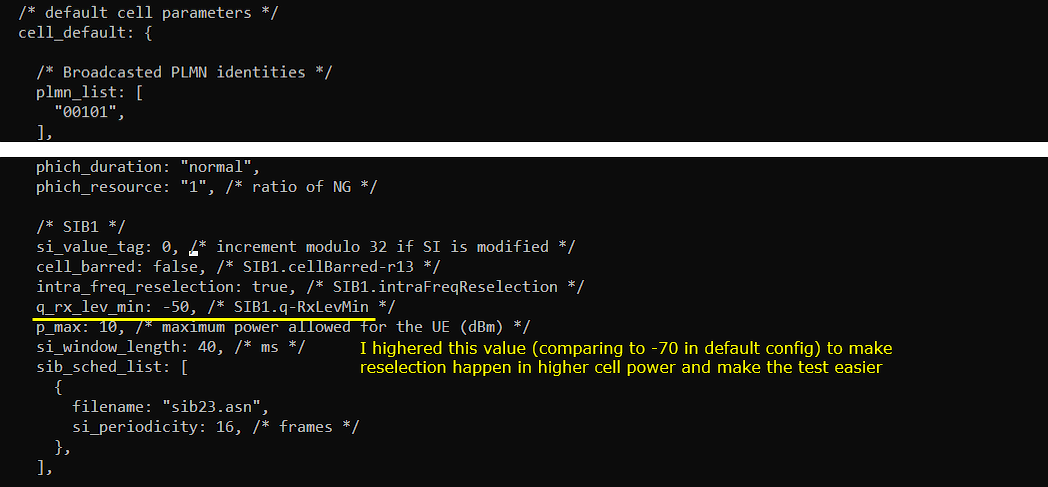
In cell_default: { } configuration, I increased the q_rx_lev_min just to make the test easier.
In cell_default configuration, I increased q_rx_lev_min to make the reselection test easier.
This part defines common default parameters applied to the LTE cells. Since these parameters are placed under cell_default, they are shared by the cells unless each cell overrides them separately.
plmn_list is set to 00101. This is the PLMN broadcast by the cell. The UE uses this information when checking whether the cell belongs to an allowed network.
cell_barred is set to false. This means the cell is not barred, so the UE is allowed to select and camp on this cell.
intra_freq_reselection is set to true. This is important for this test. It tells the UE that intra-frequency reselection is allowed. Since both cells are configured on the same EARFCN, this test depends on intra-frequency reselection behavior.
q_rx_lev_min is set to -50. This value is broadcast in SIB1 as q-RxLevMin. It defines the minimum required received level for the UE to consider the cell suitable. In the default configuration, this value is often lower, such as -70. Here, it is increased to -50 to make the test easier to control.
By increasing q_rx_lev_min, the UE requires a higher received signal level to regard the cell as suitable. This makes the reselection behavior happen in a higher and cleaner power range. As a result, it becomes easier to observe the reselection point while changing the cell power manually.
p_max is set to 10. This indicates the maximum UE transmit power allowed by the cell, in dBm. This is not the main focus of this reselection test, but it is part of the cell suitability information broadcast to the UE.
si_window_length is set to 40 ms. This defines the time window where the UE can receive system information. The SIB scheduling list shows that sib2.asn is transmitted with a periodicity of 16 frames.
So the key point in this section is q_rx_lev_min. By setting it to -50, the test becomes easier because the UE reacts in a more visible power range when comparing the two intra-frequency LTE cells.
Perform the test
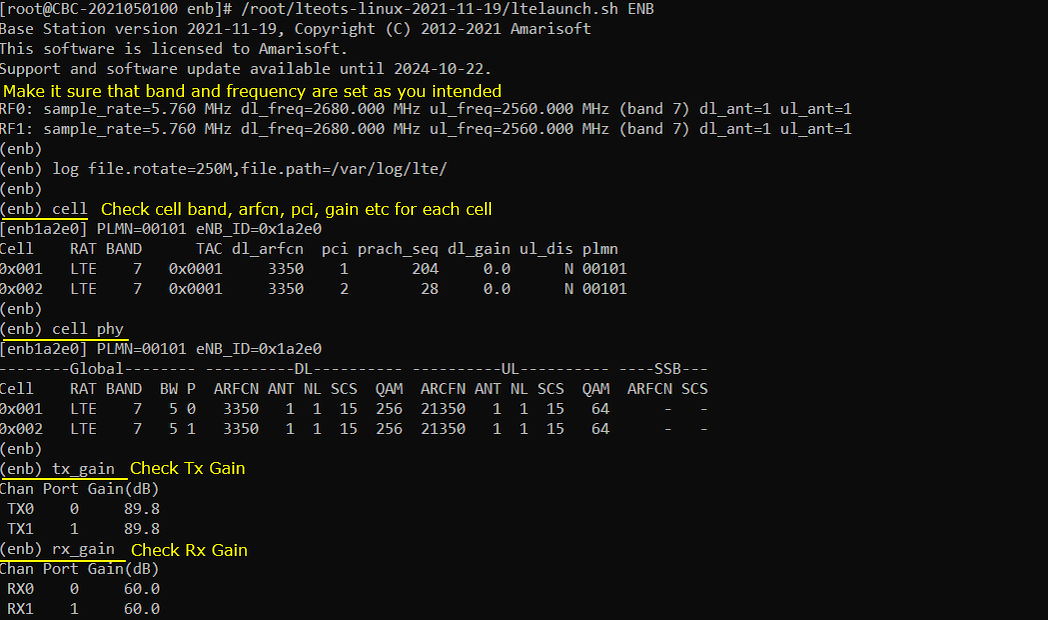
Start the LTE service and first check the basic cell status before starting the reselection test. At this stage, the purpose is not yet to trigger reselection. The purpose is to make sure that the two-cell configuration is loaded correctly and that both cells are operating as expected.
The first thing to check is the RF frequency information. In this example, RF0 and RF1 are both configured with the same downlink frequency, 2680 MHz, and the same band, Band 7. This is important because this test is for intra-frequency cell reselection. If the two cells are configured on different EARFCNs, the test becomes inter-frequency reselection, which follows a different measurement and reselection rule.
Next, check the cell list using the cell command. In this example, there are two LTE cells.
Cell 0x01 is configured on Band 7 with dl_arfcn 3350, PCI 1, PRACH root sequence 204, and DL gain 0.0.
Cell 0x02 is also configured on Band 7 with dl_arfcn 3350, PCI 2, PRACH root sequence 28, and DL gain 0.0.
This confirms that both cells are using the same EARFCN, but different PCIs. This is the expected configuration for this intra-frequency reselection test. The UE should be able to distinguish the two cells by PCI while measuring them on the same carrier frequency.
Then check the cell phy command. This gives a more detailed physical layer view of each cell. In this example, both cells are LTE Band 7, 5 MHz bandwidth, downlink ARFCN 3350, SCS 15 kHz, and downlink QAM 256. The uplink configuration also shows the corresponding uplink ARFCN 21350 with 15 kHz SCS and 64 QAM.
This confirms that the two cells have the same radio bandwidth and frequency configuration. So any reselection behavior observed later should mainly come from the relative cell power and reselection parameters, not from different frequency or bandwidth settings.
Finally, check tx_gain and rx_gain. In this example, TX0 and TX1 both show gain 89.8 dB. RX0 shows gain 60.0 dB. At this point, you do not need to change these values yet. Just remember the current gain settings because they define the starting RF power condition before you begin adjusting cell power for the reselection test.
So before starting the actual reselection procedure, the key checklist is this: both cells should be active, both cells should use the same band and EARFCN, the PCI of each cell should be different, and the current TX/RX gain values should be noted. Once these are confirmed, you can proceed to the UE camping and reselection test.
In summary,
- First, make it sure that band and frequencies of the two cells are same (this is to ensure the intra frequency criteria)
- Then make it sure that dl_arfcn of the two cell are same by checking the result of cell and cell phy.
- Lastly check out the result of tx_gain and rx_gain. At this point, you don't have to do anything about this. Just remember the current setting.
Configure the cell power so that the UE camps on cell 1 first.
In this step, cell 2 power is intentionally lowered before starting the UE attach or cell selection procedure. The command cell_gain 2 -30 reduces the downlink gain of cell 2 to -30 dB. As a result, cell 2 becomes much weaker than cell 1 from the UE point of view.
This makes the initial camping condition clear. Since cell 1 keeps its downlink gain at 0.0 dB and cell 2 is reduced to -30.0 dB, the UE should select cell 1 as the better suitable cell during initial cell selection.
After changing the gain, the cell command is used again to confirm the current cell status. In the result, cell 0x01 shows dl_gain 0.0, while cell 0x02 shows dl_gain -30.0. This confirms that the power difference between the two cells is applied correctly.
At this point, the test condition is prepared as follows.
Cell 1 is the strong cell.
Cell 2 is the weak cell.
Both cells are still on the same EARFCN 3350.
The UE is expected to camp on cell 1 first.
This step is important because reselection needs a known starting point. If both cells have similar power from the beginning, the UE may camp on either cell depending on timing, measurement fluctuation, or UE implementation. By lowering the power of cell 2 first, the test starts from a controlled and predictable condition.

Power on the UE and let it attach to cell 1 as shown below.
After lowering the power of cell 2, start the UE. The UE should detect both cells, but cell 1 should be selected because it has much stronger downlink power than cell 2.
In this example, the PRACH log shows cell=01. This means the random access procedure is performed toward cell 1. This is the first indication that the UE is trying to access cell 1, not cell 2.
Then the ue command confirms the current UE context. The UE is listed with Cell 0x001 and RNTI 0x003d. This means the UE is now connected through cell 1.
At this point, the starting condition for the reselection test is confirmed. The UE is attached to cell 1 while cell 2 is still configured as a weaker neighbor cell. This is the expected initial state before changing the power condition to trigger reselection.
So the important check here is simple. The UE should appear under cell 0x001. If the UE appears under cell 0x002 instead, it means the initial power condition was not strong enough to force the UE to start from cell 1, and you should reduce the power of cell 2 further or check the RF connection and gain setting again.

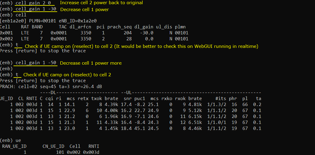
Increase the power of cell 2 and decrease the power of cell 1. Repeat this procedure until cell reselection happens.
In this step, the radio condition is intentionally reversed. Previously, cell 1 was stronger and cell 2 was weaker, so the UE selected cell 1. Now cell 2 is restored back to its original power, and cell 1 is gradually reduced.
First, cell_gain 2 0 is used to bring cell 2 power back to 0 dB. Then cell_gain 1 -30 is used to reduce the power of cell 1. After this change, the cell command confirms that cell 1 has dl_gain -30.0 and cell 2 has dl_gain 0.0.
At this moment, cell 2 is stronger than cell 1. However, reselection may not happen immediately. The UE needs to measure the neighbor cell, evaluate the reselection condition, and keep the condition satisfied for the required time. So it is normal that the UE may still stay on cell 1 for a short time.
The t command is used to check whether the UE has reselected to cell 2. In this example, after setting cell 1 to -30 dB, the UE did not immediately move to cell 2. Therefore, the test continues by decreasing cell 1 power further.
Next, cell_gain 1 -50 is applied. This makes cell 1 even weaker compared to cell 2. After this additional power change, the UE performs access on cell 2. The PRACH log shows cell=02, which means the UE is now trying to access cell 2.
The ue command confirms the final result. The UE is now listed under Cell 0x002. This means the UE has moved from cell 1 to cell 2. In other words, LTE intra-frequency cell reselection has successfully happened.
The important point is that reselection is not triggered simply by changing the gain command itself. The gain command only changes the RF condition. The actual reselection decision is made by the UE, based on its idle mode measurement, SIB reselection parameters, cell suitability condition, and reselection timer behavior.
So the practical test flow is:
- Start with UE camped on cell 1.
- Make cell 2 stronger than cell 1.
- Check whether the UE moves to cell 2.
- If it does not move yet, reduce cell 1 power further.
- Repeat until PRACH and UE status show that the UE is now on cell 2.
In this example, the final confirmation is clear. The UE was initially on cell 0x001, and after the power condition was changed, it moved to cell 0x002. This verifies LTE to LTE intra-frequency cell reselection based on cell power difference.
Log Analysis
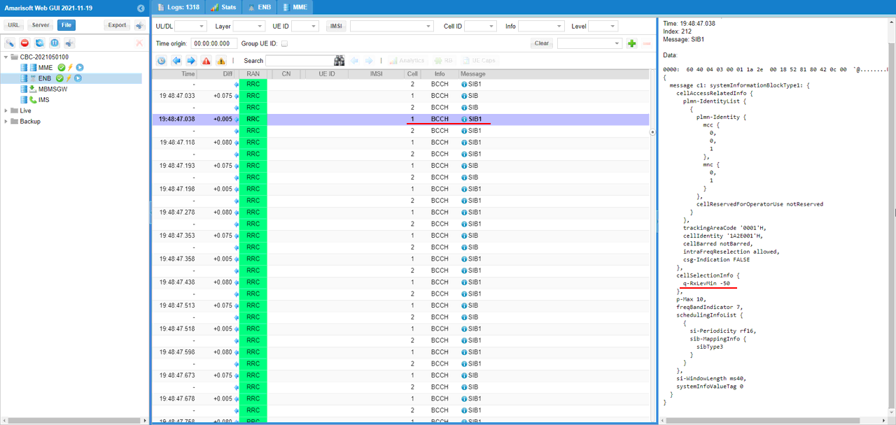
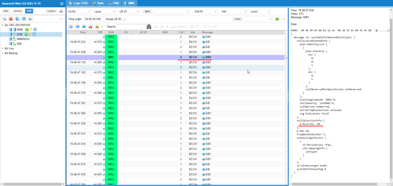
Now check the SIB1 message from the first cell and confirm the q-RxLevMin value in cellSelectionInfo.
This part is not directly showing the reselection event itself. Instead, it is used to confirm the initial cell selection condition broadcast by cell 1. Before analyzing why the UE camps on a cell or reselects to another cell, it is useful to check what the cell is actually broadcasting in SIB1.
In this example, the selected log is an RRC BCCH SIB1 message from cell 1. On the right side, the decoded SIB1 content shows cellSelectionInfo. Inside cellSelectionInfo, q-RxLevMin is set to -50.
This matches the value configured earlier in cell_default. It confirms that the UE receives q-RxLevMin = -50 from SIB1 of the first cell.
q-RxLevMin defines the minimum required received level for the UE to regard the cell as suitable for camping. So this value is used during the cell selection and cell suitability check. If the measured cell level is too low compared to this threshold, the UE should not treat the cell as a suitable serving cell.
In this test, q-RxLevMin was intentionally increased from the default value to -50. The purpose is to make the test easier to observe. With this higher minimum level, the UE needs a relatively stronger received signal to consider the cell suitable. This makes the camping and reselection behavior happen in a more visible power range when we manually change cell gain.
The important point here is that this SIB1 check is mainly for validating the initial cell selection condition. The actual intra-frequency reselection control is checked later through the reselection-related information in SIB3, but SIB1 gives the basic suitability condition that the UE must satisfy before camping on the LTE cell.
Now check the SIB1 message from the second cell and confirm the q-RxLevMin value in cellSelectionInfo.
This check is similar to the previous one, but this time the selected SIB1 message is from cell 2. The purpose is to confirm that the second cell also broadcasts the same basic cell selection condition.
In this example, the decoded SIB1 for cell 2 shows cellIdentity 1A2E002 and intraFreqReselection allowed. This confirms that this SIB1 belongs to the second LTE cell and that intra-frequency reselection is allowed for this cell as well.
Inside cellSelectionInfo, q-RxLevMin is set to -50. This is the same value as the first cell. This means both cell 1 and cell 2 are using the same minimum received level requirement for cell suitability.
This value is not the direct trigger for cell reselection. It is mainly used to decide whether the cell is suitable for the UE to camp on. However, it is still important to check this value because the UE cannot reselect to a cell that is not considered suitable.
In this test, both cells broadcast q-RxLevMin = -50. So when the UE later moves from cell 1 to cell 2, the reselection result is not caused by a different q-RxLevMin setting between the two cells. Instead, the main factor is the relative received power difference created by changing the cell gain.
So the key point from this log is that cell 2 is also a valid suitable LTE cell, intra-frequency reselection is allowed, and the q-RxLevMin value matches the intended configuration.
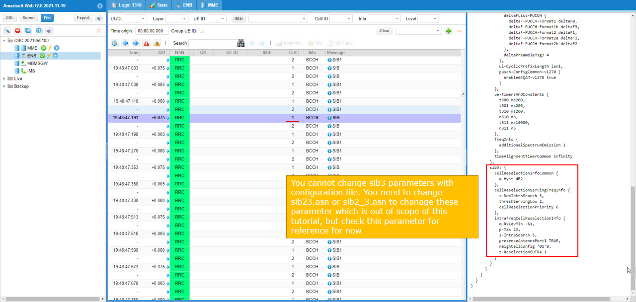
Check out the cellReselectionInformation in SIB3 of the first cell. The contents of these IEs cannot be configured by configuration parameter. You need to change this by hardcoding the IEs in the sib2_3.asn file.
This part shows the LTE reselection parameters broadcast by cell 1. Unlike q-RxLevMin in SIB1, these SIB3 parameters are directly related to cell reselection behavior.
In this example, the selected message is an RRC BCCH SIB message from cell 1. On the right side, SIB3 is decoded and the cellReselectionInfo section is shown.
cellReselectionInfoCommon includes q-Hyst 2dB. This value is used as a hysteresis margin for cell reselection. It helps prevent the UE from changing cells too easily when the serving cell and neighbor cell have similar signal levels. Because of this hysteresis, the neighbor cell usually needs to be sufficiently better than the serving cell before reselection can happen.
cellReselectionServingFreqInfo includes s-NonIntraSearch 3, threshServingLow 2, and cellReselectionPriority 6. These values describe the reselection behavior and priority of the current serving frequency. In this test, both cells are on the same frequency, so the priority value is the same frequency-layer priority used by the UE during idle mode evaluation.
intraFreqCellReselectionInfo includes q-RxLevMin -61, p-Max 23, s-IntraSearch 5, presenceAntennaPort1 TRUE, neighCellConfig 01, and t-ReselectionEUTRA 1.
Among these values, s-IntraSearch is important because it controls when the UE needs to perform intra-frequency neighbor cell measurement. t-ReselectionEUTRA is also important because it defines how long the reselection condition should remain satisfied before the UE actually moves to the target cell. In this example, t-ReselectionEUTRA is set to 1, so the UE does not reselect immediately at the first measurement result. It has to keep the reselection condition satisfied for the configured reselection time.
One important note is that these SIB3 values are not configured by the normal configuration parameters used earlier in this tutorial. To change these values, you need to modify the ASN file directly, such as sib2_3.asn. This is outside the main scope of this tutorial, so here we only check the values for reference.
The key point from this log is that cell 1 broadcasts the intra-frequency reselection parameters through SIB3. These parameters tell the UE how to evaluate neighbor cells on the same frequency, how much hysteresis should be applied, and how long the reselection condition should be maintained before the UE moves to another LTE cell.
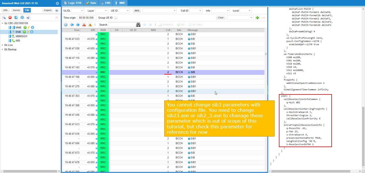
Check out the cellReselectionInformation in SIB3 of the second cell. The contents of these IEs cannot be configured by configuration parameter. You need to change this by hardcoding the IEs in the sib2_3.asn file.
This check is the same type of verification as the previous one, but this time it is done for cell 2. The purpose is to confirm that the second cell also broadcasts the expected LTE cell reselection parameters.
In this example, the selected SIB message belongs to cell 2. On the right side, SIB3 is decoded and the cellReselectionInfo section is shown.
cellReselectionInfoCommon shows q-Hyst 2dB. This means cell 2 also applies the same reselection hysteresis value as cell 1. This hysteresis helps avoid unnecessary ping-pong reselection when the measured power difference between two cells is small.
cellReselectionServingFreqInfo includes s-NonIntraSearch 3, threshServingLow 2, and cellReselectionPriority 6. These values define the reselection-related behavior for the serving frequency. Since this test is intra-frequency reselection, both cells are on the same EARFCN and the UE evaluates the neighbor cell within the same frequency layer.
intraFreqCellReselectionInfo includes q-RxLevMin -61, p-Max 23, s-IntraSearch 5, presenceAntennaPort1 TRUE, neighCellConfig 01, and t-ReselectionEUTRA 1.
s-IntraSearch controls when the UE should perform intra-frequency neighbor cell measurement. t-ReselectionEUTRA controls how long the reselection condition should remain satisfied before the UE actually reselects to the other LTE cell. In this example, t-ReselectionEUTRA is set to 1, so the UE needs to keep the reselection condition valid for the configured time before moving.
The important point is that these SIB3 parameters are not changed by the normal configuration parameters used in this example. If you want to change these values, you need to modify the ASN file directly, such as sib2_3.asn. This is outside the scope of this tutorial, so we only check the values here as a reference.
From this log, we can confirm that cell 2 broadcasts the same reselection-related parameters as cell 1. Therefore, when the UE moves from cell 1 to cell 2 in this test, the main reason is not a difference in SIB3 configuration between the two cells. The main reason is the change in relative cell power created by increasing cell 2 power and decreasing cell 1 power.
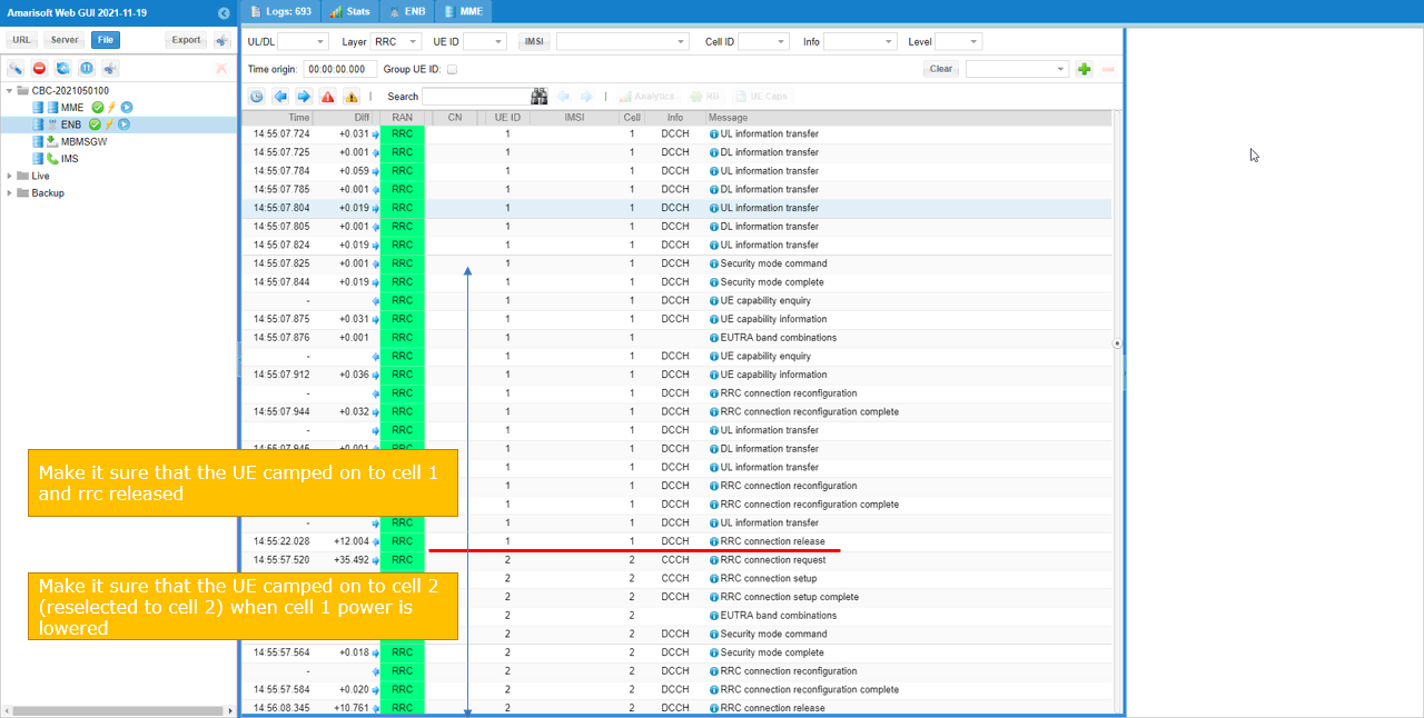
Power on UE and let UE camp onto the first cell, and trigger cell reselection by tweaking the cell power. If the cell reselection is properly performed, you would see that UE camp onto the second cell after releasing the first cell.
In this log, the first part shows that the UE initially camps on cell 1. The RRC messages are exchanged with Cell 1, and the UE goes through the normal connection procedure. You can see messages such as RRC connection request, RRC connection setup, RRC connection setup complete, UE capability enquiry, UE capability information, security mode command, security mode complete, and UL information transfer. This confirms that the UE is attached through cell 1 at the beginning of the test.
After confirming that the UE is on cell 1, the cell power is changed. Cell 2 power is increased or restored, and cell 1 power is lowered. This creates a condition where cell 2 becomes better than cell 1 from the UE measurement point of view.
The important event in the middle of the log is RRC connection release on cell 1. This means the UE is released from connected mode and returns to idle mode. Cell reselection is an idle mode mobility procedure, so this release is important. After the UE becomes idle, it can evaluate the serving cell and neighbor cell using the reselection rules broadcast in SIB3.
After the release from cell 1, the UE performs access on cell 2. In the lower part of the log, the RRC messages are now shown with Cell 2. You can see RRC connection request, RRC connection setup, RRC connection setup complete, EUTRA band combinations, security mode command, security mode complete, and RRC connection reconfiguration on cell 2.
This confirms that the UE has moved from cell 1 to cell 2 after the cell power was changed. In other words, the UE first camped on cell 1, then after cell 1 became weaker and cell 2 became stronger, the UE reselected to cell 2.
One important thing to remember is that this is not handover. In handover, the UE stays in connected mode and the network commands the UE to move to another cell. In this test, the UE is released first, then the UE itself performs idle mode reselection based on the cell measurement and reselection parameters. That is why the key sequence is cell 1 connection, RRC release, then new access on cell 2.
So the main confirmation points in this log are as follows.
- The UE is initially connected on cell 1.
- The first connection is released.
- After changing the cell power, the UE accesses cell 2.
- The new RRC connection is established on cell 2.
This shows that LTE intra-frequency cell reselection was successfully triggered by changing the relative power between the two LTE cells.
Test 2 : LTE to LTE Reselection, Inter Frequency, Priority Based Reselection
In this test, I will show you how to configure and validate the cell reselection between two LTE cells with the same frequency (Intra Frequency) based on Priority configured in RRC Connection Release message.
Configuration
I used enb-2cell-resel-priority.cfg which is copied and modified from enc-2cell-ho.cfg .
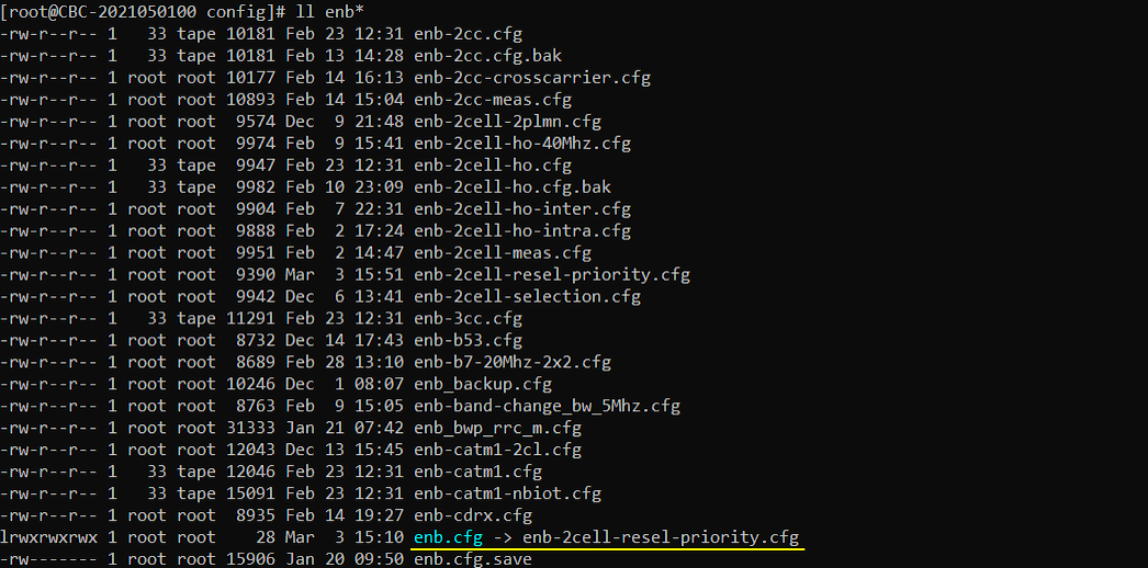
For this test, I have created a few new asn files as below : lte_resel_priority.asn is completely new file and sib_2_3_5.asn is copied and modified from sib2_3.asn file.
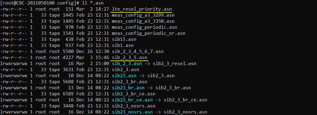
For mme, everything is same as default setting.

Followings are configurations in enb-2cell-resel-priority.cfg
This part defines the basic configuration for Test 2, which is LTE to LTE inter-frequency reselection based on priority.
The overall structure is similar to Test 1. N_CELL is set to 2, so the eNB runs two LTE cells. This should not be changed because the rest of the configuration expects two cells.
TDD is set to 0, so this test uses LTE FDD operation. N_RB_DL is set to 25, which means each LTE cell uses 5 MHz downlink bandwidth.
N_ANTENNA_DL and N_ANTENNA_UL are both set to 1. So both downlink and uplink use a simple single-antenna configuration. This keeps the test focused on cell reselection behavior, not on MIMO operation.
CHANNEL_SIM is set to 0, meaning the channel simulator is disabled. Because of this, the test result is mainly controlled by the configured cell frequency, cell power, and reselection priority information, not by fading or simulated radio channel conditions.
NG_ENB is set to 0. This means the test uses a normal LTE eNB configuration, not ng-eNB operation.
The most important point for this test is not shown in this common parameter block yet. The key difference comes later in the per-cell frequency configuration and in the reselection priority information. Unlike Test 1, the two LTE cells should be configured on different EARFCNs. Then the UE can perform inter-frequency reselection after it receives the priority information and is released to idle mode.

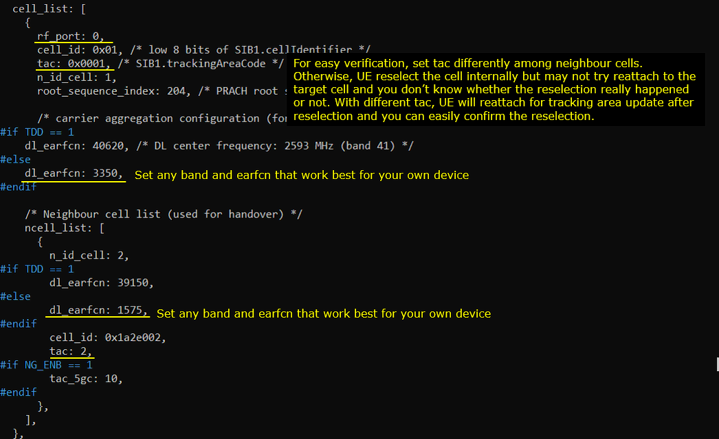
To make the condition for inter frequency, set different frequecies to each of the cells. And for easy verification, set tac (tracking area code) differently among neighbour cells. Otherwise, UE reselect the cell internally but may not try to reattach to the target cell and you don't know whether the reselection really happened or not. With different tac, UE will reattach for tracking area update after reselection and you can easily confirm the reselection.
This part configures cell 1 and its neighbor cell for the inter-frequency reselection test.
The first important point is that cell 1 is mapped to rf_port 0. This means the first LTE cell is transmitted through RF port 0. cell_id is set to 0x01, tac is set to 0x0001, and n_id_cell is set to 1. So this cell uses PCI 1 and tracking area code 1.
For FDD, dl_earfcn of cell 1 is set to 3350. In this example, this corresponds to LTE Band 7 with downlink center frequency 2680 MHz. You can change this EARFCN depending on the LTE band supported by your own UE, but for this test the two cells should not use the same EARFCN. They should be on different frequencies to create an inter-frequency reselection condition.
The neighbor cell is configured under ncell_list. Here, n_id_cell is set to 2, meaning the neighbor cell uses PCI 2. For FDD, the neighbor cell dl_earfcn is set to 1575. This is different from cell 1, so the UE has to evaluate another LTE frequency layer when it performs reselection.
Another important setting is tac. The serving cell has tac 1, while the neighbor cell is configured with tac 2. This is intentionally done for easier verification.
If both cells use the same tracking area code, the UE may reselect internally from cell 1 to cell 2, but it may not immediately perform a new tracking area update or reattach procedure. In that case, it can be difficult to confirm from the log whether reselection really happened.
By setting different TAC values, the UE detects that it has moved into a different tracking area after reselection. Then it performs a Tracking Area Update. This creates a clear signaling trace, so it becomes much easier to confirm that the UE actually reselected to the target cell.
So the key points in this configuration are:
- cell 1 is mapped to RF port 0.
- cell 1 uses PCI 1 and TAC 1.
- cell 1 uses EARFCN 3350.
- cell 2 is configured as a neighbor cell.
- cell 2 uses PCI 2 and TAC 2.
- cell 2 uses a different EARFCN, 1575.
This prepares the test condition for LTE inter-frequency reselection. The UE starts from cell 1 on one LTE frequency, then later it can reselect to cell 2 on another LTE frequency based on the priority information and target cell signal condition.
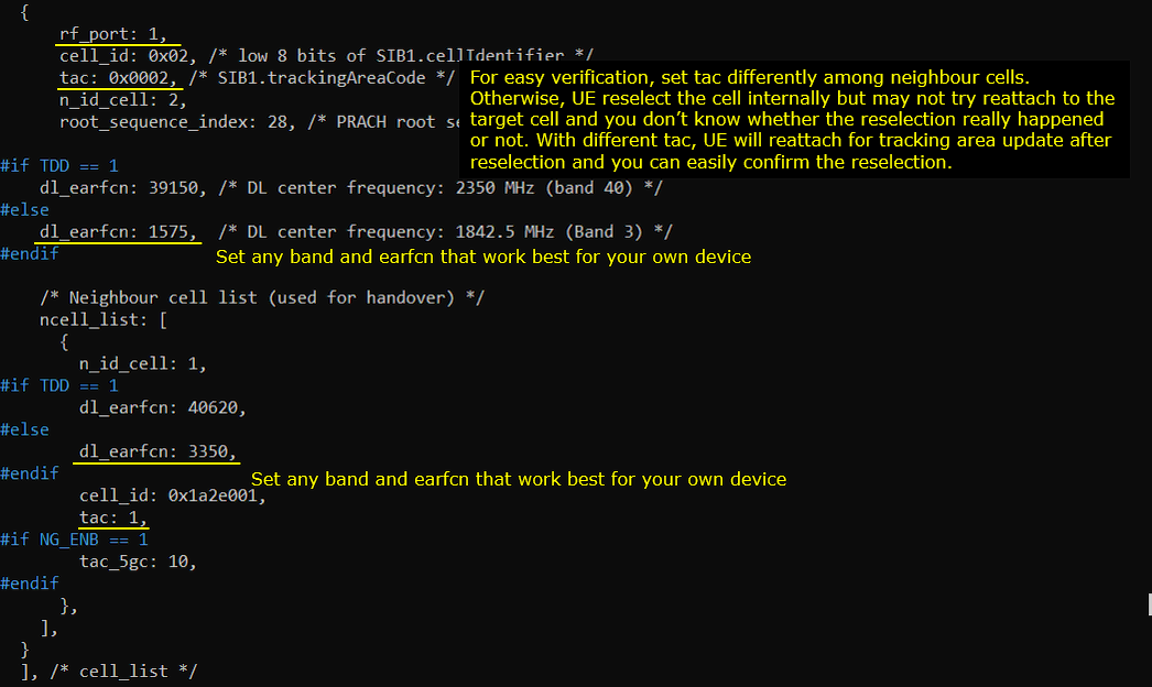
This part configures cell 2 and its neighbor cell for the inter-frequency reselection test.
Here, cell 2 is mapped to rf_port 1. This means the second LTE cell is transmitted through RF port 1. cell_id is set to 0x02, tac is set to 0x0002, and n_id_cell is set to 2. So this cell uses PCI 2 and tracking area code 2.
For FDD, dl_earfcn of cell 2 is set to 1575. This corresponds to LTE Band 3 with downlink center frequency 1842.5 MHz. This is different from the EARFCN used by cell 1, which was 3350. Because the two cells use different EARFCNs, this test becomes an inter-frequency reselection case.
The highlighted comment reminds you to select a band and EARFCN that work well with your own UE. This is important because inter-frequency reselection cannot be tested unless the UE supports both frequency bands. If the UE does not support the target band, it will not be able to find or reselect to the second cell.
The neighbor cell list is configured under ncell_list. In this cell configuration, n_id_cell is set to 1, meaning cell 1 is defined as the neighbor cell of cell 2. For FDD, the neighbor dl_earfcn is set to 3350, which is the EARFCN of cell 1. This creates a symmetric neighbor relation between the two cells.
The TAC value is also intentionally different. Cell 2 uses tac 2, while cell 1 uses tac 1. This makes reselection easier to verify. When the UE reselects from one cell to the other, it also moves to a different tracking area. Because of this, the UE should perform a Tracking Area Update after reselection. This gives a clear signaling indication that the UE actually moved to the target cell.
So the key points in this configuration are:
- cell 2 is mapped to RF port 1.
- cell 2 uses PCI 2 and TAC 2.
- cell 2 uses EARFCN 1575.
- cell 1 is configured as the neighbor cell of cell 2.
- cell 1 uses PCI 1 and TAC 1.
- cell 1 uses EARFCN 3350.
With this setup, the two cells are configured on different LTE frequencies and different tracking areas. This makes it suitable for testing LTE inter-frequency reselection and makes the reselection result easier to confirm from the UE signaling log.
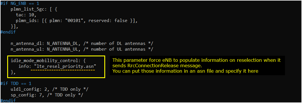
Configure idle_mode_mobility_control parameter with the asn file that carries frequencies and priorities of each cells.
This part configures idle_mode_mobility_control. This is one of the key parts of the priority-based inter-frequency reselection test.
In this example, idle_mode_mobility_control is configured with an external ASN file, lte_resel_priority.asn. This file contains the reselection priority information that the eNB will include when it sends the RRC Connection Release message to the UE.
This is important because priority-based reselection is not controlled only by the cell frequency setting. The UE needs to know which frequency has higher priority and which frequency has lower priority. That information is delivered to the UE as idle mode mobility control information.
When the eNB releases the UE from RRC connected mode, it can include cell reselection priority information in the RRC Connection Release message. After receiving this message, the UE enters idle mode and uses the provided frequency priority information to decide which frequency layer it should camp on.
In this test, the two LTE cells are configured on different EARFCNs. So the UE needs inter-frequency reselection information. The ASN file specified here carries the frequency and priority information for those LTE frequencies.
The important behavior is as follows.
- The UE first connects to the initial cell.
- The eNB sends RRC Connection Release.
- The release message includes idle mode mobility control information from lte_resel_priority.asn.
- The UE enters idle mode.
- The UE evaluates the configured LTE frequencies and their priorities.
- If the target frequency has higher priority and the radio condition is good enough, the UE reselects to the target cell.
So this configuration forces the eNB to populate reselection priority information in the RRC Connection Release message. Without this part, the UE may not receive the intended priority information, and the inter-frequency priority-based reselection behavior may not happen as expected.
The key point is that the actual priority list is not written directly in this main configuration section. It is stored in the ASN file. This main configuration only tells the eNB which ASN file should be used when generating the idle mode mobility control information.
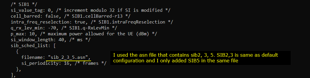
I added sib5 to the list of broadcast SIB in order to configure interfrequency cell reselection criteria. You can do this by assiging an asn file that carries all the sibs that you want to broadcast.
This part adds SIB5 to the broadcast SIB list so that the UE can receive inter-frequency reselection information.
In LTE, SIB3 mainly provides common reselection parameters for the serving frequency. But for inter-frequency reselection, the UE also needs information about other LTE frequencies. This information is carried in SIB5.
In this example, the SIB scheduling list uses sib_2_3_5.asn. This ASN file includes SIB2, SIB3, and SIB5 together. SIB2 and SIB3 are mostly the same as the default configuration, and SIB5 is added to support the inter-frequency reselection test.
This is important because the two cells in this test are configured on different EARFCNs. The UE cannot evaluate the target LTE frequency properly unless it receives the inter-frequency carrier frequency information and reselection criteria. SIB5 provides this information.
The SIB periodicity is set to 16 frames. This means the UE can periodically receive the SIB information, including SIB5, while it is camping on the LTE cell.
So there are two sources of reselection information in this test.
SIB5 broadcasts inter-frequency reselection information from the cell.
RRC Connection Release provides idle mode mobility control information using the ASN file configured earlier.
Together, these allow the UE to know which LTE frequencies should be considered, what priority should be applied, and whether the target inter-frequency cell satisfies the reselection condition.
The key point is that SIB5 should be included in the broadcast SIB list for inter-frequency reselection. Without SIB5, the UE may not have enough information to search and evaluate the target LTE frequency layer correctly.
I removed measurement control settings to prevent eNB from triggering handover.
This part removes the measurement control settings so that the eNB does not trigger handover.
In the original two-cell handover configuration, measurement control may be included. In that case, the eNB can configure UE measurements and may trigger connected-mode handover when the target cell becomes better. But this test is not for handover. This test is for idle-mode cell reselection.
Because of that, the measurement control part is removed from the DRB configuration area. Only the DRB configuration remains. This prevents the eNB from actively controlling UE mobility while the UE is in connected mode.
This distinction is important.
Handover is network-controlled mobility. The UE stays in RRC connected mode, reports measurements, and the eNB decides when to move the UE to another cell.
Cell reselection is UE-controlled idle-mode mobility. The UE is released from RRC connected mode, enters idle mode, checks the reselection priority and frequency information, and then selects the best suitable cell by itself.
So for this test, we intentionally avoid connected-mode handover. The UE should first connect to the initial cell, then receive RRC Connection Release with idle mode mobility control information, and finally perform reselection in idle mode.
The key point is that removing measurement control helps make the test result clean. If the UE moves to another cell after this change, it is more likely to be caused by idle-mode reselection, not by eNB-triggered handover.

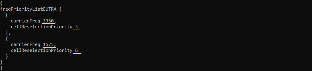
Following is the configuration in lte_resel_priority.asn . This file carries the carrierFreq (Carrier Frequency) and Priority (cellReselectionPriority) for each cell.
This file defines the LTE frequency priority list used for idle mode mobility control.
In this example, freqPriorityListEUTRA contains two LTE carrier frequencies. The first carrierFreq is 3350 and its cellReselectionPriority is 3. The second carrierFreq is 1575 and its cellReselectionPriority is 6.
This means EARFCN 1575 has higher reselection priority than EARFCN 3350. In LTE, a larger cellReselectionPriority value means a higher priority frequency layer. So after the UE receives this information and goes back to idle mode, it should prefer the LTE frequency 1575 over 3350, as long as the target cell satisfies the required radio condition.
This is the main control point of this test. The UE may initially camp on cell 1 using EARFCN 3350. But when the eNB releases the UE and includes this priority information in the RRC Connection Release message, the UE learns that EARFCN 1575 has higher priority. Then the UE searches and evaluates the cell on EARFCN 1575. If the signal level is good enough, the UE reselects to cell 2.
So the expected behavior is:
- The UE first connects to cell 1 on EARFCN 3350.
- The eNB sends RRC Connection Release with idle mode mobility control information.
- The release message includes carrierFreq 3350 with priority 3 and carrierFreq 1575 with priority 6.
- The UE enters idle mode and gives higher preference to EARFCN 1575.
- The UE reselects to cell 2 on EARFCN 1575 if the cell is suitable.
The key point is that this test is not mainly based on making one cell much stronger than the other. It is based on reselection priority. Since EARFCN 1575 has higher priority than EARFCN 3350, the UE is guided to move from the lower-priority frequency to the higher-priority frequency after release.
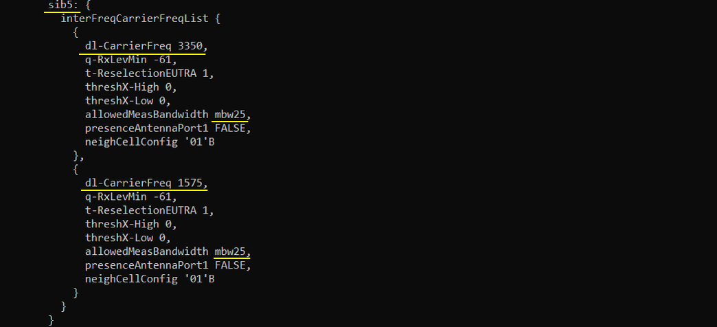
Following is sib5 that is added in sib_2_3_5.asn, SIB4 carries the IE interFreqCarrierFreqList which specifies various cell parameters of each cell to help with cell reselection.
This part shows the SIB5 configuration added in sib_2_3_5.asn.
SIB5 is used to broadcast inter-frequency LTE reselection information. In this test, the UE needs to know that there are other LTE carrier frequencies to search and evaluate. That information is provided through interFreqCarrierFreqList.
In this example, interFreqCarrierFreqList includes two LTE carrier frequencies.
The first entry is dl-CarrierFreq 3350. This is the frequency used by cell 1. For this frequency, q-RxLevMin is set to -61, t-ReselectionEUTRA is set to 1, threshX-High is set to 0, threshX-Low is set to 0, and allowedMeasBandwidth is set to mbw25.
The second entry is dl-CarrierFreq 1575. This is the frequency used by cell 2. It also uses q-RxLevMin -61, t-ReselectionEUTRA 1, threshX-High 0, threshX-Low 0, and allowedMeasBandwidth mbw25.
q-RxLevMin defines the minimum required received level for a cell on that inter-frequency carrier to be considered suitable. In this example, both frequencies use the same value, so the test does not create different suitability conditions between the two frequencies.
t-ReselectionEUTRA is set to 1. This means the reselection condition has to remain valid for the configured reselection time before the UE actually moves to the target frequency.
threshX-High and threshX-Low are both set to 0. These parameters are used in inter-frequency reselection evaluation, especially when the UE compares higher-priority or lower-priority frequencies. In this test, the priority difference is mainly provided by the priority list, while these threshold values are kept simple.
allowedMeasBandwidth is set to mbw25. This matches the 5 MHz LTE bandwidth used in this test, since 25 RB corresponds to 5 MHz.
presenceAntennaPort1 is set to FALSE and neighCellConfig is set to 01B. These parameters provide additional information about the neighboring frequency layer and cell configuration.
The key point is that SIB5 tells the UE what LTE frequencies are available for inter-frequency reselection and what basic reselection criteria should be applied to those frequencies. In this test, EARFCN 3350 and EARFCN 1575 are both included, so the UE can evaluate both frequency layers after it is released to idle mode.
Together with the priority information delivered in RRC Connection Release, this SIB5 configuration allows the UE to reselect from the lower-priority frequency to the higher-priority frequency when the target cell satisfies the reselection condition.
Perform the test
Before triggering reselection, first check the physical configuration of each cell and confirm that the two cells are configured as intended.
In this example, the cell phy result shows two LTE cells.
Cell 0x001 is configured on LTE Band 7 with downlink ARFCN 3350. The bandwidth is 5 MHz, and it uses RF port 0. This is the first cell, which is used as the initial serving cell in this test.
Cell 0x002 is configured on LTE Band 3 with downlink ARFCN 1575. The bandwidth is also 5 MHz, and it uses RF port 1. This is the second cell, which is used as the target cell for inter-frequency reselection.
This confirms that the two cells are not using the same LTE frequency. Cell 1 uses EARFCN 3350, while cell 2 uses EARFCN 1575. Therefore, this test condition is correctly configured as inter-frequency reselection.
The uplink ARFCN is also different for each cell. Cell 1 uses UL ARFCN 21350, and cell 2 uses UL ARFCN 19575. This matches the different LTE bands used by the two cells.
The important point here is that both cells are active, but they are operating on different frequency layers. This is the required condition for priority-based inter-frequency reselection. After this is confirmed, the next step is to power on the UE, let it camp on the first cell, release the UE with reselection priority information, and then check whether the UE moves to the higher-priority frequency.

Set the cell gain of the two cells in such a way that UE camp on cell 1 first (you may need to set a little bit different gain values depending on your test setup)
In this step, the purpose is to create a clear initial condition before testing priority-based inter-frequency reselection. Even though cell 2 has higher reselection priority later, the UE should first start from cell 1 so that we can clearly observe the movement from cell 1 to cell 2.
In this example, cell 1 gain is set to -10 dB and cell 2 gain is set to -20 dB. This makes cell 1 slightly stronger than cell 2 from the UE point of view. The exact gain values may need to be adjusted depending on your RF setup, cable loss, attenuator, antenna condition, and UE sensitivity.
After applying the gain values, the cell command is used to confirm the current configuration.
Cell 0x001 is on EARFCN 3350, PCI 1, TAC 0x0001, and dl_gain -10.0.
Cell 0x002 is on EARFCN 1575, PCI 2, TAC 0x0002, and dl_gain -20.0.
This confirms that cell 1 is configured with higher power than cell 2. So when the UE is powered on, it is expected to select and camp on cell 1 first.
The important point is that this gain setting is only for the initial camping condition. The main purpose of this test is not to force reselection only by power difference. The reselection target is mainly controlled by the frequency priority information. However, starting from cell 1 makes the test result easier to understand because we can later verify that the UE moved from the lower-priority EARFCN 3350 to the higher-priority EARFCN 1575 after RRC release.

Power on the UE and confirm that the UE camps on cell 1.
After setting the gain values, start the UE and check the trace output. In this example, the PRACH log shows cell=01. This means the UE performs random access toward cell 1.
The trace also shows the UE activity under CL 001. This confirms that the UE is currently connected through cell 1. The RNTI is shown as 003d, meaning the UE has successfully established radio access on this cell.
This is the expected starting condition for this test. Cell 1 is using EARFCN 3350 and has lower reselection priority. Cell 2 is using EARFCN 1575 and has higher reselection priority, but at this moment the UE is still camped on cell 1 because the initial RF condition was adjusted to make cell 1 more favorable.
So the important confirmation here is:
The PRACH is sent to cell 01.
The UE appears under CL 001.
The UE is not yet on cell 2.
Once this condition is confirmed, the next step is to release the UE with idle mode mobility control information. After the release, the UE should use the priority information and try to move to the higher-priority frequency, which is EARFCN 1575 on cell 2.

After a while, you should see that the UE attaches to cell 2. At this point, you should not conclude immediately that reselection happened only from this screen. You need to check the detailed log later to confirm whether the movement to cell 2 was really caused by idle mode cell reselection or by some other procedure.
In this trace, the UE is now shown under CL 002. This means the UE is no longer accessing cell 1. It is now using cell 2.
This is the expected result for this test. Cell 2 is configured on EARFCN 1575, and this frequency has higher reselection priority than EARFCN 3350. After the UE receives the priority information and returns to idle mode, it should evaluate the higher-priority frequency. If the cell on that frequency is suitable, the UE can reselect to cell 2.
The important observation here is that the UE moved from cell 1 to cell 2 without connected-mode handover. Since measurement control was removed earlier, the eNB should not trigger handover. Therefore, the expected mobility mechanism is idle mode reselection.
Also, since cell 1 and cell 2 use different TAC values, the UE should perform a Tracking Area Update after moving to cell 2. This makes it easier to verify the reselection result in the signaling log.
So this screen gives the first confirmation that the UE is now on cell 2. But the final confirmation should come from the log analysis. In the log, you should check that the UE received RRC Connection Release with idle mode mobility control information, then accessed cell 2, and then performed Tracking Area Update due to the TAC change.

Log Analysis
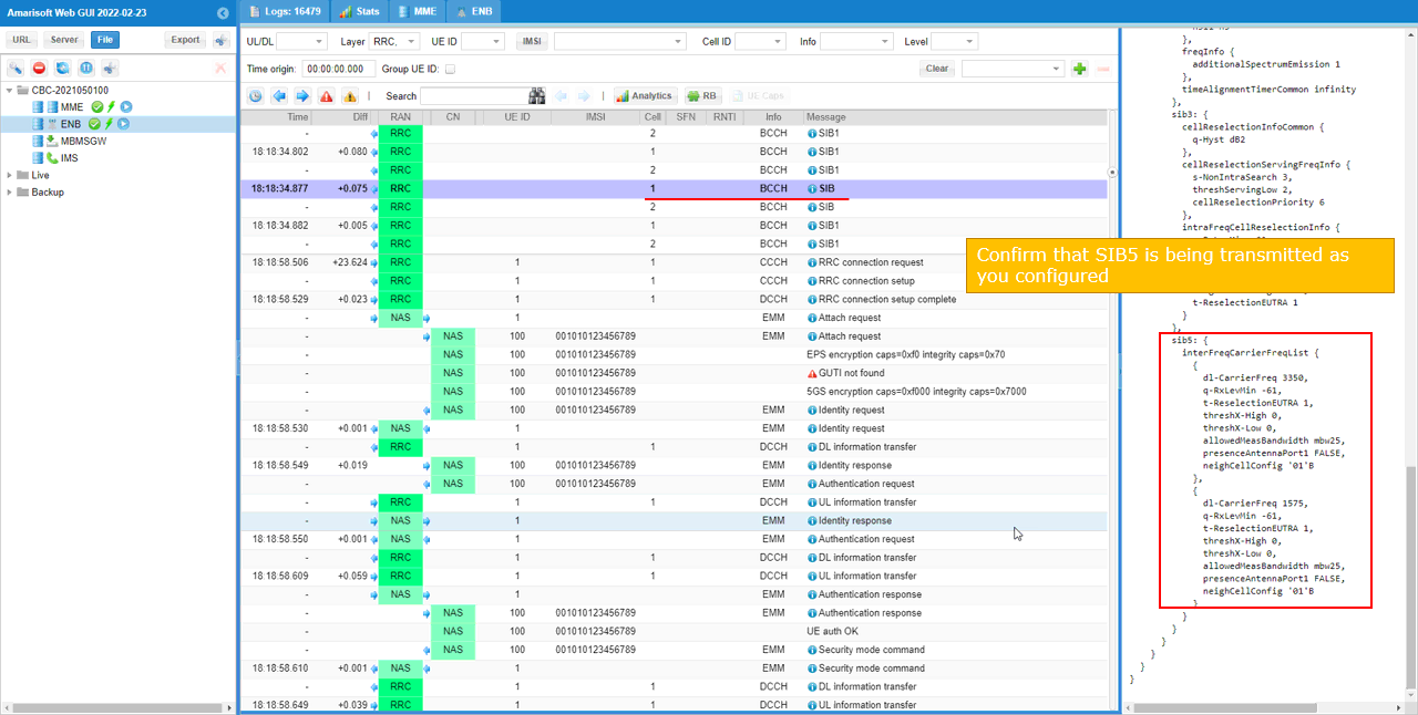
Check whether SIB5 is being transmitted and whether it is configured as intended.
In this log, the selected broadcast message includes SIB5. This is important because SIB5 is the system information block that carries inter-frequency LTE reselection information.
On the decoded message side, SIB3 and SIB5 are shown. SIB3 includes the common reselection parameters for the serving cell, while SIB5 includes interFreqCarrierFreqList. This confirms that the ASN file sib_2_3_5.asn is being used correctly and that SIB5 is actually broadcast by the cell.
Inside SIB5, two inter-frequency carrier entries are shown.
The first entry is dl-CarrierFreq 3350. This corresponds to the frequency of cell 1. It includes q-RxLevMin -61, t-ReselectionEUTRA 1, threshX-High 0, threshX-Low 0, allowedMeasBandwidth mbw25, presenceAntennaPort1 FALSE, and neighCellConfig 01B.
The second entry is dl-CarrierFreq 1575. This corresponds to the frequency of cell 2. It uses the same basic reselection parameters: q-RxLevMin -61, t-ReselectionEUTRA 1, threshX-High 0, threshX-Low 0, allowedMeasBandwidth mbw25, presenceAntennaPort1 FALSE, and neighCellConfig 01B.
This confirms that both LTE frequencies used in this test are advertised to the UE through SIB5. Therefore, when the UE is released to idle mode, it has the required information to search and evaluate the other LTE frequency.
This log does not yet prove that reselection happened. It only proves that the inter-frequency reselection information is being broadcast correctly. The actual reselection confirmation should be checked later from the RRC Connection Release message and from the UE access on the second cell.
The key point from this log is that SIB5 is present, and it contains both EARFCN 3350 and EARFCN 1575. So the UE has the required inter-frequency carrier information for this priority-based reselection test.
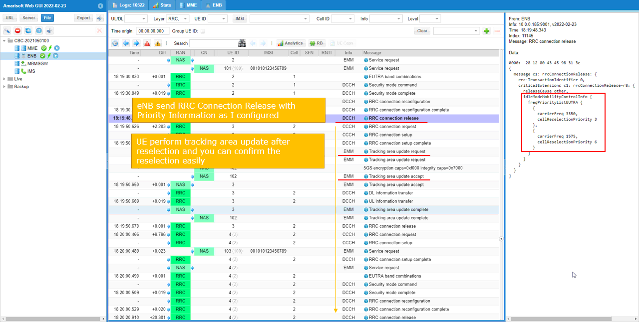
Following log shows the point where cell reselection happens. First RRC Connection Release specifies the cell reslection priority of each cell. Then UE reselect the cell based on the priority and camp onto the reselected cell.
This log shows the point where priority-based inter-frequency cell reselection happens.
First, the UE is connected on cell 1. Then the eNB sends RRC Connection Release. This is the important trigger point for this test because the release message includes idleModeMobilityControlInfo.
Inside idleModeMobilityControlInfo, freqPriorityListEUTRA is included. This list provides the LTE carrier frequency priority information to the UE.
carrierFreq 3350 is assigned cellReselectionPriority 3.
carrierFreq 1575 is assigned cellReselectionPriority 6.
This means EARFCN 1575 has higher priority than EARFCN 3350. After receiving this RRC Connection Release message, the UE enters idle mode and uses this priority information for cell reselection.
After the release, the UE evaluates the configured LTE frequencies. Since EARFCN 1575 has higher priority and the cell on that frequency satisfies the reselection condition, the UE selects cell 2.
The next important confirmation is the Tracking Area Update. After reselection, the UE sends Tracking area update request. This happens because cell 1 and cell 2 were configured with different TAC values. Cell 1 uses TAC 1 and cell 2 uses TAC 2. So when the UE moves to cell 2, it detects that the tracking area has changed and performs TAU.
This TAU procedure makes the reselection result easy to verify. If both cells had the same TAC, the UE might reselect internally, but there might not be an obvious NAS signaling procedure immediately after reselection. By using different TAC values, the log clearly shows that the UE moved to the second cell.
So the key sequence in this log is:
- The UE is connected on cell 1.
- The eNB sends RRC Connection Release.
- The release message includes idleModeMobilityControlInfo.
- EARFCN 3350 has priority 3.
- EARFCN 1575 has priority 6.
- The UE enters idle mode and evaluates the higher-priority frequency.
- The UE reselects to cell 2.
- The UE performs Tracking Area Update because the TAC changed.
This confirms that the movement from cell 1 to cell 2 is not a connected-mode handover. It is idle-mode LTE inter-frequency reselection based on the priority information delivered in RRC Connection Release.
RRC / NAS Signaling
RrcConnectionRelease
: This is the RrcConnectionRelease message sent by eNB to configure Reselection Priority. (
{
message c1: rrcConnectionRelease: {
rrc-TransactionIdentifier 0,
criticalExtensions c1: rrcConnectionRelease-r8: {
releaseCause other,
idleModeMobilityControlInfo {
freqPriorityListEUTRA {
{
carrierFreq 3350,
cellReselectionPriority 3
},
{
carrierFreq 1575,
cellReselectionPriority 6
}
}
}
}
}
}