Head Acoustics
The purpose of this test is to evaluate the DUT’s end-to-end voice performance under fully controlled and repeatable conditions by combining a real cellular RF connection from the AMARI Callbox with standardized acoustic coupling through the HMS II.3 head-and-torso simulator and precise signal generation/recording through labCORE. By driving known reference signals into the DUT (send path) and capturing the DUT’s reproduced audio (receive path) while the call is carried over the Callbox network, the setup makes it possible to measure codec behavior, loudspeaker and microphone quality, echo/noise processing, level handling, and overall speech transmission performance as it would occur in an actual cellular call, but with laboratory-level control and traceability.
Table of Contents
Introduction
End-to-end voice performance testing in cellular devices is a critical process that ensures high-quality speech communication under real-world conditions while leveraging the repeatability and control of a laboratory environment. This methodology integrates advanced test equipmentâ€including the AMARI Callbox for emulating a genuine cellular RF network, the HMS II.3 head-and-torso simulator for standardized acoustic coupling, and labCORE for precision audio signal generation and recordingâ€to create a comprehensive and controlled testbed. By injecting reference audio signals into the device under test (DUT) and analyzing the audio captured from the DUT during a live cellular call, engineers can accurately assess codec functionality, loudspeaker and microphone fidelity, acoustic echo and noise suppression mechanisms, and overall speech transmission characteristics. This approach enables precise identification and evaluation of factors affecting speech quality, ensuring that devices deliver optimal performance in real network scenarios. The blend of RF emulation and standardized acoustic interfacing provides traceable, reproducible results essential for device certification, regulatory compliance, and product development. Such testing forms a cornerstone in the development lifecycle of mobile devices, bridging the gap between laboratory analysis and user experience in the field.
-
Technology Context
- The setup combines cellular RF emulation (AMARI Callbox), standardized acoustic interfaces (HMS II.3), and advanced audio analysis (labCORE) to replicate real-world calling conditions with laboratory-level precision.
- Key concepts include end-to-end voice quality assessment, standardized acoustic coupling, codec behavior analysis, and the evaluation of audio processing algorithms such as echo and noise suppression.
- Architecturally, the test arrangement places the DUT in a controlled cellular environment while maintaining standardized audio pathways, enabling comprehensive testing from the physical layer through to the audio application layer.
-
Relevance and Importance
- Ensures devices meet industry standards for voice quality and performance, a critical factor in user satisfaction and regulatory approval.
- Facilitates identification and resolution of audio issues before commercial release, reducing post-market failures and support costs.
- Provides a repeatable and traceable testing process essential for benchmarking, certification, and product development.
-
What Learners Will Gain
- In-depth understanding of end-to-end voice performance testing methodologies for cellular devices.
- Practical knowledge of configuring and operating advanced RF and audio test equipment.
- Skills to interpret test results and apply them to device optimization and troubleshooting.
- Awareness of the standards and best practices governing speech quality evaluation in telecommunications.
-
Prerequisite Knowledge or Skills
- Fundamental understanding of cellular network architecture and mobile device operation.
- Familiarity with basic audio engineering principles, including signal generation and measurement.
- Awareness of voice codec technologies and audio processing algorithms is beneficial.
- Experience with laboratory instrumentation and test automation is an advantage.
Summary of the Tutorial
This tutorial outlines the step-by-step procedures for setting up and executing RF and audio testing of a Device Under Test (DUT) using Head Acoustics ACQUA, labCORE, HMS II.3, and the Amarisoft AMARI Callbox. The procedures cover both hardware/software configuration and the associated signal/data flows for comprehensive end-to-end testing.
-
Test Setup Overview
- The ACQUA control computer orchestrates the entire test, communicating with labCORE via USB.
- labCORE acts as the intermediary, controlling the Amarisoft Callbox over Ethernet and handling audio routing between ACQUA and HMS II.3.
- The Amarisoft Callbox provides the necessary RF link, simulating a complete RAN and core network, including IMS support, for the DUT.
- The DUT is placed in front of HMS II.3 for accurate acoustic coupling, with HMS II.3 converting between acoustic and electrical audio signals.
- The test allows simultaneous measurement of both RF and acoustic audio performance in a single loop.
-
Signal/Data Flow †Receive Path (Network to Acoustic Measurement)
- A test signal is generated and processed digitally, then encoded for delivery to the Amarisoft Callbox via labCORE.
- The Callbox transmits the encoded signal over RF to the DUT, which outputs the signal acoustically via its speaker.
- HMS II.3 captures the acoustic output and converts it to an analog electrical signal.
- labCORE digitizes and decodes this signal, then sends it to the ACQUA control computer for analysis and scoring.
-
Signal/Data Flow †Send Path (Acoustic Injection to Network)
- ACQUA generates a digital reference signal and transmits it over USB to labCORE.
- labCORE converts the signal to analog and routes it to HMS II.3, which emits it acoustically at the DUT's microphone position.
- The DUT encodes the received audio and transmits it via RF to the Amarisoft Callbox.
- The Callbox receives the RF uplink and forwards the encoded signal toward the IMS server.
- labCORE maintains the necessary Ethernet communication to keep call context and routing consistent throughout the test.
-
Amarisoft Callbox Network Configuration
- Assign a fixed, static IP address to the Callbox Ethernet interface (e.g., 192.168.1.29/24) by editing the appropriate interface configuration file (
ifcfg-eno1) and disabling DHCP (BOOTPROTO=none). - Ensure interface persistence with ONBOOT=yes and specify gateway and DNS parameters for proper network routing.
- Save the configuration under the correct file so it is loaded automatically at boot, ensuring reliable connectivity for Head Acoustics integration.
- Assign a fixed, static IP address to the Callbox Ethernet interface (e.g., 192.168.1.29/24) by editing the appropriate interface configuration file (
-
Head Acoustics (labCORE & ACQUA) Setup
-
AMARI Callbox Control Tool
- Connects to both labCORE and the Callbox, providing configuration set selection and RF gain control.
-
Configuration Sets
- Allows importing and managing preset configuration profiles for rapid deployment and reuse.
-
Network & SSH Settings
- Enter labCORE IP, subnet, and gateway (Callbox IP) in the appropriate fields.
- Set up SSH parameters for Callbox access (IP, port 22, username, password).
-
VoIP & SIP Configuration
- Enable IPv4 configuration and apply the correct IP settings for labCORE and Callbox communication.
- Configure SIP parameters (port 5060, UDP transport, SIP identity) and register labCORE as a SIP endpoint with the IMS server running on the Callbox.
-
Call Initiation & RTP Media Setup
- Initiate calls by entering target SIP URIs and confirming call establishment via status indicators.
- Configure RTP transport parameters (ports, jitter buffer, codec selection) for media streaming between labCORE and the Callbox.
-
Special Routing for eCall/NGeCall
- Configure service URNs so that eCall INVITEs are routed specifically to labCORE (e.g., urn:service:sos.ecall.automatic).
- Verify that the Callbox/IMS system properly identifies and decodes eCall payloads, exposing them as distinct events for validation.
-
AMARI Callbox Control Tool
The tutorial emphasizes precise hardware setup, static network configuration, and robust control of test signal routing, SIP registration, and RTP media transport. It details how to achieve end-to-end testing for both RF and audio performance, including advanced IMS/eCall procedures, using coordinated control between Head Acoustics tools and the Amarisoft Callbox.
Test Setup
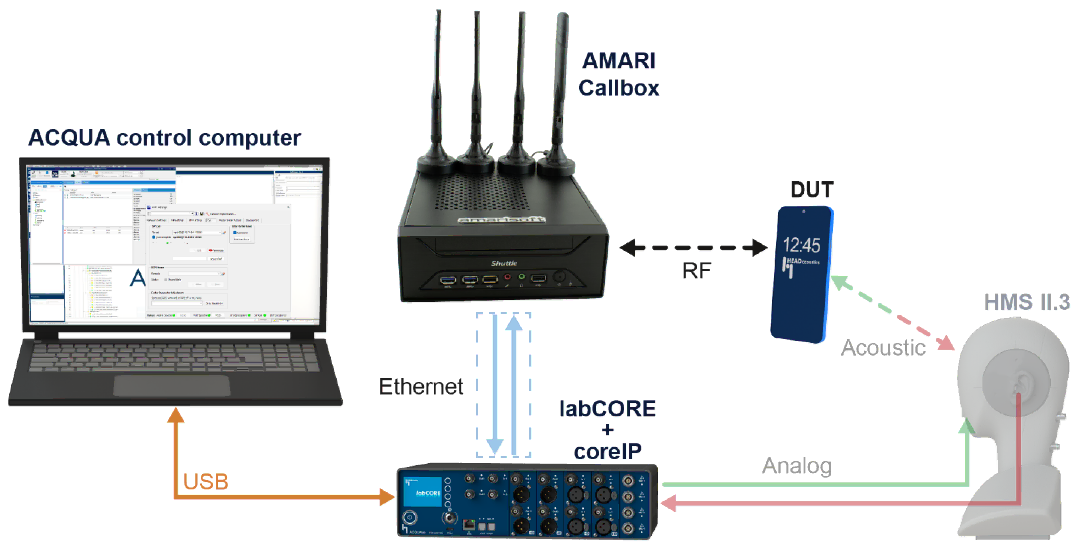
Test setup for this tutorial is as shown below.
This setup runs a Head Acoustics ACQUA test while the Amarisoft AMARI Callbox provides the cellular network.
- The ACQUA control computer is the main controller. It controls labCORE + coreIP via USB. ACQUA indirectly controlls Amarisoft via labCORE
- ACQUA controls labCORE via USB and labCORE then controls the AMARI Callbox over Ethernet, so the DUT is tested through the Callbox RF link while audio is routed through labCORE to the HMS II.3.
- The AMARI Callbox provides the RF link, RAN and core network software stack. It also support IMS core to the DUT. The DUT connects to the Callbox over the air, like a normal cellular call.
- The audio path is handled by HMS II.3 and labCORE. The DUT is placed in front of HMS II.3 for acoustic coupling. HMS II.3 is connected to labCORE with analog audio lines.
- labCORE works as the analog audio interface. It routes playback and recording signals between HMS II.3 and the ACQUA test application.
As a result, the test measures RF behavior and acoustic audio performance in one loop.
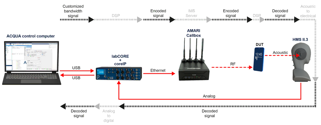
Data/Signal Flow - Recieve Path
This diagram shows the receive path data flow from the network side to the acoustic measurement side.
- A customized baseband signal is generated and processed in the DSP domain.
- This signal is converted into an encoded signal and delivered to the AMARI Callbox through the Ethernet-connected control chain via labCORE.
- The AMARI Callbox transmits the encoded signal over RF to the DUT.
- The DUT receives the RF signal and produces audio at the speaker, so the signal becomes an acoustic wave.
- HMS II.3 captures this acoustic output and converts it into an electrical analog signal.
- That analog signal is fed back to labCORE, where it is digitized and decoded.
- The decoded receive signal is then transferred to the ACQUA control computer over USB for logging, analysis, and scoring.
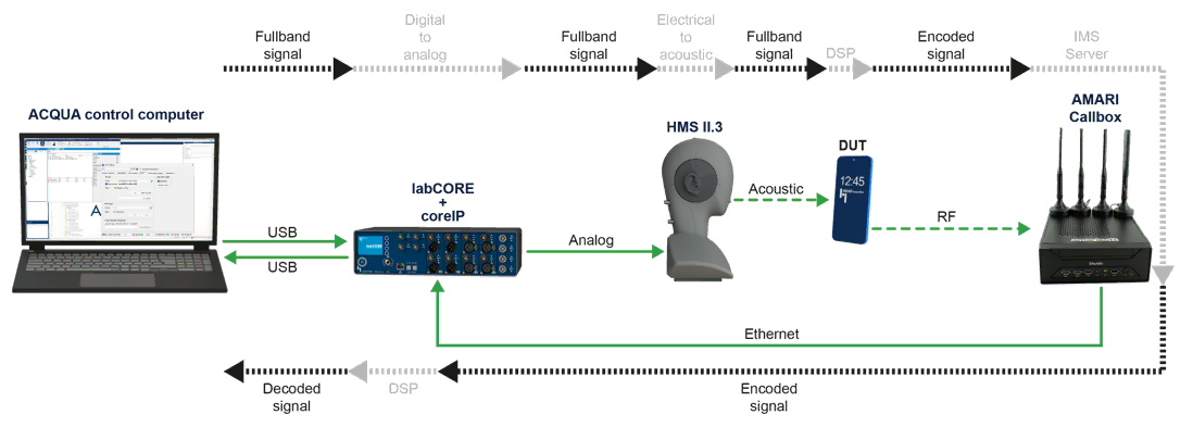
Data/Signal Flow - Send Path
This diagram shows the send path data flow from the acoustic injection side to the network side.
- ACQUA generates a fullband reference signal in the digital domain. This signal is sent to labCORE over USB.
- labCORE converts the digital signal to an analog electrical signal.That analog signal is fed into HMS II.3.
- HMS II.3 converts the electrical signal into an acoustic signal at the mouth position.
- The DUT picks up this acoustic signal at its microphone, so it becomes the DUT’s uplink audio.
- The DUT encodes the uplink audio and sends it over RF to the AMARI Callbox.
- The Callbox receives the RF uplink and outputs the encoded signal toward the IMS server side.
- In parallel, labCORE maintains the Ethernet link to the Callbox so the call context and routing stay consistent during the test.
Amarisoft Setup
This procedure show the network configuration steps on the Amarisoft Callbox that are needed before integrating it with HeadAcoustics. The key goal is to give the Callbox a fixed, predictable IP address instead of relying on DHCP, because HeadAcoustics will later need a stable target address to connect to and control the system.
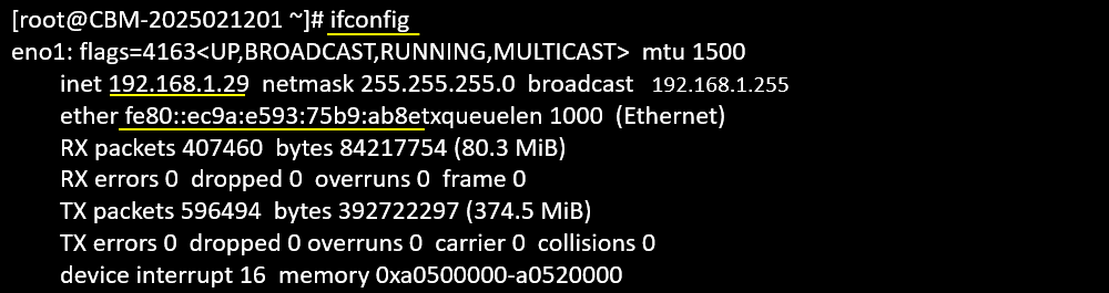
This ifconfig output confirms that the Callbox is using the eno1 Ethernet interface and that the interface is already UP and actively passing traffic. The important part for the HeadAcoustics setup is the IPv4 line, which shows the current address as 192.168.1.29 with a /24 mask (255.255.255.0). This is the IP you want to keep consistent by writing it into the persistent ifcfg-eno1 file, so HeadAcoustics can later point to a stable address instead of chasing a DHCP-assigned one.
This step moves into the directory where RHEL/CentOS-style systems keep the persistent network interface profiles. By changing to /etc/sysconfig/network-scripts, you are going to the place where files like ifcfg-eno1 are stored
![]()
Here you open a new (or template) interface configuration file using nano. The filename ifcfg-example is just a working draft, so you can paste or type the standard parameters for a static interface without immediately touching the real ifcfg-eno1 file.
![]()
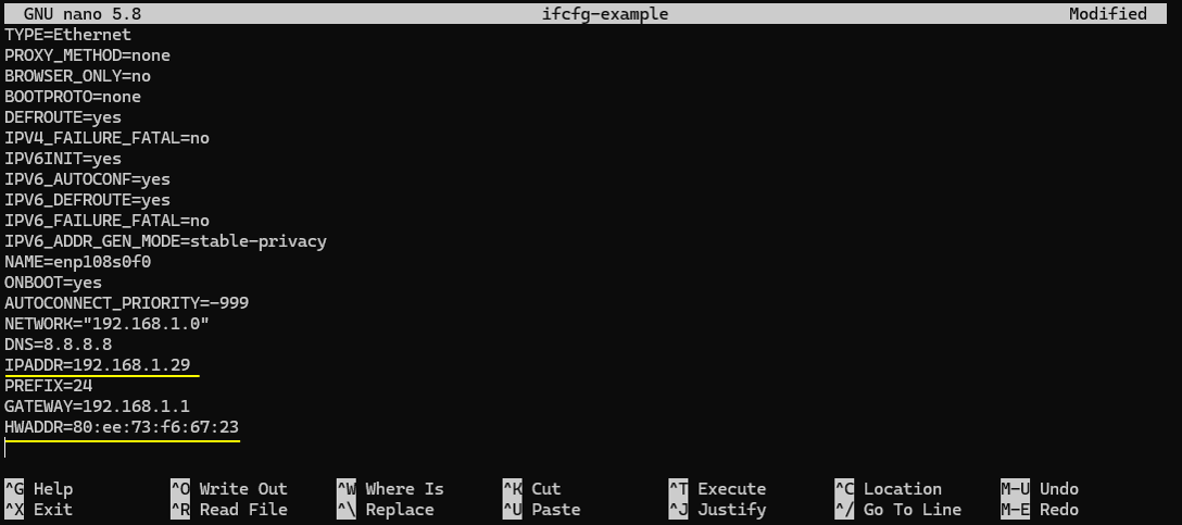
This is the actual static IP profile you are preparing for the Callbox interface. The key point is that BOOTPROTO=none disables DHCP, and ONBOOT=yes makes sure the interface comes up automatically after reboot. Then the fixed network identity is defined by IPADDR=192.168.1.29 with PREFIX=24, which means the Callbox will always use 192.168.1.29 on the 192.168.1.0/24 subnet. GATEWAY=192.168.1.1 sets the default route so the Callbox can reach outside its local subnet, and DNS=8.8.8.8 defines a resolver if name lookups are needed. HWADDR=80:ee:73:f6:67:23 ties this profile to a specific physical NIC, which helps avoid the wrong configuration being applied if interface naming changes or if multiple NICs exist. With these values in place (and saved later as ifcfg-eno1), HeadAcoustics can reliably connect to the Callbox using the same IP every time, without needing to rediscover the address.
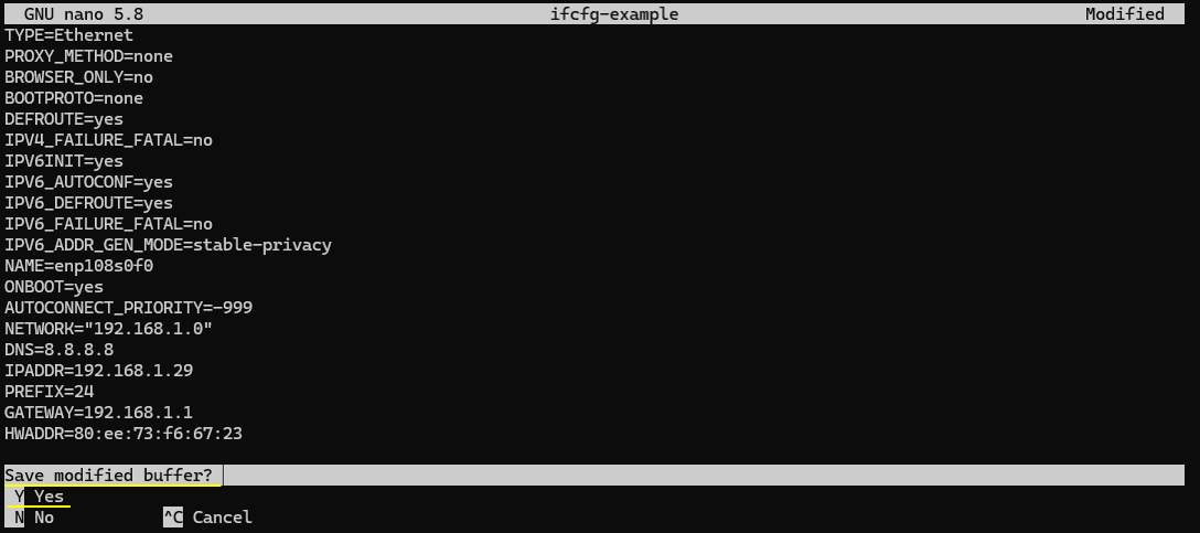
Select Yes, because the whole point is to save the fixed IP configuration so it can be applied later (and then typically you save it under the real interface file name like ifcfg-eno1)
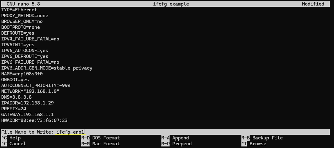
Nano is now asking what filename it should write the buffer to. Instead of saving it as the temporary name ifcfg-example, you overwrite the target name to ifcfg-eno1, which is the real configuration file that the system will load for the eno1 interface at boot. By saving it under ifcfg-eno1, you make the static IP settings official and persistent for that interface. After this, when the network service (or NetworkManager, depending on the system) brings up eno1, it will use the fixed values you entered (IPADDR, PREFIX, GATEWAY, etc.), which is exactly what you need so HeadAcoustics can always find the Callbox at the same address.
HeadAcoustics Setup
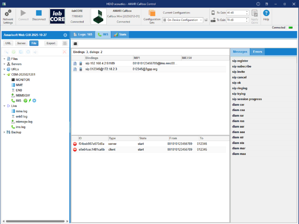
This screen shows the overall layout of Head acoustics AMARI Callbox Control. The top bar provides connection and control functions. It shows that labCORE and the AMARI Callbox are connected. It also shows configuration selection and RF gain controls.
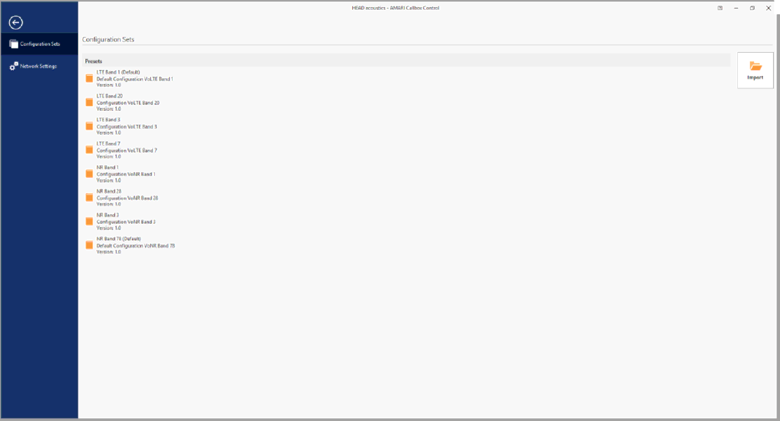
This screen shows the Configuration Sets page in Head acoustics AMARI Callbox Control. The left side has a vertical navigation bar. It provides two main entries. One is Configuration Sets. The other is Network Settings.
The main area shows a list of preset configuration folders. Each preset represents a ready-to-use Callbox setup. On the right side, there is an Import button with a folder icon. This is used to bring in an external configuration set file. This allows you to load a prepared Callbox profile and reuse it without manual editing.
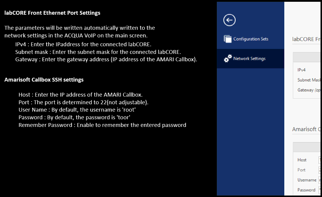
This screen explains the network and SSH parameters that Head acoustics will store for later use. The labCORE Front Ethernet Port Settings section defines the IPv4 information for the connected labCORE device. You enter the labCORE IP address and subnet mask here. You also enter the gateway address. The gateway is the AMARI Callbox IP address. These values are then written into the ACQUA VoIP network settings automatically.
The Amarisoft Callbox SSH settings section defines how the tool logs into the Callbox. The Host field is the Callbox IP address. The SSH port is fixed to 22, so it is not adjustable. The default username is root. The default password is toor. There is also an option to remember the entered password so you do not need to retype it each time.
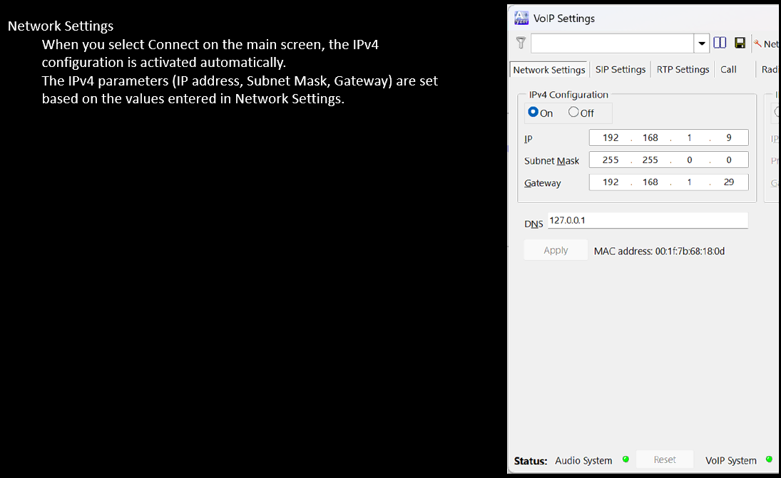
This screen explains how the IPv4 settings are applied in the VoIP tool. When you press Connect on the main screen, the IPv4 configuration is turned on automatically. The tool then fills in the IPv4 fields using the values you previously entered in the Network Settings page. On the right, the VoIP Settings window shows the Network Settings tab. IPv4 Configuration is set to On. The IP address is set to 192.168.1.9 for the labCORE side. The subnet mask is set to 255.255.0.0. The gateway is set to 192.168.1.29, which matches the AMARI Callbox fixed IP you configured earlier. This means labCORE traffic can route through the Callbox without manual re-entry each time you connect.
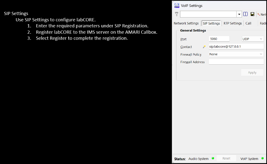
This screen describes how you set up SIP so labCORE can work with the IMS on the AMARI Callbox. You use the SIP Settings tab in the VoIP Settings window. You enter the required values in the SIP registration area. Then you register labCORE to the IMS server running on the Callbox. After you press Register, the registration procedure completes and labCORE becomes a SIP endpoint.
On the right, the SIP Settings tab is open and it shows the basic General Settings. The SIP port is set to 5060 and the transport is UDP. The Contact field is set to something like sip:labcore@127.0.0.1, which defines the SIP identity used by the tool. Firewall policy is set to None, so it is not applying extra NAT/firewall handling from this page. The Apply button is used to store the entered SIP parameters before you run the registration step.
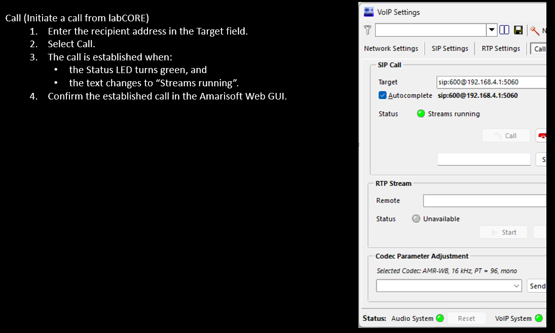
This screen describes the call initiation step from labCORE. You start from the VoIP Settings window and open the Call tab. You enter the recipient SIP URI into the Target field. In this example, the target is sip:600@192.168.4.1:5060, so labCORE will place a SIP call to user 600 on the remote IP and port.
After you enter the target, you select Call. The call is considered established when the status indicator turns green and the status text changes to Streams running. This is the practical confirmation that SIP signaling has completed and the media stream is active from the labCORE side. Then you confirm the same call state on the Amarisoft side using the Amarisoft Web GUI, so you can verify that the IMS/Callbox also sees the dialog and media as expected.
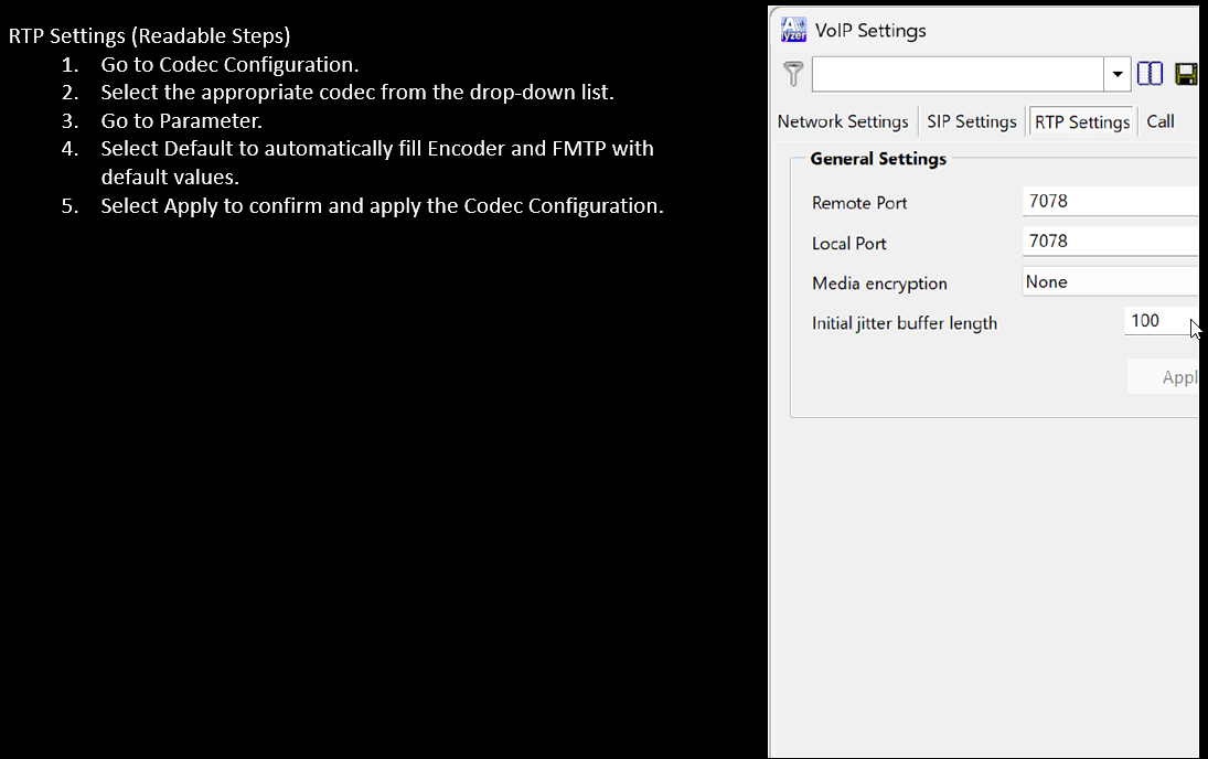
This screen shows the RTP configuration area used for VoIP media setup. The flow starts from codec configuration. You move to the codec selection menu and choose the codec that matches your test requirement. Then you move to the parameter section. If you select Default, the tool automatically fills the encoder and FMTP fields with the standard values for the chosen codec. After that you press Apply so the codec and RTP parameter changes are stored and activated.
On the right, the RTP Settings tab is open and it shows the basic transport parameters. Both Remote Port and Local Port are set to 7078, so the RTP stream is expected to use that UDP port on each side. Media encryption is set to None, so the RTP payload is not encrypted at this stage. The Initial jitter buffer length is set to 100, which defines how much buffering the receiver uses to absorb packet jitter before playing out the audio.
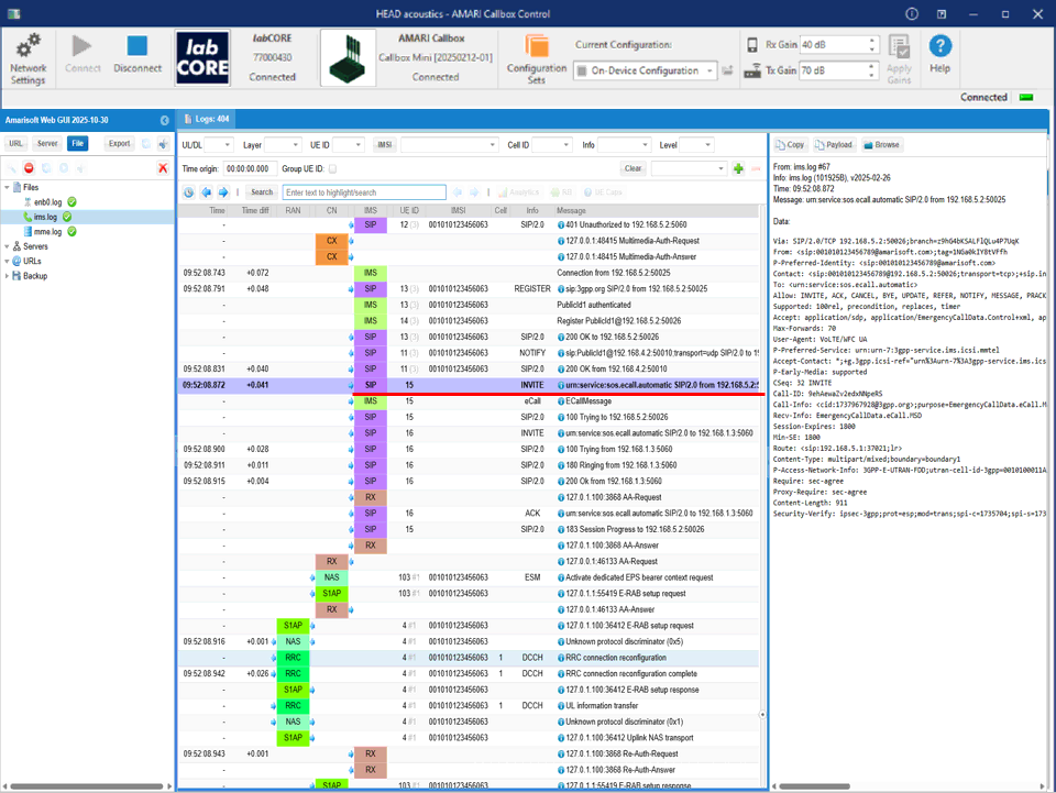
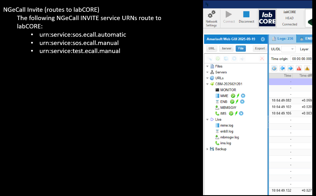
This screen explains how an NGeCall INVITE can be routed to labCORE using specific service URNs. The left text lists the URNs that the system treats as routable to labCORE. These include urn:service:sos.ecall.automatic, urn:service:sos.ecall.manual, and urn:service:test.ecall.manual. When an INVITE contains one of these service URNs, the Callbox/IMS side uses it as a routing indicator and forwards the call toward the labCORE endpoint instead of treating it as a normal public user dial.
ECallMessage shows the time context and then a structured Data block. That block contains the eCall payload fields, such as version and an identifier/value string, which confirms that the Callbox recognized the incoming eCall content and parsed it into a dedicated eCall message object. In other words, it shows the exact moment in the SIP call flow where the system detects and exposes the eCall application information, so you can verify that the eCall INVITE is being routed and interpreted correctly by the IMS on the AMARI Callbox.
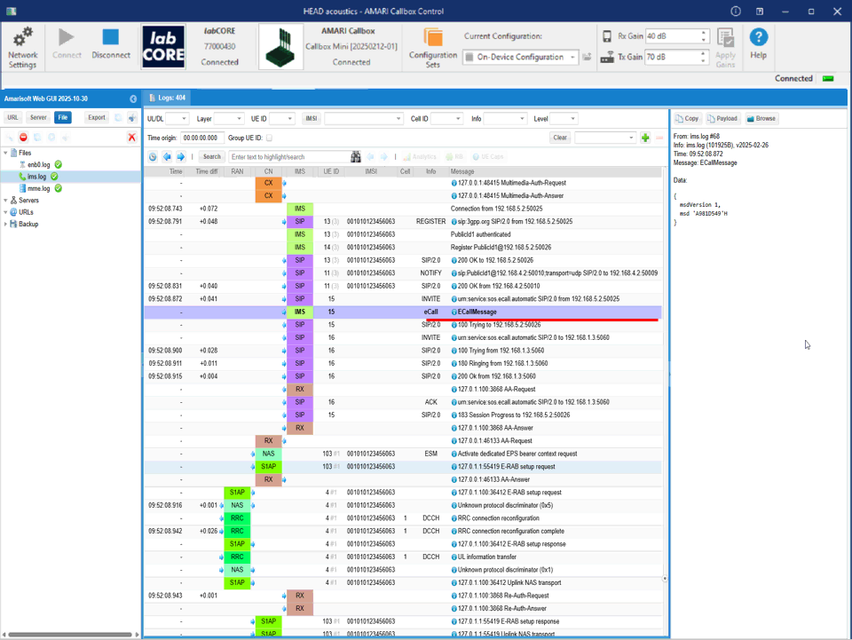
This shows SIP INVITE that triggers the eCall session. In the middle event list, the selected row is an IMS / SIP entry with method INVITE. The Info field shows the eCall service URN, so this INVITE is treated as an NGeCall request rather than a normal VoIP call. The row immediately below it shows ECallMessage, which indicates that the Callbox decoded eCall application data associated with this INVITE.
The right-hand pane shows the full SIP message for the highlighted INVITE. You can see it is an emergency-style call setup because the headers include things like Accept-Contact with +g.3gpp.icsi-ref and service indicators, and the Request-URI is the eCall service URN. The header also contains a Call-Info entry that points to an eCall XML body, and the payload section shows the MIME structure for the eCall content. This is the key confirmation point: the INVITE is not only routed to the IMS, but it also carries the eCall-specific body, and Amarisoft exposes it both as a SIP transaction (INVITE/100 Trying/180 Ringing/200 OK) and as a decoded ECallMessage event in the log list.