Running Multiple eNB
The purpose of this tutorial is to show you how to run multiple MME and let multiple eNB get connected to different MME.
(
Introduction
In modern LTE (Long Term Evolution) network environments, the ability to deploy and manage multiple Mobility Management Entities (MMEs) alongside multiple evolved NodeBs (eNBs) is crucial for scaling, redundancy, and advanced testing scenarios. The MME serves as the core component responsible for handling signaling related to mobility and security for user equipment (UE) within the Evolved Packet Core (EPC), while eNBs act as the radio access nodes providing wireless connectivity to UEs. This tutorial delves into the technical process of executing multiple instances of MMEs and eNBs on a single LTE service platform, an approach typically employed in laboratory or pre-production test setups. Architecturally, each MME instance operates as a distinct logical entity, maintaining separate signaling and session states, and can be selectively associated with different eNBs to emulate real-world multi-core network deployments. This setup enables comprehensive validation of network component interoperability, failover mechanisms, and load distribution strategies. The significance of mastering this configuration lies in its direct applicability to scenarios such as network slicing, high-availability testing, and performance benchmarking. It also requires careful configuration management, precise allocation of licenses, and an in-depth understanding of LTE core network components, their configuration files, and inter-component signaling flows. By following this tutorial, engineers and network professionals will gain practical expertise in orchestrating a multi-MME, multi-eNB LTE testbed, facilitating advanced experimentation and robust validation of next-generation mobile core architectures within a controlled environment.
-
Context and Background
- LTE networks comprise multiple interconnected core and access network elements, with MMEs and eNBs serving as pivotal components for signaling and radio access management.
- Running multiple MMEs allows simulation of geographically or logically distributed core networks, enhancing both scalability and fault tolerance.
- Associating different eNBs to distinct MMEs emulates real-world operator deployments and enables rigorous testing of handover, registration, and session management scenarios.
-
Relevance and Importance of Tutorial Topic
- Understanding the configuration and operational aspects of multiple MMEs and eNBs is vital for telecom engineers tasked with designing, testing, or optimizing LTE networks.
- The ability to execute multiple network components on a single service platform maximizes resource utilization and accelerates the prototyping and validation of new features or architectures.
- This tutorial addresses practical challenges such as license management, configuration file setup, and troubleshooting complex signaling interactions.
-
What Learners Will Gain
- Step-by-step guidance on configuring and launching multiple MMEs and eNBs within a unified LTE service environment.
- Hands-on experience with configuration files and parameterization for each network component (eNB0, eNB1, MME0, MME1, IMS0, IMS1, OTS).
- Proficiency in conducting integrated tests, monitoring system logs, and analyzing signaling flows for multi-component LTE networks.
- Enhanced troubleshooting skills and the ability to interpret log data for complex, multi-entity scenarios.
-
Prerequisite Knowledge and Skills
- Familiarity with LTE/EPC architecture, including the roles and interactions of MMEs, eNBs, IMS (IP Multimedia Subsystem), and OTS (Other Test Systems).
- Experience with Linux-based environments and command-line interfaces for managing network services and configurations.
- Basic understanding of network protocols such as S1-AP, GTP, and Diameter, as well as the practical aspects of system licensing and resource allocation.
- Access to required license files for running multiple components, as each additional MME or eNB instance typically mandates dedicated licensing.
Summary of the Tutorial
This test involves configuring and launching two instances of eNB, MME, and IMS components within a callbox environment using the LTE service. The procedure focuses on verifying the multi-instance setup and ensuring correct operation and interconnection of all network elements.
-
Configuration Setup:
- Copy and modify configuration files for each component:
- eNB: enb.default0.cfg and enb.default1.cfg (from enb.default.cfg), symbolically linked as enb0.cfg and enb1.cfg.
- MME: mme-ims-2enb-0.cfg and mme-ims-2enb-1.cfg (from mme-ims.cfg), symbolically linked as mme0.cfg and mme1.cfg. MME1 is configured for PLMN 00102 and uses a different gtp_addr than MME0.
- IMS: ims.default0.cfg and ims.default1.cfg (from ims.default.cfg), symbolically linked as ims0.cfg and ims1.cfg.
- OTS: ots-2enb-2mme.cfg (from ots.default.cfg).
- Apply specific modifications to each configuration file as required for the test environment.
- Copy and modify configuration files for each component:
-
Test Execution:
- Start the LTE service, which automatically launches all configured instances (eNB0, eNB1, MME0, MME1, IMS0, IMS1) and adds them to the 'screen' session.
- No UE attach procedures are performed; only the network components are initiated and observed.
-
Verification Steps:
- Using the 'screen' interface, verify that new components (enb1, mme1, ims1) are active as per the OTS configuration.
- Check the network interfaces while the LTE service is running:
- Confirm creation of multiple tun interfaces as per MME configurations.
- Review IPv4 and IPv6 routing tables generated by the operating system and LTE service.
- Within the LTE service screen, perform the following checks:
- Review cell configuration and S1 connectivity for ENB0 and ENB1.
- On MME0 and MME1, confirm connections to the appropriate eNB and IMS instances.
- On IMS0 and IMS1, confirm connections to the respective MME instance.
-
Log Analysis:
- Access the WebGUI to verify the presence of new components (ENB1, MME1, IMS1).
- Review highlighted log steps for successful initialization and inter-component connectivity.
This test validates the ability to run multiple, independently configured core LTE components within a single environment, ensuring proper configuration, initialization, and connectivity without performing UE attach operations.
Test Setup
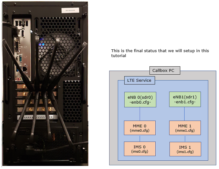
In this setup, two instances of eNB/MME/IMS are running in the callbox. All the components will launch automatically by lte service and all the components will be automatically added to 'screen' window as well.
Configuration
Configuration File Setup
I used enb.default0.cfg and enb.default1.cfg which are copied from enb.default.cfg (These configuration files are located in /root/enb/config). Note that enb0.cfg and enb1.cfg are symbolically linked to enb.default.0.cfg and enb.default1.cfg respectively. (These configuration files are located in /root/mme/config).

I used two separate mme configuration files : mme-ims-2enb-0.cfg and mme-ims-2enb-1.cfg which are copied and modified from mme-ims.cfg. Note that mme0.cfg and mme1.cfg are symbolically linked to mme-ims-enb-0.cfg and mme-ims-enb-1.cfg respectively. (These configuration files are located in /root/mme/config).

I used two separate ims configuration files : mme.default.0.cfg and mme.default1.cfg which are copied and modified from ims.default.cfg. Note that ims0.cfg and ims1.cfg are symbolically linked to ims.default0.cfg and ims.default1.cfg respectively. (These configuration files are located in /root/mme/config).

I used ots-2enb-2mme.cfg which is copied and modiefied from ots.default.cfg (These configuration files are located in /root/ots/config).

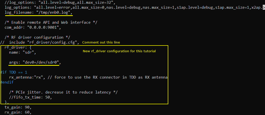
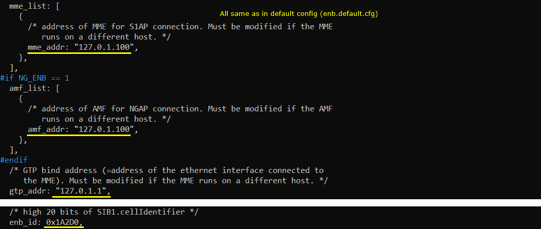
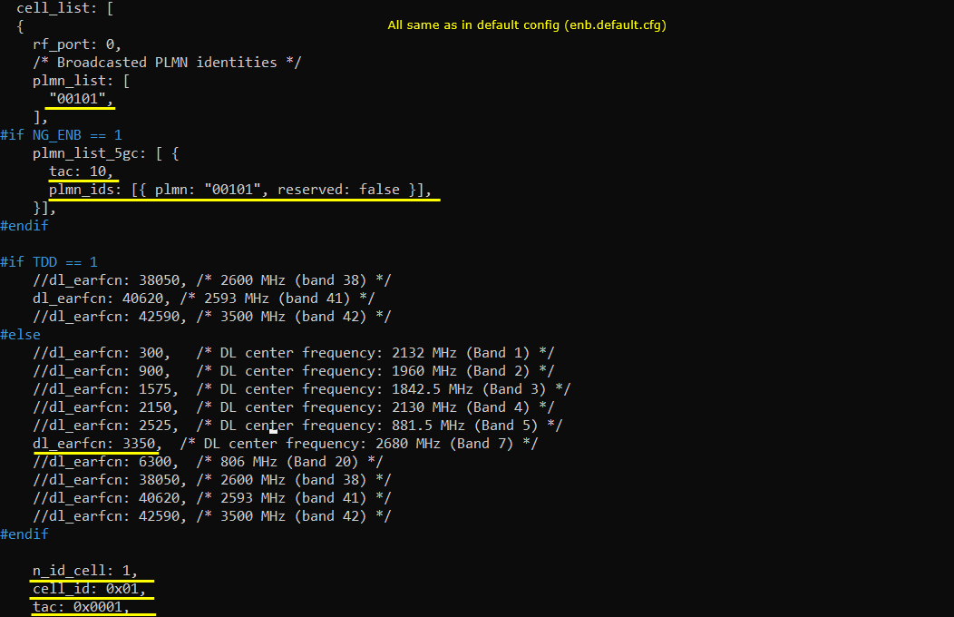
Configuration for eNB 0
In enb.default0.cfg , I made modifications as follows. Note that this is exactly same as enb.default.cfg.

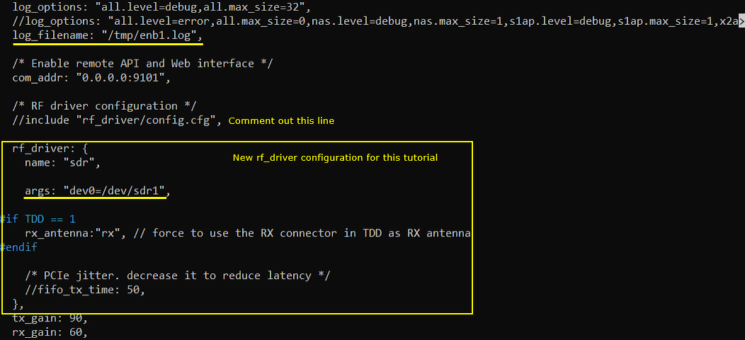
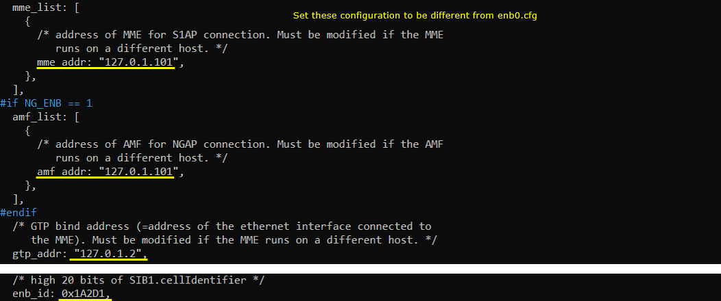
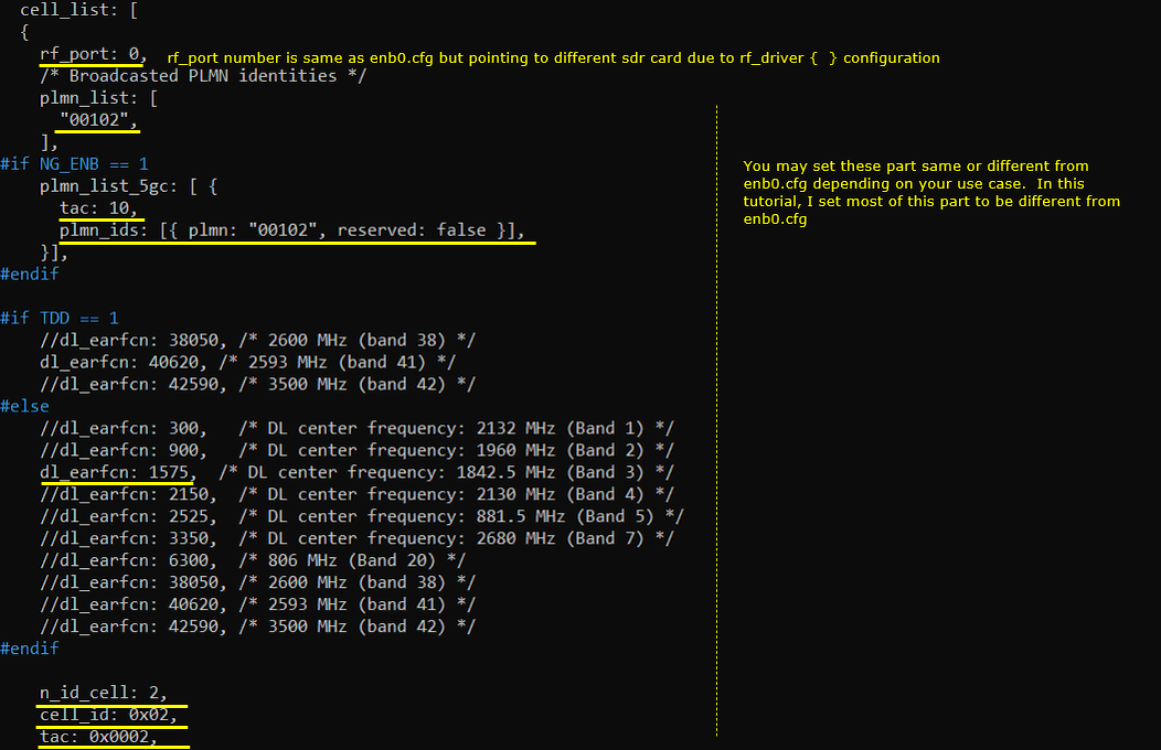
Configuration for eNB 1
In enb.default1.cfg , I made modifications as follows. Note that this is exactly same as enb.default.cfg.

Configuration for MME 0
Followings are the configuration in mme.default.0.cfg


Configuration for MME 1
Followings are the configuration in mme.default.1.cfg. NOTE that this MME has configured for the PLMN 00102 and use the gtp_addr which is different from MME 0.


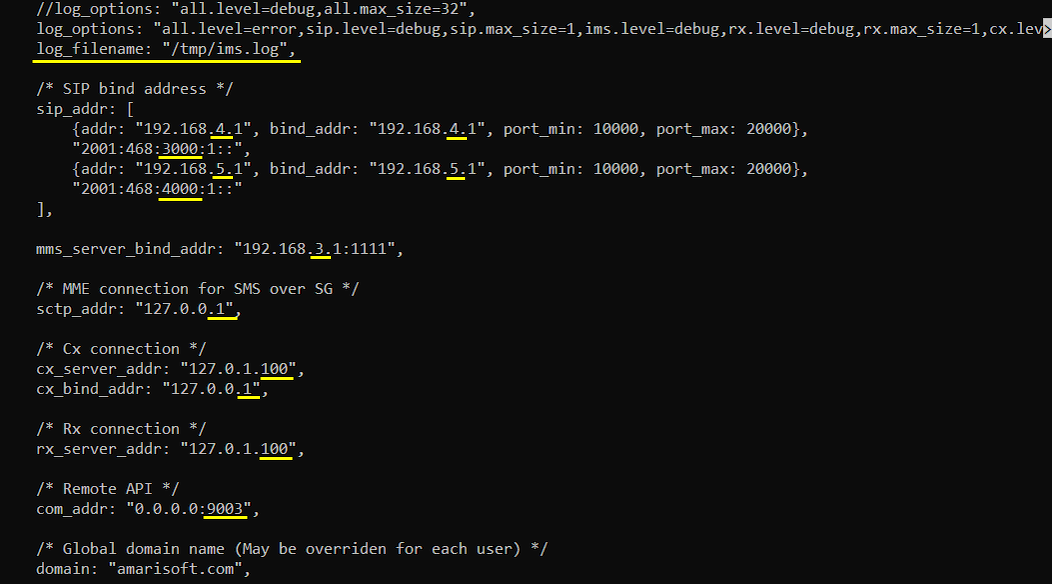
Configuration for IMS 0
Followings are the configuration in ims.default0.cfg
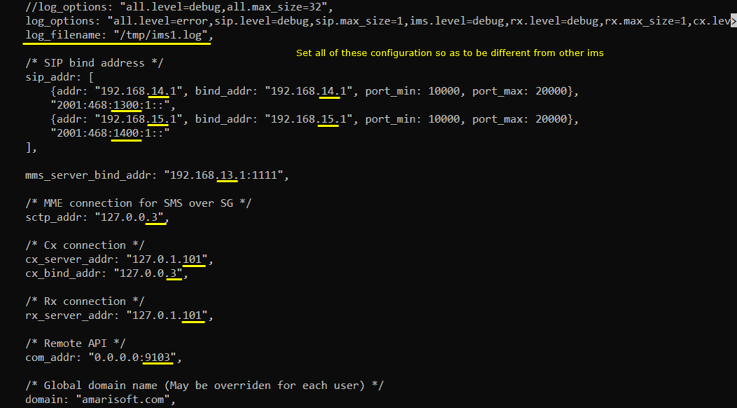
Configuration for IMS 1
Followings are the configuration in ims.default1.cfg
Configuration for OTS
Followings are the configuration in ots-2enb-2mme.cfg


Perform the test
In this test, I would just run a lte service with additional enb, mme and ims. I would not try any UE attach. In this test, all the eNB,mme and ims are run automtically by lte service.
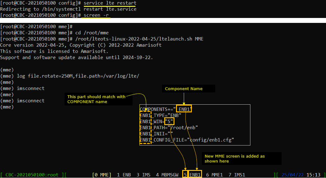
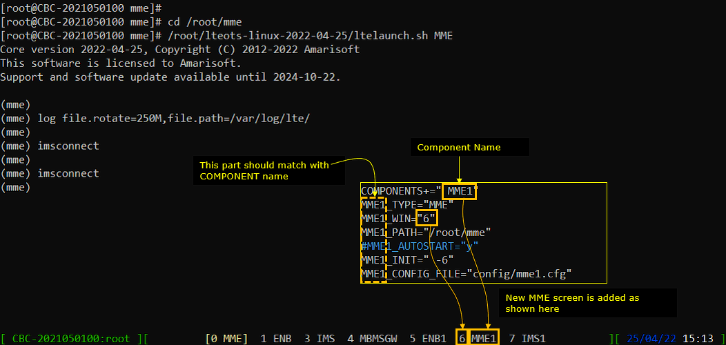
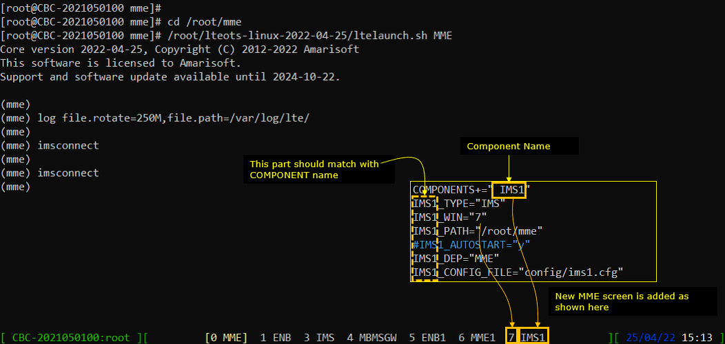
If you run lte service and get into screen mode, you will see a new components (enb1,mme1,ims1) are added as below. This addition is done by the configuration in ots.cfg as indicated below.
Now check out the network interface while the service is running and you will see many tun interfaces are created as shown below.
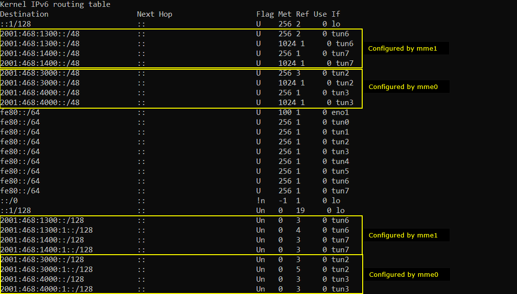
these are the tun interface created by mme0.cfg
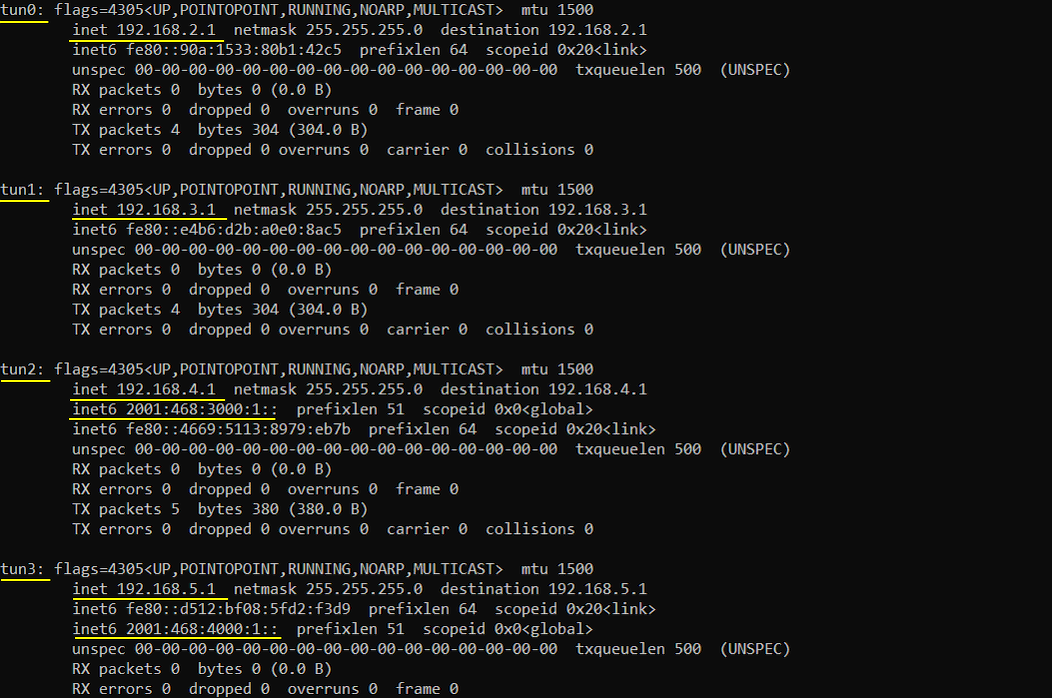
these are the tun interface created by mme1.cfg
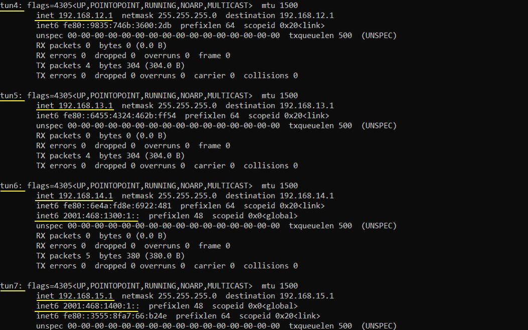
Followings are the ipv4 routing table created by the operating system and lte service.

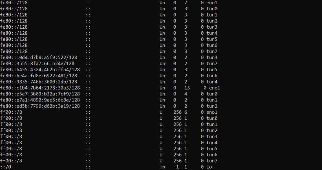
Followings are the ipv6 routing table created by the operating system and lte service.
Now go back to lte service screen and check follows.
Check on the cell configuration of ENB0 as shown below.

Check on the mme (s1) that is connected to ENB0

Check on the cell configuration of ENB1 as shown below.

Check on the mme (s1) that is connected to ENB1

Go to MME (mme0) and check out the connected enb.

Go to MME (mme0) and check out the connected ims.

Go to MME (mme1) and check out the connected enb.

Go to MME (mme1) and check out the connected ims.

Go to MME (ims0) and check out the connected mme.

Go to MME (ims1) and check out the connected mme.

Log Analysis
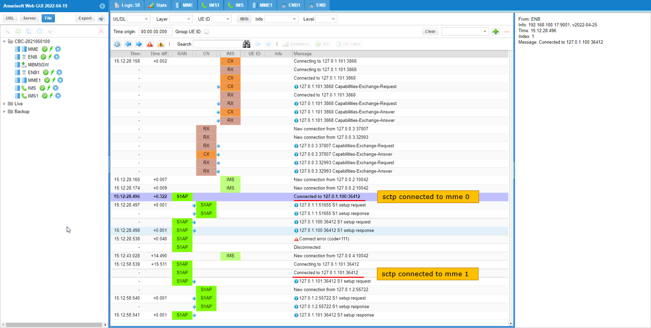
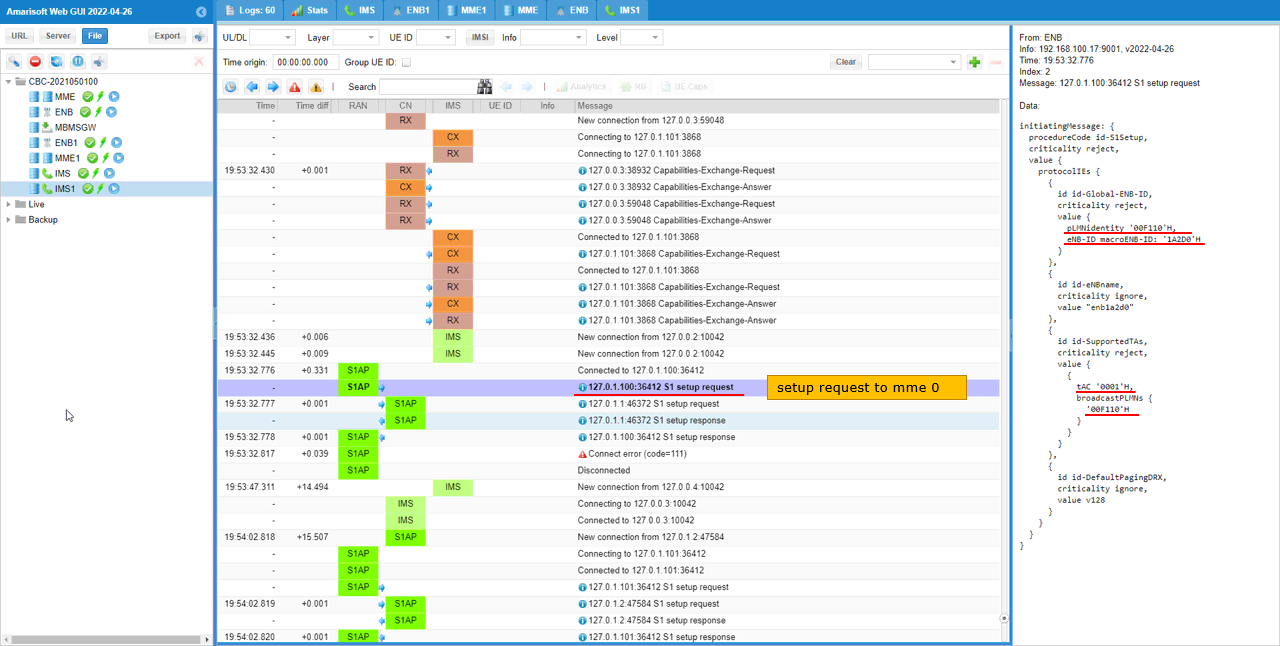
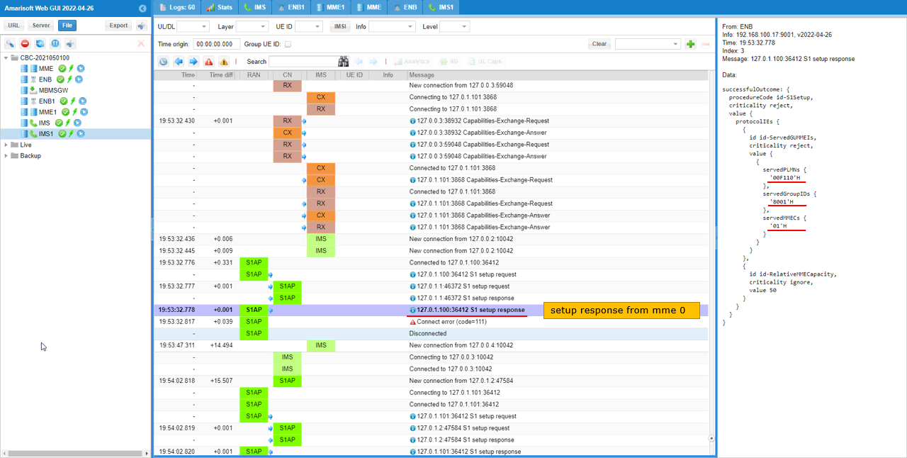
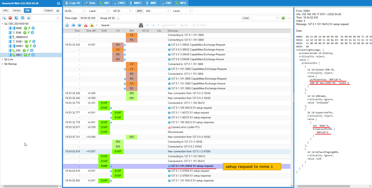
If you run WebGUI, you would notice that a new components (ENB1,MME1,IMS1) are added as shown below.
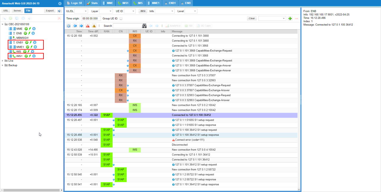
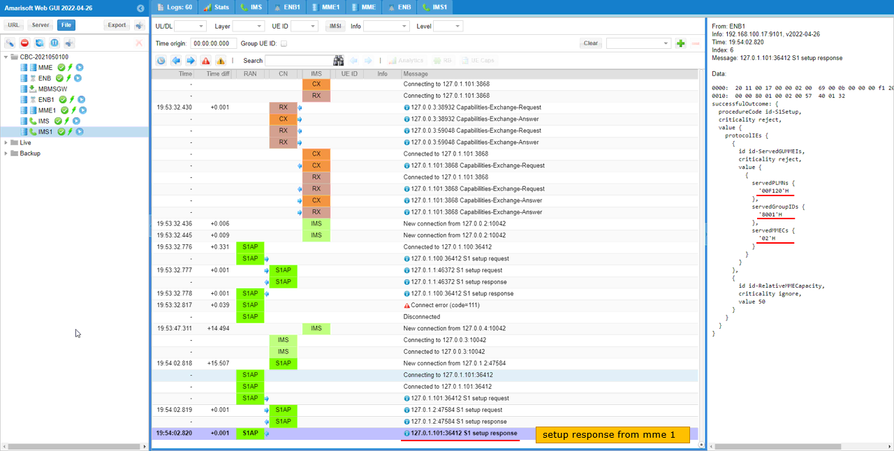
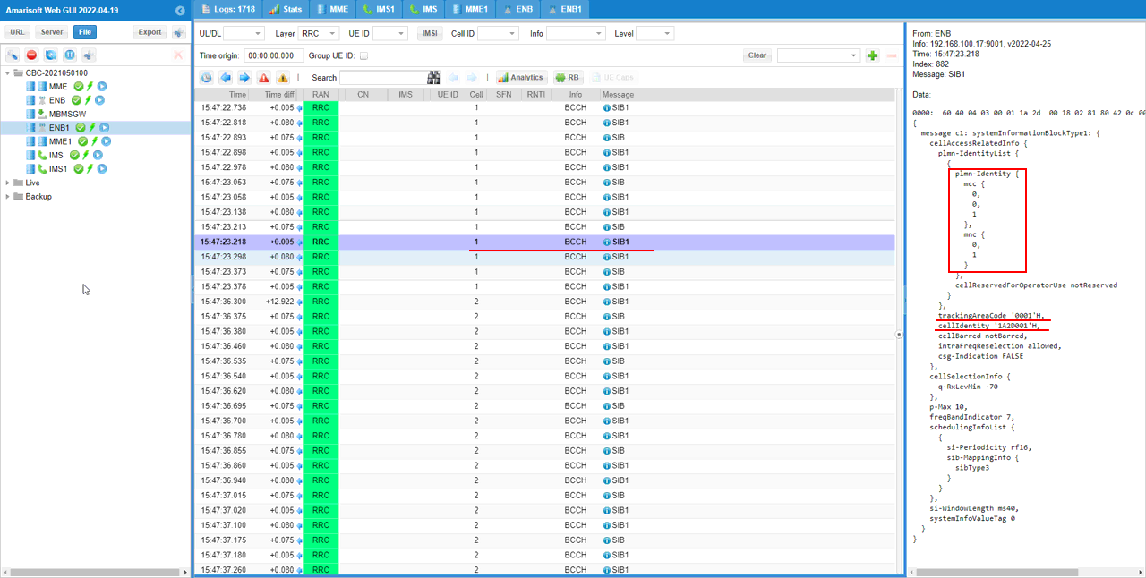
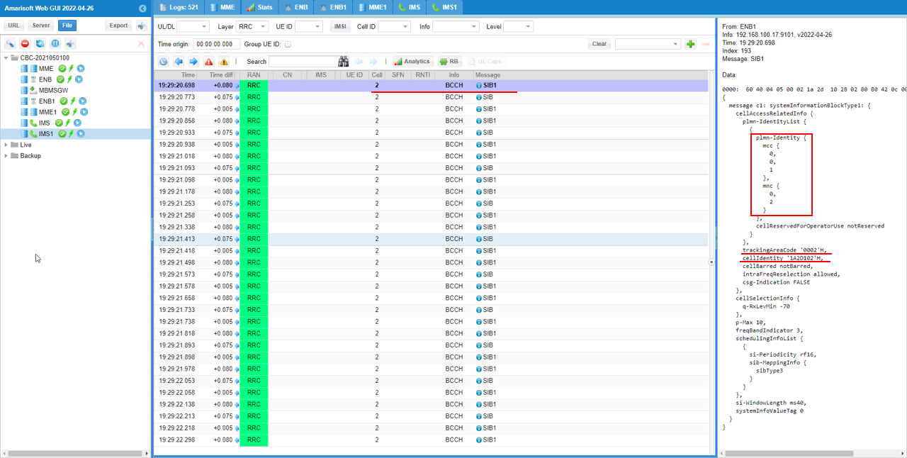
Followings are some of highlighted steps you may want to check.
