Amarisoft

Amarisoft gNB + Open5GS on Cloud

The purpose of this tutorial is to show you how to setup an opensource 5G Core called Open5GS on a local Virtual Machine and how to use it as a whole or in combination with Amarisoft Core (mme).

The purpose of this tutorial is to show you how to setup a non-Amarisoft Core (Open5GS) on Google Cloud Virtual Machine and configure Callbox (gNB) connected to the 5G Core on Cloud.  The purpose of this tutorial is to show a sample case where a non-Amarisoft Core is installed on a cloud which is located far away from RAN. This kind of the setup would introduce some factors that does not come into play in regular setup where RAN and Core are installed on the same PC. Those factors are as follows : My motivation was to check if all of these factors (challenges) are properly handled and overcome.

NOTE :  The factors listed above may vary with the type of the cloud you use and another non-amarisoft component Open5GS. Even if you are using the same cloud  and Open5GS as this tutorial, you may come across different problems / challenges by the time you are trying this. This tutorial is just to show a proof of concept for application of Cloud and Open5GS and we will not follow up /nor provide any technical support for the non-Amarisoft components.

Table of Contents

Introduction

The rapid evolution of 5G technology has driven the need for flexible and scalable mobile network architectures. Open5GS is a prominent open-source implementation of 5G core network functions, providing a modular and compliant platform for both research and commercial deployments. This tutorial focuses on deploying Open5GS on a cloud-based Virtual Machine (VM), specifically on Google Cloud, and configuring connectivity with a remote Radio Access Network (RAN) Amarisoft Callbox(gNB), situated hundreds of kilometers away. Unlike traditional setups where the 5G Core and RAN reside on the same physical machine or local network, this distributed architecture introduces unique challenges, including significant data-plane and control-plane latency, complex Network Address Translation (NAT) scenarios, and stringent firewall configurations. The Open5GS core, comprising modular network functions such as AMF, SMF, UPF, and others, communicates with the RAN over standardized 3GPP interfaces (e.g., NGAP over SCTP), making interoperability and network configuration critical for successful deployment. The significance of this architecture lies in its ability to demonstrate real-world cloud-native 5G core deployments, reflecting modern carrier network trends where core and RAN are often geographically and logically separated. This tutorial offers a practical, step-by-step guide to setting up Open5GS in the cloud, addressing the technical hurdles encountered when integrating with remote RAN equipment and highlighting the role of cloud infrastructure in next-generation mobile networks.

Summary of the Tutorial

This tutorial outlines the test setup and procedures for validating interoperability between Amarisoft gNB and Open5GS as the 5G core network in a cloud-based environment. The test leverages Amarisoft UEsim as a test UE, focusing on configuration flexibility and compatibility with Open5GS network slicing.

Note: The tutorial assumes familiarity with basic VM setup, Open5GS installation, and Amarisoft configuration procedures. Configuration details unique to other test scenarios (if applicable) would be specified under their respective sections.

Test Setup

Test setup for this tutorial is as shown below.  I assume that you would know on how to setup the Virtual Machine and run an instances of operating system (Ubuntu in this tutorial) and I would not explain on the procedure of those installation procedure.
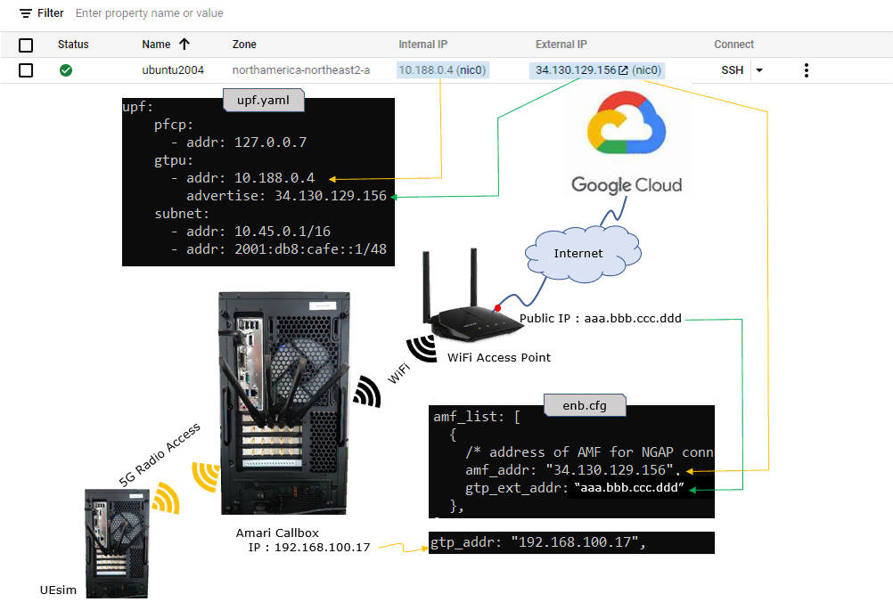
NOTE : In this tutorial, I used Amarisoft UEsim as a Test UE instead of commercial UE. The main reason is becaue Open5GS does not support 3GPP Test USIM algorithm (XOR) and (as far as I have observed) Network Slicing configuration doesn't seem to be very flexible (so I need a test UE in which I can change Network Slicing Configuration as it can be accepted by open5gs).

In this setup, Open5GS is installed on a Google Cloud VM, and the Amarisoft Callbox is located in the local home network. The cloud VM has both an internal IP and an external public IP. In this example, the internal IP of the VM is 10.188.0.4 and the external IP is 34.130.129.156.

On the Open5GS side, the UPF configuration needs to use the internal IP address for the GTP-U interface. In upf.yaml, the gtpu address is configured as 10.188.0.4. This is the IP address assigned to the VM network interface inside Google Cloud. However, since the Amarisoft gNB is outside the Google Cloud network, the UPF also needs to advertise the external public IP address. Therefore, advertise is configured as 34.130.129.156. This tells the gNB which public IP address should be used to reach the UPF from outside the cloud network.

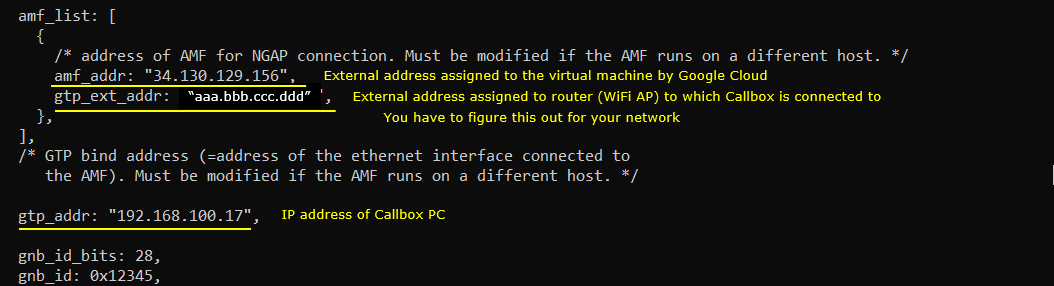
On the Amarisoft side, the gNB needs to know the AMF address for NGAP connection. In enb.cfg, amf_addr is configured as 34.130.129.156, which is the external public IP address of the Google Cloud VM. This allows the Amarisoft gNB to establish the NGAP SCTP connection to the AMF through the internet.

Since the Amarisoft Callbox is behind a home Wi-Fi router, its local IP address is 192.168.100.17, but this address is not directly reachable from the cloud. The home router translates this local IP into its public IP address. In this example, the public IP address of the home router is shown as aaa.bbb.ccc.ddd. Therefore, in enb.cfg, gtp_addr is configured as 192.168.100.17, which is the local IP address of the Amarisoft Callbox, while gtp_ext_addr is configured as aaa.bbb.ccc.ddd, which is the public IP address seen from the cloud side.

With this configuration, the control-plane connection is established from the Amarisoft gNB to the AMF using the cloud external IP address. For the user plane, Open5GS UPF uses its internal GTP-U address but advertises its cloud external IP address to the gNB. On the opposite side, the Amarisoft gNB uses its local GTP-U address but advertises the home-router public IP address so that the UPF can send GTP-U packets back through the internet.

NOTE : By the time when you try this, the user interface that you see on google cloud may not be the same as shown here since GUI is subject to change frequently. But the overall logic explained here would still be applicable.

TestSetup Cloud Open5gs 01

Key Configuration Parameters

Followings are important configuration parameters for this tutorial. You may click on the items for the descriptions from Amarisoft documents.

Configuration

In this section, I will show the configurations for various components in the test setup that will be commonly used for every test cases in this tutorial.  The configurations that is specific to each test case will be described in the configuration section under each test case.

Cloud

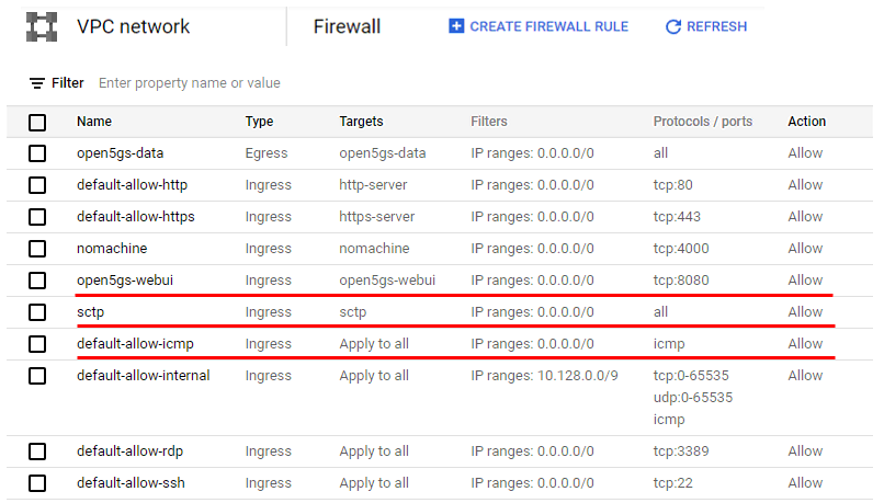
The first thing you need to configure is the cloud firewall. Since the Amarisoft Callbox is located at home or in the office and Open5GS is running on the cloud, the required signaling and user-plane traffic must be allowed to pass through the cloud firewall.

The following example shows the firewall rules used in my cloud setup. In addition to the default firewall rules, you should add at least the rules highlighted in red.

The open5gs-webui rule allows access to the Open5GS WebUI through TCP port 8080. This is required when you want to access the Open5GS subscriber database and other WebUI functions from a browser.

The sctp rule allows SCTP traffic between the Amarisoft gNB and the Open5GS AMF. This is one of the most important settings because NGAP signaling between gNB and AMF uses SCTP. If this rule is missing, the gNB cannot establish the NGAP connection to the AMF even if the AMF IP address is configured correctly.

The default-allow-icmp rule allows ICMP traffic. This is useful for basic connectivity testing, such as pinging the cloud VM from the Callbox side or checking whether the cloud VM is reachable from the local network.

Depending on your test setup, you may also need to allow additional traffic for the user plane, such as GTP-U, and for management access, such as SSH or remote desktop. The exact firewall rules may be different depending on your cloud provider and your security policy, but the key point is that the cloud firewall should not block the protocols required between the RAN and Core.

Cloud Open5gs Configuration Cloud 01

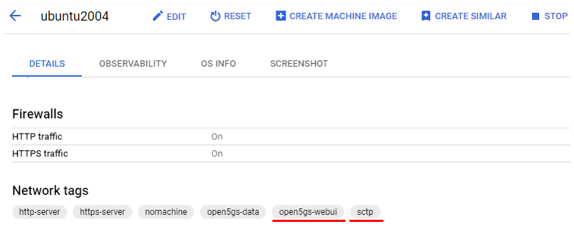
In Google Cloud, the firewall rule does not become active only by creating the rule. The corresponding network tag should also be assigned to the VM instance. In this example, the VM instance is ubuntu2004, and the required network tags are added under the Network tags section.

For this tutorial, the important tags are open5gs-webui and sctp. The open5gs-webui tag is used to allow access to the Open5GS WebUI through the firewall rule configured for TCP port 8080. The sctp tag is used to allow SCTP traffic for the NGAP connection between the Amarisoft gNB and the Open5GS AMF.

If these tags are not assigned to the VM, the firewall rules may not be applied to this instance, even though the firewall rules themselves are already created. Therefore, after creating the firewall rules, make sure that the same tags are added to the VM instance that is running Open5GS.

Cloud Open5gs Configuration Cloud 02

The OS information used in this tutorial is shown below. For Amarisoft MME alone, you may be able to use various Linux distributions. However, in this tutorial I used Ubuntu Server 20.04 because the same server is also used for Open5GS.

At the time of this test, Open5GS worked properly on Ubuntu Server 20.04. I also tried Ubuntu Server 22.04, but the installation did not go through. Ubuntu Desktop also did not work properly for Open5GS in my test setup. Because of this, Ubuntu Server 20.04 was selected as the baseline OS for this tutorial.

In this example, the OS version is Ubuntu 20.04.4 LTS, and the kernel version is 5.13.0-1027-gcp. This confirms that the Open5GS cloud server is running on Ubuntu Server 20.04 in Google Cloud.

Cloud mme Configuration Cloud 03

Open5GS

I assume that you know how to install open5gs and would not explain about the detailed installation procedure. If you are not familiar with open5gs installation procedure, refer to the QuickStart of Open5gs official site or a note in sharetechnote.

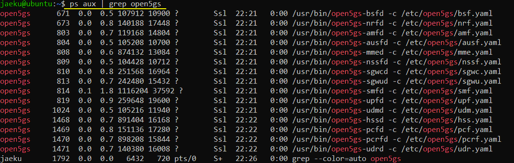
Once Open5GS is successfully installed on the virtual machine, you can check whether the Open5GS services are running by using the ps command.

In this example, the command ps aux | grep open5gs shows that all major Open5GS network functions are running. You can see processes such as open5gs-amfd, open5gs-ausfd, open5gs-smfd, open5gs-upfd, open5gs-nrfd, open5gs-pcfd, open5gs-udmd, and open5gs-udrd. Each process is started with its own configuration file under /etc/open5gs, such as amf.yaml, smf.yaml, upf.yaml, and so on.

This confirms that Open5GS has been installed and that the main 5G Core components are running on the cloud VM. At this point, the next step is to modify the required configuration files so that the cloud-based Open5GS Core can communicate with the Amarisoft gNB located outside the cloud network.

MME Open5GS Configuration Open5GS 01

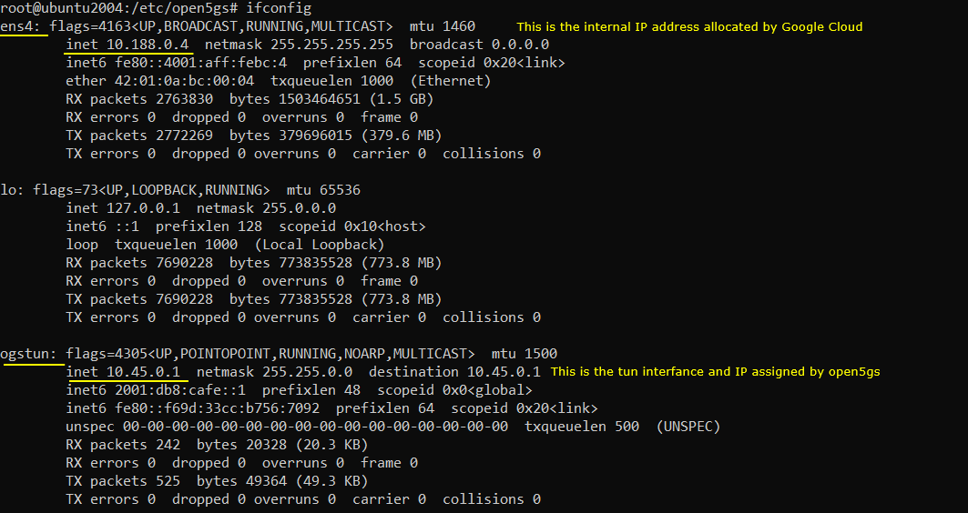
The NIC and IP configuration after installing Open5GS on the virtual machine is shown below.

In this example, the main network interface is ens4. This interface has the IP address 10.188.0.4, which is the internal IP address assigned by Google Cloud. This is the private IP address used inside the Google Cloud network. Open5GS components running on the VM can bind to this address when they need to use the VM network interface.

You can also see another interface called ogstun. This is the tunnel interface created by Open5GS. In this setup, ogstun has the IP address 10.45.0.1. This interface is used for the UE data network side. When the UE gets a PDU session, the UE traffic is routed through this tunnel interface inside Open5GS.

So, in this configuration, 10.188.0.4 is the Google Cloud internal IP address of the VM, and 10.45.0.1 is the Open5GS tunnel interface address. These two addresses have different roles. The ens4 address is used for communication between the VM and external network entities, while the ogstun address is used internally by Open5GS for UE user-plane traffic.

Cloud Open5GS Configuration 02

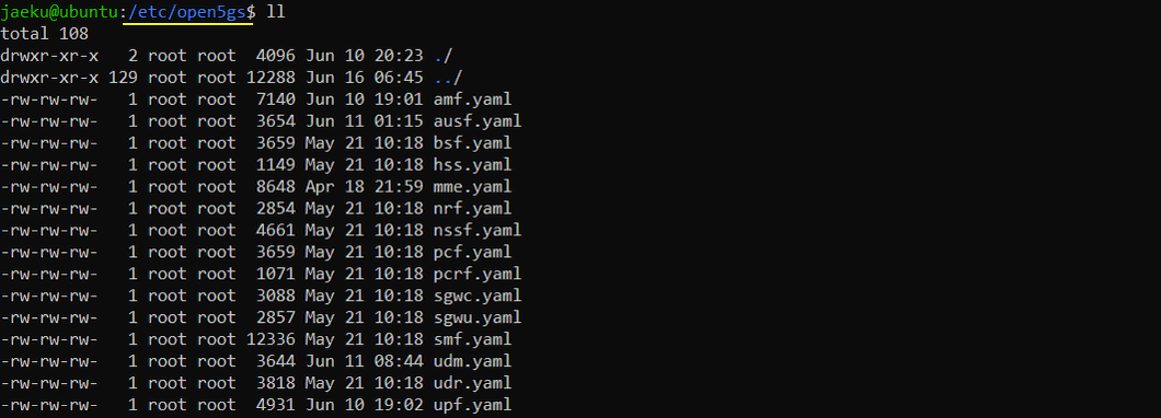
The Open5GS configuration files are located under /etc/open5gs.

In this directory, each Open5GS network function has its own YAML configuration file. For example, amf.yaml is used for AMF configuration, smf.yaml is used for SMF configuration, and upf.yaml is used for UPF configuration. Other files such as ausf.yaml, nrf.yaml, nssf.yaml, pcf.yaml, udm.yaml, udr.yaml, and bsf.yaml are used for the other Open5GS core network functions.

For this tutorial, the most important files are amf.yaml, smf.yaml, and upf.yaml. These files need to be checked or modified carefully because they define how the AMF, SMF, and UPF communicate with the Amarisoft gNB and how the user-plane traffic is handled. In the following steps, we will mainly focus on these configuration files.

MME Open5GS Configuration Open5GS 03

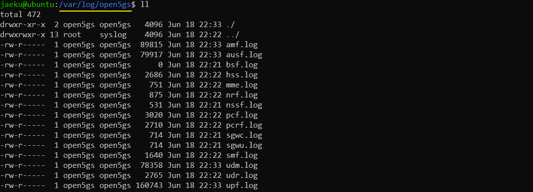
The Open5GS log files are stored under /var/log/open5gs.

In this directory, each Open5GS network function has its own log file. For example, amf.log is used for AMF logs, smf.log is used for SMF logs, and upf.log is used for UPF logs. Other log files such as ausf.log, nrf.log, nssf.log, pcf.log, udm.log, udr.log, and bsf.log are used for the other Open5GS core network functions.

These log files are very useful when you troubleshoot the connection between the Amarisoft gNB and Open5GS. For example, if the gNB cannot connect to the Core, you should first check amf.log because NGAP signaling from the gNB terminates at the AMF. If the UE can register but the data path does not work, you should check smf.log and upf.log because they are related to PDU session establishment and user-plane traffic.

In this tutorial, we will mainly use these logs to confirm whether the gNB connects to the AMF correctly, whether the UE registration is successful, and whether the user-plane path is created properly.

MME Open5GS Configuration Open5GS 04

Open5GS - User DataBase

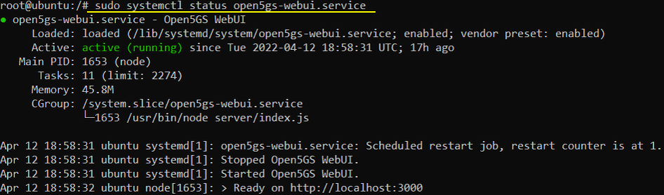
Before adding the UE subscriber information, first make sure that the Open5GS WebUI service is running properly.

You can check the WebUI service status with the following command.

In this example, the service status is shown as active (running), which means the Open5GS WebUI is running successfully. The log also shows that the WebUI is ready on [http://localhost:3000](http://localhost:3000).

If the Open5GS WebUI is installed but not running, you can restart it with the following command.

The Open5GS WebUI is used to add and manage UE subscriber information, such as IMSI, security keys, OPC, APN/DNN, and slice information. This information should match the UE or UE simulator configuration. Otherwise, the UE may fail during registration or PDU session establishment.

MME Open5GS Configuration Open5GS UserDB 01

Then with the web browser, you can add a subscriber information to open5gs User Database as below. (If you are not familiar with WebUI setup, refer to this note from sharetechnote).
NOTE : Since you cannot launch GUI directly on Cloud, you would need to connect GUI based Remote Desktop to the Virtual Machine on GUI and run the WebUI on the remote desktop or you would need to get access to the open5gs WebUI from a remote PC.  All my attempt to connect GUI based remote desktop to the Virtual Machine on Cloud failed, so I need to get access to open5gs WebUI from remote PC which requires some configuration change as shown in this note from sharetechnote.

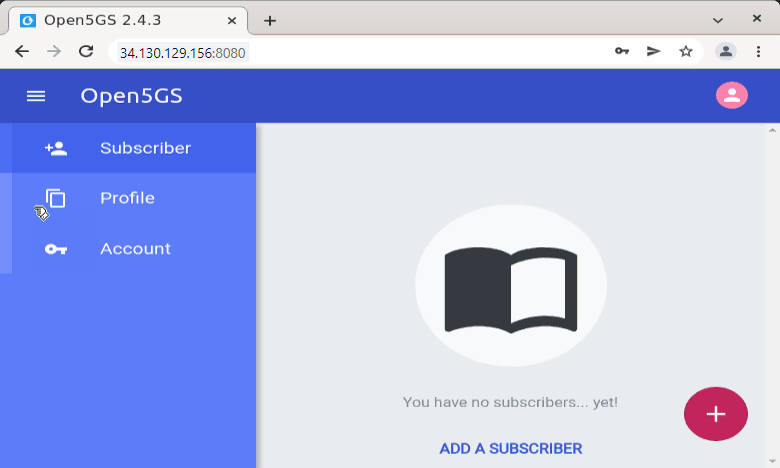
After confirming that the Open5GS WebUI service is running, you can open the WebUI from a browser using the external IP address of the cloud VM.

In this example, the Open5GS WebUI is accessed with the following address.

The IP address 34.130.129.156 is the external public IP address of the Google Cloud VM, and port 8080 is the port allowed by the cloud firewall rule. Even though the WebUI service itself is shown as ready on localhost:3000 inside the VM, it can be accessed from outside through the configured external port.

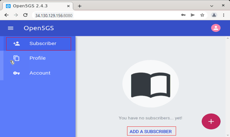
When you open the WebUI for the first time, there may be no subscriber information registered yet. In that case, the Subscriber page shows that there are no subscribers. To add a UE, click ADD A SUBSCRIBER. This is where you configure the subscriber information that should match the UE or UE simulator configuration, such as IMSI, key, OPC, APN/DNN, and slice information.

Cloud Open5GS Configuration Open5GS UserDB 02

From the Open5GS WebUI, select Subscriber from the left menu and click ADD A SUBSCRIBER.

At this point, the subscriber database is still empty, so the WebUI shows You have no subscribers... yet!. To register a UE, you need to add a new subscriber profile from this page. The subscriber information entered here must match the UE configuration used in Amarisoft UEsim or the real UE SIM profile. Especially, values such as IMSI, authentication key, OPC, DNN/APN, and slice information should be configured consistently between the UE side and Open5GS.

In this tutorial, we will add a subscriber entry first and then use that subscriber information for the UE registration test with the Amarisoft gNB connected to the Open5GS Core on the cloud.

Cloud Open5GS Configuration Open5GS UserDB 03

In the subscriber configuration page, enter the UE authentication information. This information should match the SIM profile used by the UE or UEsim.

In this example, the IMSI is configured as 001010000000001. The Subscriber Key is configured as 00112233445566778899AABBCCDDEEFF. The USIM Type is set to OPc, and the Operator Key is configured as 000102030405060708090A0B0C0D0E0F. The Authentication Management Field is set to 9001.

The UE-AMBR Downlink and UE-AMBR Uplink are both configured as 1 Gbps. These values define the aggregate maximum bit rate allowed for the subscriber. For basic registration and data test, the most important part is that IMSI, key, OPc, and AMF are configured correctly and consistently with the UE side.

After entering these values, continue with the remaining subscriber settings such as slice and session information, and then save the subscriber profile.

Cloud Open5GS Configuration Open5GS UserDB 04

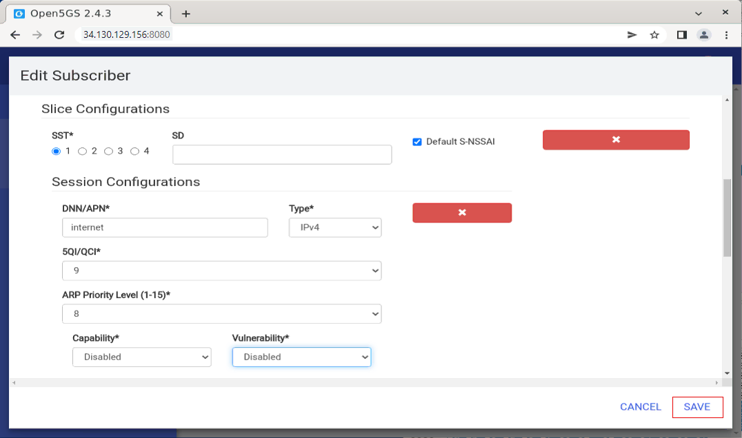
In the lower part of the subscriber configuration page, configure the slice and session information for the UE.

In this example, SST is set to 1, and Default S-NSSAI is enabled. SD is left empty. This means the subscriber is configured with the default slice using SST 1.

In the Session Configurations section, DNN/APN is configured as internet, and the session type is set to IPv4. This DNN value should match the DNN configured on the UE side or in the Amarisoft UE simulator. If the DNN does not match, UE registration may succeed, but PDU session establishment can fail.

The 5QI/QCI value is set to 9, which is commonly used for default best-effort data service. ARP Priority Level is set to 8. Capability and Vulnerability are both set to Disabled in this example.

After confirming these slice and session parameters, click SAVE to store the subscriber profile in the Open5GS database. Once this is saved, Open5GS will be ready to authenticate this UE and allow it to establish a PDU session using the configured DNN and slice.

Cloud Open5GS Configuration Open5GS UserDB 05

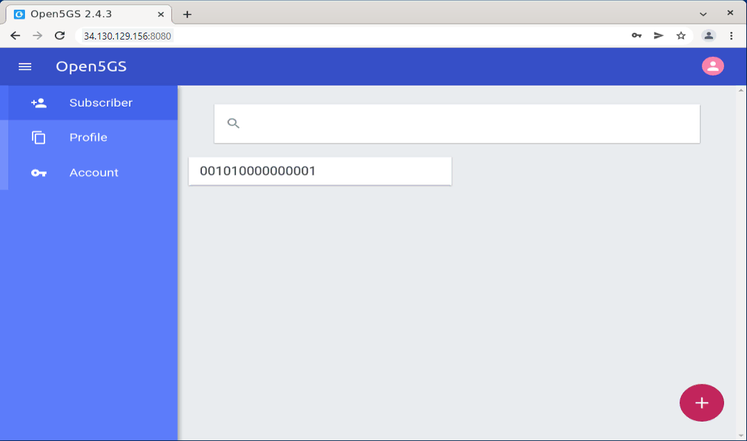
After saving the subscriber profile, the newly added IMSI appears in the Subscriber list.

In this example, the subscriber IMSI 001010000000001 is now registered in the Open5GS database. This confirms that the UE subscription information has been successfully added. From this point, Open5GS can use this subscriber profile during UE registration and authentication.

If you want to check or modify the subscriber configuration later, click the IMSI entry from this list. You can then review or update the authentication information, slice configuration, and DNN/APN settings.

At this stage, the Open5GS user database configuration is ready. The next step is to make sure that the Amarisoft UE or UEsim is configured with matching IMSI, key, OPc, DNN, and slice information so that the UE can successfully register to the Open5GS Core.

Cloud Open5GS Configuration Open5GS UserDB 06

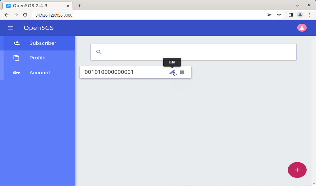
If you want to change the information for an existing UE, you can edit the subscriber profile from the Subscriber list.

In this example, the subscriber IMSI 001010000000001 is already registered. When you move the mouse over this subscriber entry, the Edit icon appears. Click the Edit icon to open the subscriber configuration page again.

From the Edit page, you can modify the UE authentication information, such as Subscriber Key, OPc, and AMF, as well as slice and session information such as SST, DNN/APN, session type, and 5QI/QCI. After modifying the required fields, click SAVE to apply the change.

This is useful when the UE registration fails due to a mismatch between the UE-side configuration and the Open5GS subscriber database. In that case, check the UE configuration first, then update the corresponding subscriber information from this Edit menu.

Cloud Open5GS Configuration Open5GS UserDB 07

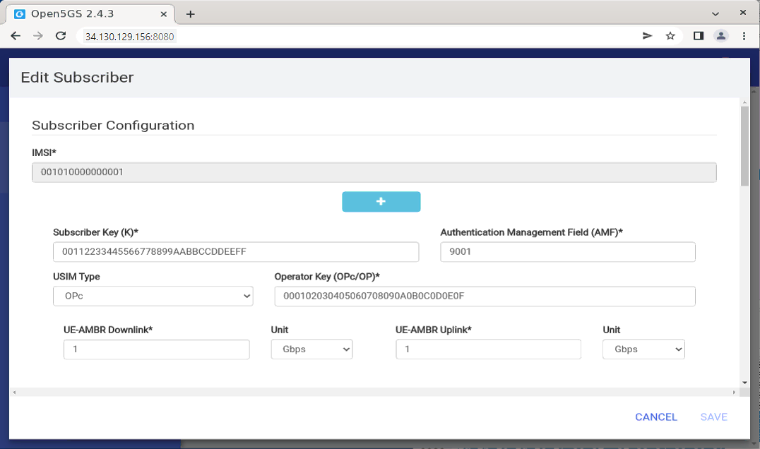
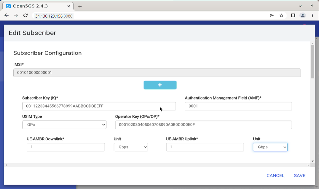
In the Edit Subscriber page, you can review or modify the main subscriber configuration.

In this example, the IMSI is 001010000000001. This value is fixed for the subscriber entry and should match the IMSI configured in the UE or Amarisoft UEsim.

The Subscriber Key is configured as 00112233445566778899AABBCCDDEEFF, and the Authentication Management Field is set to 9001. The USIM Type is set to OPc, and the Operator Key field contains the OPc value 000102030405060708090A0B0C0D0E0F. These authentication parameters must be exactly the same as the UE-side SIM configuration. If any of these values are different, the UE authentication will fail during registration.

The UE-AMBR Downlink and UE-AMBR Uplink are both set to 1 Gbps. These values define the maximum aggregate bit rate allowed for this subscriber. For this tutorial, the default value is enough for basic registration and data testing.

After checking or modifying these values, scroll down to confirm the slice and session configuration as well. When all values are correct, click SAVE to apply the updated subscriber configuration.

Cloud Open5GS Configuration Open5GS UserDB 08

Callbox

The detailed callbox configuration would very for each test case, so the detailed configuration will be described under each test case, but following network configuration would stay same for all the test case in my setup.

(NOTE : The IP address of the NIC of the callbox would be different in your test setup. You should change the IP addresses in each of the configurations for each test according to the IP of your own test setup)

On the Callbox side, check the IP address assigned to the network interface that is connected to the home or office network.

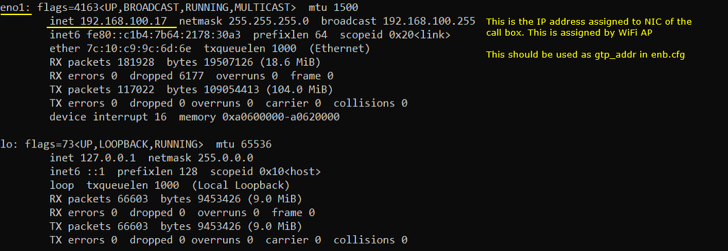
In this example, the main network interface is eno1, and its IP address is 192.168.100.17. This IP address is assigned by the Wi-Fi access point or router in the local network. Since the Amarisoft Callbox uses this interface to send and receive GTP-U traffic, this IP address should be used as gtp_addr in enb.cfg.

The important point is that gtp_addr should be the local IP address of the Callbox network interface. In this setup, that value is 192.168.100.17. However, because the Callbox is behind a home router, this local IP address is not directly reachable from the Open5GS cloud VM. Therefore, the public IP address of the home router should also be configured separately as gtp_ext_addr in enb.cfg.

So, in this setup, 192.168.100.17 is used as the local GTP-U address of the Callbox, and the home router public IP address is used as the external GTP-U address advertised to the cloud Core.

Cloud mme Configuration Callbox 01

UEsim

The same UEsim configuration will be used for all test cases in this tutorial.

In this example, the current ue.cfg file is linked to ue-nr-sa-open5gs.cfg. This means that when UEsim is started with the default ue.cfg, it will actually use the UE configuration prepared for NR SA with Open5GS.

You can check this with the following command.

The result shows that ue.cfg is a symbolic link pointing to ue-nr-sa-open5gs.cfg. Therefore, if you want to modify the UE configuration used in this tutorial, you should edit ue-nr-sa-open5gs.cfg, or make sure that ue.cfg points to the correct Open5GS-specific UE configuration file.

This configuration should match the subscriber profile created in the Open5GS WebUI. Especially, IMSI, key, OPc, DNN/APN, and slice information should be consistent between UEsim and the Open5GS subscriber database.

MME Open5GS Configuration UEsim 01

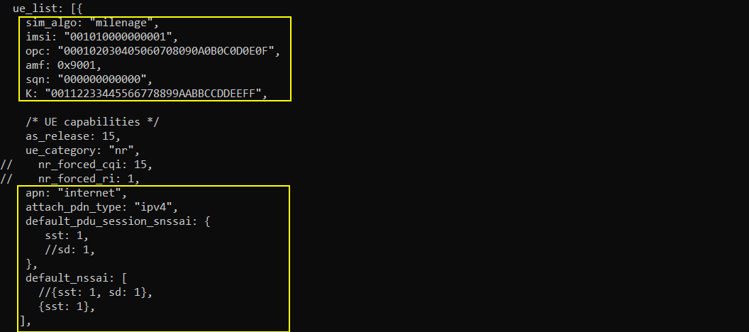
The following example shows the UE information configured in ue-nr-sa-open5gs.cfg. This file was copied from the original ue-nr.cfg and then modified for the Open5GS test setup.

In the USIM configuration, the IMSI is set to 001010000000001, and the authentication key K is set to 00112233445566778899AABBCCDDEEFF. The OPc value is configured as 000102030405060708090A0B0C0D0E0F, and AMF is set to 0x9001. These values should match the subscriber information configured in the Open5GS WebUI. If any of these values are different between UEsim and Open5GS, UE authentication will fail during the registration procedure.

The APN is configured as internet, and attach_pdn_type is set to ipv4. This should also match the DNN/APN and session type configured in the Open5GS subscriber profile. In this tutorial, the Open5GS subscriber was configured with DNN/APN internet and IPv4 session type, so the UEsim configuration uses the same values.

The default PDU session S-NSSAI is configured with SST 1. The default NSSAI list also includes SST 1. This matches the default slice configuration used in Open5GS. In this example, SD is not used, so only SST 1 is configured. With these settings, the UE can request the default slice and establish a PDU session using the internet DNN.

MME Open5GS Configuration UEsim 02

Test 1 : Amari gNB + Open5GS

In this test, I will show you a case where Amarisoft callbox is used as 5G/NR RAN only and Open5GS as a whole core network (i.e, AMF + AUSF + UDM + SMF + UPF and everything else).

Configuration

Open5gs

In this test, only three Open5GS configuration files are modified from the default configuration. All other Open5GS configuration files remain unchanged.

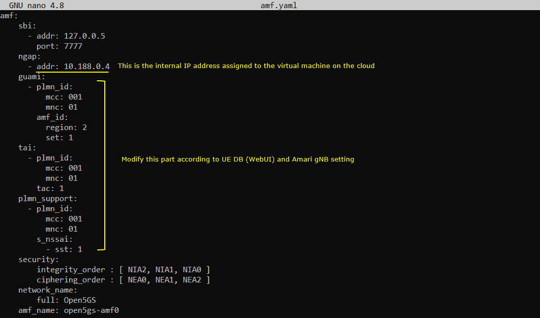
The first file to modify is amf.yaml. In this file, the NGAP address should be configured with the internal IP address of the Google Cloud VM. In this example, the NGAP address is set to 10.188.0.4. This is the internal IP address assigned to the VM network interface by Google Cloud.

You also need to check the GUAMI, TAI, and PLMN support configuration. In this example, MCC is set to 001 and MNC is set to 01. The TAC is set to 1, and the supported S-NSSAI is configured with SST 1. These values should match the configuration used in the Amarisoft gNB and the subscriber information configured in the Open5GS WebUI.

The important point is that the AMF should listen on the proper cloud VM internal interface for NGAP, while the PLMN, TAC, and slice information should be consistent across Open5GS, Amarisoft gNB, and UE subscriber configuration. If these values do not match, the gNB may connect to the AMF, but UE registration or slice selection may fail later.

Cloud Open5GS Test 1 Configuration Open5gs 01

The next file to modify is upf.yaml.

In this file, the GTP-U address is configured as 10.188.0.4. This is the internal IP address assigned to the Google Cloud VM. The UPF binds to this local interface inside the cloud VM.

Since the Amarisoft gNB is located outside the Google Cloud network, the gNB cannot directly reach this internal IP address. Because of this, the advertise field is configured with the external public IP address of the cloud VM, 34.130.129.156. This is the address that will be advertised to the gNB as the reachable UPF address.

In this setup, addr and advertise have different roles. The addr value is the local IP address used by the UPF process on the VM, while advertise is the public IP address announced to the external gNB. If advertise is not configured correctly, the UE may complete registration, but the user-plane path may fail because the gNB does not know the correct public address to reach the UPF.

The subnet is configured as 10.45.0.1/16. This corresponds to the Open5GS UE data network side, which is associated with the ogstun interface. This subnet is used for UE PDU session traffic after the UE gets an IP address from Open5GS.

Cloud Open5GS Test 1 Configuration Open5gs 06

The next file shown here is ausf.yaml.

For this test, no special change is required in ausf.yaml. The AUSF SBI address remains as the default local address, 127.0.0.11, and the SBI port remains 7777.

Since AUSF communicates with the other Open5GS core functions internally through the SBI interface, it does not need to be exposed directly to the Amarisoft gNB or to the external network. Therefore, this file can remain the same as the default Open5GS configuration.

In this test, the main external-facing configuration is done mainly in amf.yaml and upf.yaml. AUSF can stay with the default localhost-based SBI configuration.

Cloud Open5GS Test 1 Configuration Open5gs 03

The next file shown here is udm.yaml.

For this test, no special change is required in udm.yaml. The UDM SBI address remains as the default local address, 127.0.0.12, and the SBI port remains 7777.

UDM is used internally by Open5GS for subscriber-related functions. It communicates with other Open5GS core components through the SBI interface, but it does not communicate directly with the Amarisoft gNB. Because of this, it does not need to use the cloud VM external IP address.

So, in this setup, udm.yaml can remain the same as the default Open5GS configuration. The important configuration changes for connecting the external Amarisoft gNB are mainly in amf.yaml and upf.yaml.

Cloud Open5GS Test 1 Configuration Open5gs 04

The next file shown here is smf.yaml.

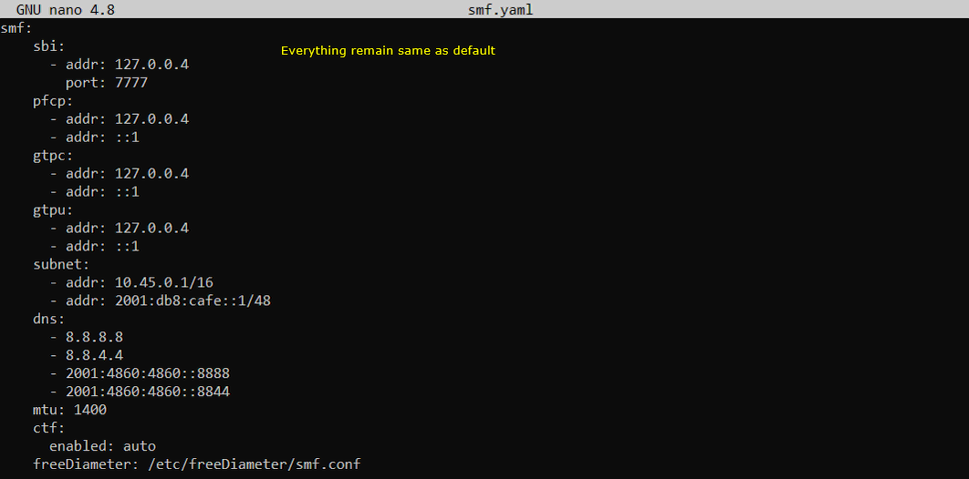
For this test, no special change is required in smf.yaml. The SMF SBI address remains as the default local address, 127.0.0.4, and the SBI port remains 7777.

The PFCP address is also configured as 127.0.0.4. This is used for communication between SMF and UPF. Since SMF and UPF are running on the same Open5GS cloud VM in this test, this localhost-based configuration can remain unchanged.

The subnet is configured as 10.45.0.1/16, which matches the UE data network subnet associated with the ogstun interface. This is the subnet used when Open5GS assigns an IP address to the UE during PDU session establishment.

The DNS servers are configured as 8.8.8.8 and 8.8.4.4 for IPv4, and 2001:4860:4860::8888 and 2001:4860:4860::8844 for IPv6. These DNS settings are provided to the UE as part of the PDU session configuration.

In this setup, SMF does not need to be exposed directly to the Amarisoft gNB. Therefore, smf.yaml can remain the same as the default Open5GS configuration. The main files that need cloud-specific changes are still amf.yaml and upf.yaml.

Cloud Open5GS Test 1 Configuration Open5gs 05

Once you modify any Open5GS configuration file, you need to restart the corresponding Open5GS service so that the change can take effect.

For example, if you modified amf.yaml, restart open5gs-amfd. If you modified upf.yaml, restart open5gs-upfd. If you modified ausf.yaml or udm.yaml, restart open5gs-ausfd or open5gs-udmd accordingly.

In this example, the following services are restarted.

$ sudo systemctl restart open5gs-amfd

$ sudo systemctl restart open5gs-ausfd

$ sudo systemctl restart open5gs-upfd

$ sudo systemctl restart open5gs-udmd

You do not always need to restart every Open5GS component. In general, restart only the service related to the configuration file that you changed. However, if you are not sure which component is affected, restarting the related core components together can help avoid using an old configuration by mistake.

Callbox

In this test, gnb-sa-open5gs-cloud.cfg is used as gNB configuration and it is copied and modified from gnb-sa.cfg.

Cloud Open5GS Test 1 Configuration Callbox 01

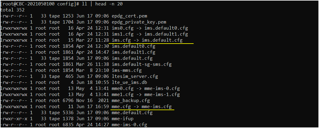
For mme, no special configurations are used. Everything is used as default configuration. ( NOTE : Actually it doesn't really matter which mme cfg file you specifies in this tutorial because Amari MME is not used at all in this tutorial.).
MME Open5GS Test 1 Configuration Callbox 02

The configuration in gnb-sa-open5gs-cloud.cfg are set as follows (NOTE : In this case, Network Address Translation happens between aaa.bbb.ccc.ddd and 192.168.100.17.  This tranlation is done by Linux, not by Amari MME)

In this setup, amf_addr is configured as 34.130.129.156. This is the external public IP address of the Google Cloud VM where Open5GS AMF is running. The Amarisoft gNB uses this address to establish the NGAP connection with the AMF.

The gtp_addr is configured as 192.168.100.17. This is the local IP address of the Callbox PC. This address is assigned to the Callbox network interface by the Wi-Fi access point or local router. The Callbox uses this address as its local GTP-U bind address.

The gtp_ext_addr is configured as aaa.bbb.ccc.ddd. This is the external public IP address of the home or office router that the Callbox is connected to. Since the Callbox is behind NAT, the cloud UPF cannot directly reach 192.168.100.17. Instead, the UPF sees the Callbox side through the router public IP address. Therefore, this public IP address should be advertised as the external GTP-U address.

In this case, Network Address Translation happens between aaa.bbb.ccc.ddd and 192.168.100.17. This NAT is handled by the local network or Linux/router configuration, not by Amarisoft MME. The important point is that gtp_addr should be the local Callbox IP address, while gtp_ext_addr should be the public IP address that the Open5GS cloud side can use to send GTP-U traffic back toward the Callbox.

Cloud Open5GS Test 1 Configuration Callbox 03

Perform the Test

First, restart the LTE service on the Callbox and check the basic gNB configuration as shown below. In this test, the detailed radio cell configuration is not very important. You can configure the NR cell according to your own test requirement, as long as the gNB can start properly and connect to the Open5GS AMF.

In this example, the cell phy command shows that the gNB is running with PLMN 00101 and gNB_ID 0x12345. The NR cell is configured on band n78 with 20 MHz bandwidth. The DL ARFCN and UL ARFCN are both set to 632628, and the SSB ARFCN is set to 632544. The subcarrier spacing is 30 kHz.

The cell command also confirms the basic cell information. The cell ID is 0x001, the TAC is 1, the PCI is 500, and the PLMN is 00101. These values should be consistent with the Open5GS AMF configuration, especially PLMN and TAC. If PLMN or TAC does not match between the gNB and Open5GS, the gNB may start normally, but UE registration can fail later.

At this point, the important check is that the Amarisoft gNB is running with the expected PLMN, TAC, and NR cell configuration before trying UE registration through the Open5GS Core on the cloud.

MME Open5GS Test 1 Run 01

Check the core network connection status from the Callbox.

You can use the ng command to check whether the gNB is connected to the Open5GS AMF. In this example, the NG connection state is shown as setup_done, which means the NGAP connection between the Amarisoft gNB and the Open5GS AMF has been successfully established.

The server address is shown as 34.130.129.156:38412. This is the external public IP address of the Google Cloud VM, and port 38412 is the standard SCTP port used for NGAP. The PLMN is shown as 00101, which matches the PLMN configured in both the Amarisoft gNB and Open5GS AMF.

At this point, the gNB-to-Core control-plane connection is working. This confirms that the AMF address, cloud firewall rule for SCTP, and PLMN-related configuration are properly set for the NGAP connection.

Cloud Open5GS Test 1 Run 02

Now restart the LTE service on UEsim and power on the UE.

In this example, the UE is powered on with the power_on command. After power on, the UE starts cell search and successfully finds the SIB from the gNB. The message SIB found means that the UE can detect the NR cell and read the basic system information broadcast by the Amarisoft gNB.

At this point, the radio-side access is working at least up to SIB decoding. The next step is to check whether the UE can continue with registration through the Amarisoft gNB and the Open5GS Core running on the cloud.

MME Open5GS Test 1 Run 03

If the connection is successfully completed, the UE should be registered and assigned with an IP address as shown below.

In this example, the ue command shows that the UE is in running state and the EMM state is registered. This means the UE has successfully completed the registration procedure through the Amarisoft gNB and the Open5GS Core on the cloud.

The UE is also assigned the IP address 10.45.0.2. This IP address comes from the Open5GS UE subnet configured in smf.yaml and upf.yaml, where the subnet is set to 10.45.0.1/16. This confirms that the PDU session has been established successfully and that Open5GS has assigned an IP address to the UE.

At this point, both the control plane and user plane setup are working. The NGAP connection between gNB and AMF is established, the UE is registered, and the UE has received an IP address from the Open5GS Core.

MME Open5GS Test 1 Run 04

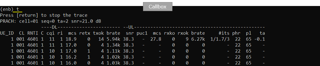
You can confirm the UE connection from the Callbox by using the t command and the ue command.

The t command shows the real-time radio link status of the connected UE. In this example, UE ID 1 is connected to cell 001 with RNTI 4601. The trace shows DL and UL scheduling information, such as CQI, RI, MCS, retransmission count, bitrate, SNR, PHR, and timing advance. This confirms that the UE is not only registered, but also actively connected at the radio level.

The ue command shows the UE context managed by the gNB. In this example, RAN_UE_ID 1 is mapped to CN_UE_ID 1, and the UE is connected to cell 0x001 with RNTI 0x4601. This confirms that the UE context is created between the Amarisoft gNB and the Open5GS Core.

At this point, the UE is successfully connected through the Amarisoft gNB to the Open5GS Core running on the cloud. The gNB has an active UE context, and the radio trace confirms that the UE is exchanging traffic with the cell.

MME Open5GS Test 1 Run 05

MME Open5GS Test 1 Run 06

Try ping from the cloud Open5GS VM to the UE IP address.

In this example, the UE was assigned the IP address 10.45.0.2, so the ping test is performed from the cloud VM with the following command.

The ping response shows that ICMP packets are successfully received from 10.45.0.2. This confirms that the user-plane path from the Open5GS cloud VM to the UE is working properly.

The measured round-trip time is around 23 ms to 41 ms in this example. This delay is expected because the Open5GS Core is running on Google Cloud while the Amarisoft Callbox and UEsim are located in the local home network. Therefore, the traffic has to pass through the internet and NAT path between the cloud Core and the local RAN.

At this point, the UE has successfully registered, received an IP address, and responded to ping from the Open5GS cloud VM. This confirms that both the control plane and user plane are working in the Amarisoft gNB + Open5GS cloud setup.

Cloud Open5GS Test 1 Run 07

Log Analysis

Sample Log

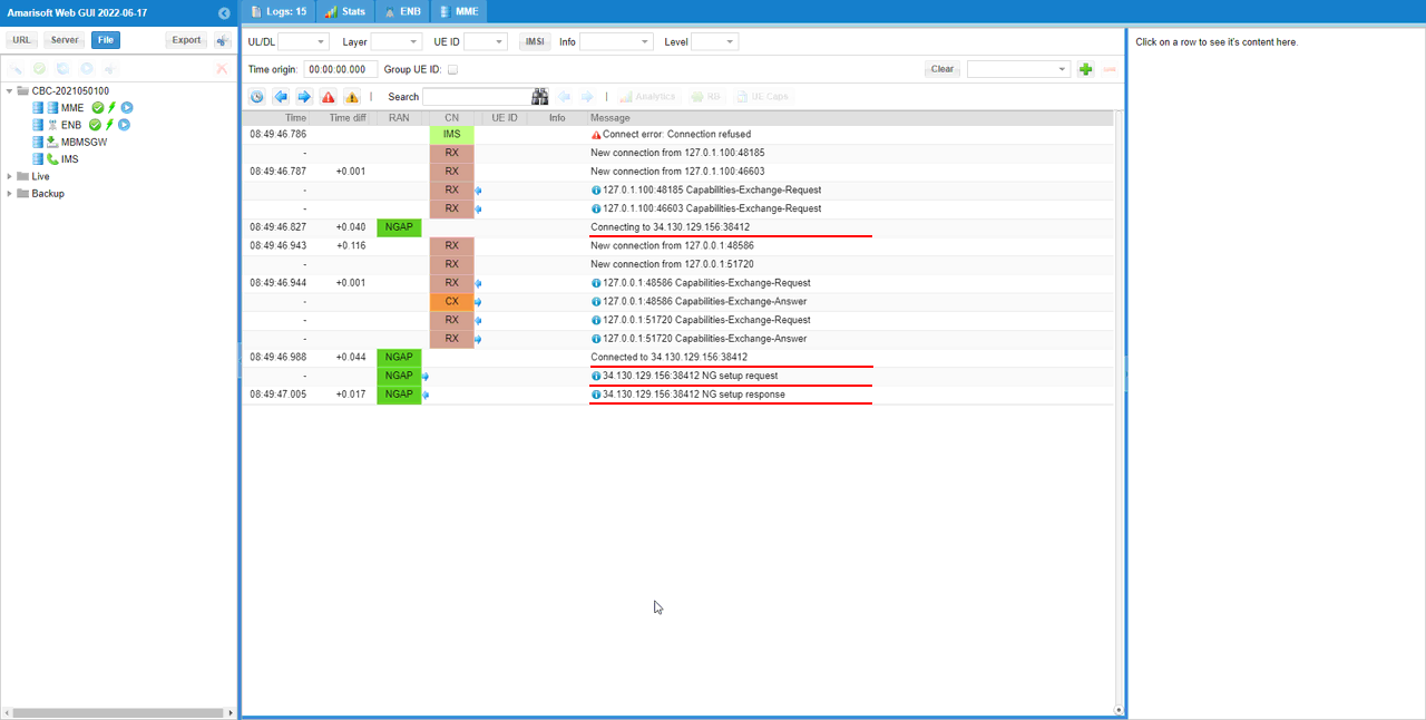
As soon as you start the LTE service on the Callbox, the gNB tries to establish an NGAP connection to the AMF. If the gNB is successfully connected to the Open5GS Core on the cloud, you should see the NGAP connection log as shown below.

In this example, the log shows that the gNB is connecting to 34.130.129.156:38412. This is the external public IP address of the Google Cloud VM, and 38412 is the SCTP port used for NGAP. After the connection attempt, the log shows Connected to 34.130.129.156:38412, which means the SCTP connection to the AMF has been established successfully.

After the connection is established, the gNB sends the NG setup request to the AMF. Then the AMF sends back the NG setup response. This confirms that the basic NGAP setup procedure between the Amarisoft gNB and Open5GS AMF has completed successfully.

At this point, the gNB-to-Core control-plane connection is ready. This also confirms that the AMF address in the gNB configuration is correct, the cloud firewall allows SCTP traffic, and Open5GS AMF is reachable from the Callbox through the internet.

Cloud open5gs Test 1 Log 01

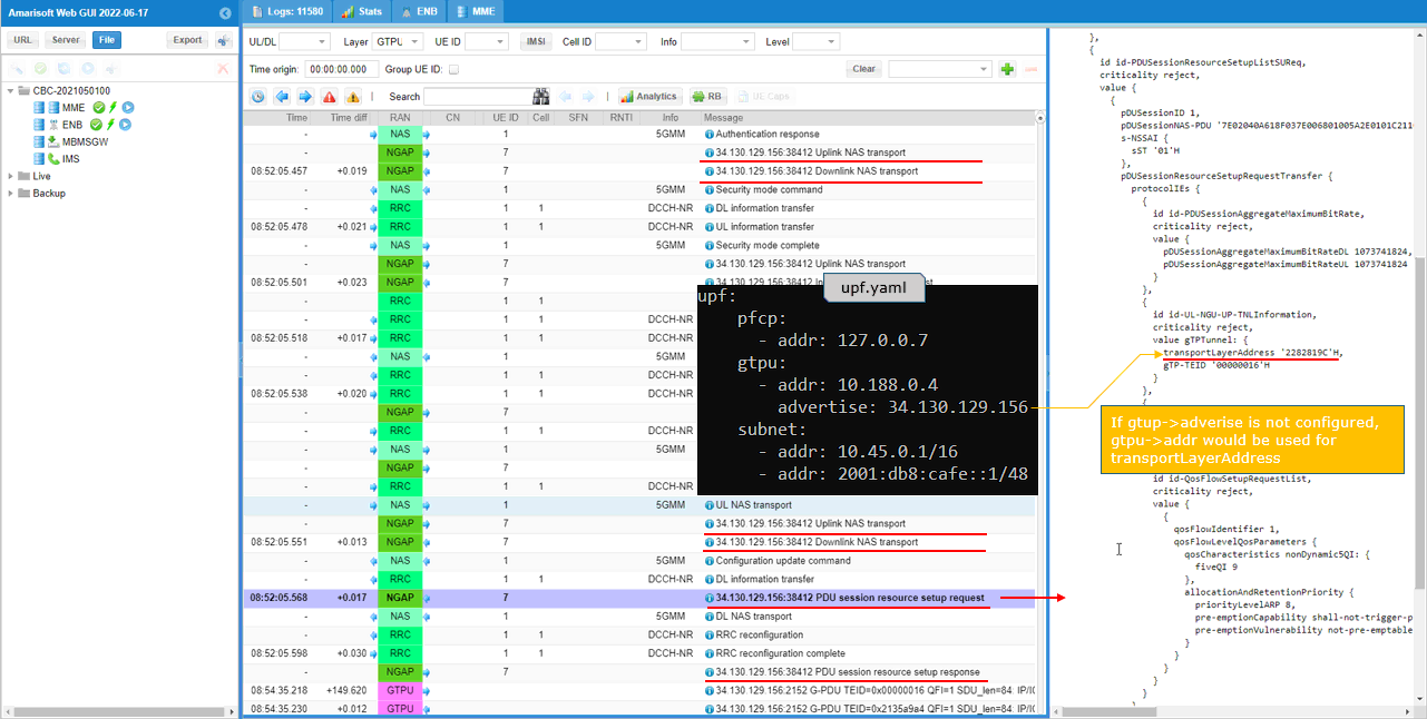
This log shows the UE registration and PDU session setup procedure after the NGAP connection is already established.

In the log, you can see the NAS and NGAP messages exchanged between the Amarisoft gNB and Open5GS AMF. The UE first completes the authentication and security procedure. After that, the UE sends NAS signaling for PDU session establishment, and the AMF sends NGAP messages such as Uplink NAS transport and Downlink NAS transport.

The important part in this example is the PDU session resource setup request. This message is sent from Open5GS AMF to the Amarisoft gNB. Inside this message, Open5GS provides the user-plane tunnel information that the gNB should use for GTP-U communication.

On the right side of the log, the transportLayerAddress is shown as 2282819C. This value corresponds to the advertised UPF IP address. In this setup, upf.yaml is configured with addr set to 10.188.0.4 and advertise set to 34.130.129.156. Therefore, Open5GS uses 34.130.129.156 as the address announced to the gNB for the UPF user-plane tunnel.

This is why the advertise field in upf.yaml is important in a cloud setup. If advertise is not configured, Open5GS may use the internal GTP-U address, 10.188.0.4, in the PDU session resource setup message. However, this internal IP address is only valid inside the Google Cloud network and cannot be reached directly by the Amarisoft gNB located at home or in the office. In that case, UE registration may still succeed, but the user-plane traffic can fail.

The log confirms that the PDU session setup is using the correct externally reachable UPF address. After this step, GTP-U traffic can be established between the Amarisoft gNB and the Open5GS UPF through the public network.

Cloud open5gs Test 1 Log 02

This log shows the PDU session resource setup response sent from the Amarisoft gNB back to Open5GS AMF.

In the previous step, Open5GS sent the PDU session resource setup request to the gNB and included the UPF tunnel information. After the gNB processed that request, it replied with the PDU session resource setup response. This response includes the gNB-side GTP-U tunnel information that Open5GS UPF should use when sending downlink user-plane packets toward the gNB.

The important field in this message is transportLayerAddress. In this example, the value is shown as 77F1E1D. This corresponds to the external IP address configured by gtp_ext_addr in enb.cfg. In this setup, gtp_addr is configured as 192.168.100.17, which is the local IP address of the Callbox, and gtp_ext_addr is configured as aaa.bbb.ccc.ddd, which is the public IP address of the router connected to the Callbox.

This is important because the Open5GS UPF is running on the cloud and cannot directly reach the private local IP address 192.168.100.17. If gtp_ext_addr is configured, Amarisoft uses this external public IP address in the PDU session resource setup response. Then Open5GS UPF can send GTP-U traffic toward the public IP address of the local router, and the traffic can be translated back to the Callbox through NAT.

If gtp_ext_addr is not configured, the gNB may use gtp_addr as the transportLayerAddress. In that case, the private IP address 192.168.100.17 would be sent to Open5GS. Since this private IP is not reachable from the cloud VM, UE registration may still complete, but downlink user-plane traffic can fail.

So, this log confirms that the gNB is advertising the correct externally reachable GTP-U address to Open5GS. Together with the advertise setting in upf.yaml, this completes both directions of the user-plane address configuration between the cloud UPF and the local Amarisoft gNB.

Cloud open5gs Test 1 Log 03

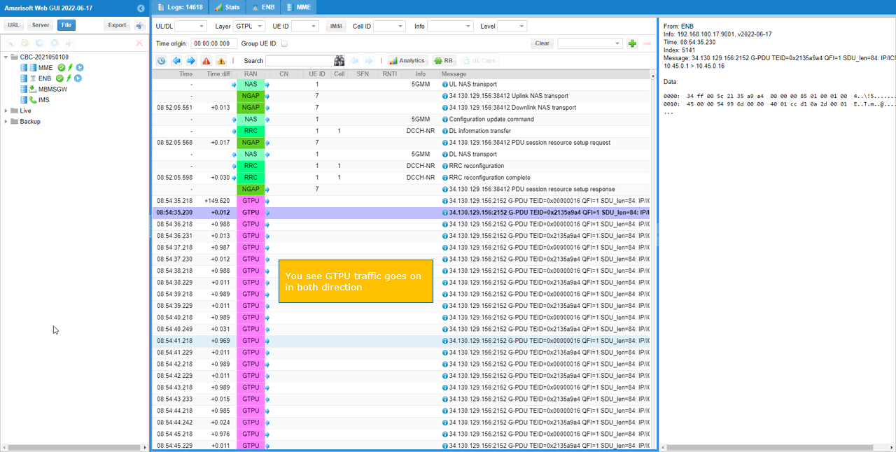
This log shows that GTP-U user-plane traffic is exchanged after the PDU session is established.

In the previous steps, the UE completed registration and the PDU session resource setup procedure. After that, you should start seeing GTP-U packets in the Amarisoft log, as shown in this example. The GTPU entries appear repeatedly, which means user-plane packets are flowing through the tunnel between the Amarisoft gNB and the Open5GS UPF.

You can also see GTP-U traffic in both directions. One direction corresponds to packets sent from the UE side toward the Open5GS UPF, and the other direction corresponds to packets sent from the Open5GS UPF toward the UE through the Amarisoft gNB.

This confirms that the user-plane tunnel is working properly. It also confirms that the UPF advertise address in upf.yaml and the gNB gtp_ext_addr in enb.cfg are configured correctly. If either of these external address settings is wrong, the UE may still register successfully, but GTP-U packets may not flow in both directions.

At this point, the full end-to-end path is verified. The gNB is connected to the cloud AMF, the UE is registered, the PDU session is established, and GTP-U user-plane traffic is exchanged between the local Amarisoft setup and Open5GS running on the cloud.

Cloud open5gs Test 1 Log 04