ARM-Callbox
This tutorial shows how to port Amarisoft callbox onto a ARM based embedded board. It is a good use case for low power and more portable solution like Small Cell or any other types of embedded system with cellular network functionality.
Table of Contents
Introduction
Amarisoft Callbox is a sophisticated, software-based LTE/5G test platform widely utilized for cellular network development, validation, and testing. By emulating base station and core network functionalities, it enables engineers to simulate real-world mobile network environments within a controlled lab setting. Traditionally, Amarisoft Callbox solutions have been deployed on x86-based server platforms due to their robust processing capabilities and compatibility with high-throughput networking hardware. However, the increasing demand for low-power, portable, and cost-effective solutions in the telecommunications industry has driven interest in porting the Amarisoft Callbox to ARM-based embedded boards. ARM architectures, known for their power efficiency, scalability, and integration in embedded and IoT devices, offer a compelling platform for deploying compact small cell solutions and extending cellular network functionality to a broader range of embedded systems. Successfully porting Amarisoft Callbox to ARM involves addressing architectural differences, optimizing software for ARM instruction sets, and ensuring compatibility with embedded Linux environments. This transition not only enhances the portability and energy efficiency of cellular test equipment but also enables innovative deployment scenarios—such as remote field testing, mobile network research, or edge computing for private LTE/5G networks—thereby expanding the role of Amarisoft Callbox within the evolving wireless ecosystem.
-
Context of the Technology
- Amarisoft Callbox enables comprehensive LTE and 5G cellular network simulation for development, testing, and validation.
- ARM-based embedded boards provide a lightweight, power-efficient computation platform, ideal for portable and small form-factor solutions.
- Porting to ARM allows integration into small cell deployments, IoT gateways, and edge computing nodes, broadening Amarisoft’s application scope.
-
Relevance and Importance of the Tutorial
- Demonstrates a practical approach to migrating sophisticated cellular network software to modern embedded architectures.
- Highlights the process of adapting high-performance telecom software for low-power, embedded environments.
- Addresses industry needs for flexible, cost-effective, and portable cellular network solutions for research, prototyping, and deployment.
-
Learning Outcomes
- Understand the requirements and challenges of porting Amarisoft Callbox to ARM-based embedded boards.
- Gain hands-on experience in configuring embedded Linux environments for telecom applications.
- Learn about ARM architecture specifics relevant to telecom workloads and software optimization.
- Acquire knowledge of practical deployment strategies for portable cellular network solutions.
-
Prerequisite Knowledge and Skills
- Solid understanding of cellular network concepts (e.g., LTE, 5G, base station architecture).
- Familiarity with embedded Linux environments, including kernel, drivers, and package management.
- Experience with cross-compilation and software porting between architectures (x86 to ARM).
- Basic knowledge of ARM hardware platforms and their peripheral interfaces.
- General programming/scripting skills for system integration and troubleshooting.
Summary of the Tutorial
This tutorial outlines the procedures for setting up and evaluating a 5G NR standalone (SA) test using a SolidRun Honeycomb embedded board and Amarisoft callbox software, with either SDR 100 or SDR 50 cards. The primary objective is to assess system performance, particularly with a 100 MHz bandwidth using 2x2 MIMO configuration.
-
Test Setup:
- Utilize the SolidRun Honeycomb board and the SIM card provided with the system.
- Connect either SDR 100 or SDR 50 to the single available PCI slot on the board.
- SDR 100 supports up to 4x4 MIMO (single cell) or two 2x2 MIMO cells; SDR 50 supports up to 2x2 MIMO (single cell).
- Install necessary callbox software and ensure proper board configuration.
-
Configuration Procedure:
- Edit and use the gnb-sa-100Mhz-2x2.cfg file, derived from gnb-sa.cfg.
- Configure key parameters:
- Set Duplex method (NR_TDD).
- Set channel bandwidth to 100 MHz (maximum single cell bandwidth).
- Specify MIMO scheme (N_ANTENNA_DL).
- Configure subcarrier spacing, SSB positions, cell lists, and other NR parameters as required.
- Keep RF driver settings as default unless specific changes are required for SDR100 or SDR50.
- For SDR100, both sdr0 and sdr1 can be configured on a single card (supports 4x4 MIMO); SDR50 supports only sdr0, limited to 2x2 MIMO.
- Use basic TDD band as default for initial testing.
-
Test Execution:
- Start LTE service and verify basic cell configuration.
- Use 'cell' and 'cell phy' commands to confirm proper cell setup.
- Power on the UE and allow it to attach to the configured cell.
- Send high-level IP data (e.g., flood UDP in downlink) to evaluate end-to-end performance.
-
Log Analysis:
- Review overall log text to confirm successful UE attach.
- Examine physical layer throughput plots and SNR/EPRE values to assess radio link quality.
- Adjust parameters such as rx_gain, tx_gain, antenna direction, and distance for optimal SNR/EPRE.
- Analyze RB map to observe downlink and uplink scheduling; expect fully loaded PDSCH slots in downlink-heavy tests, with minimal uplink utilization.
-
Limitations and Considerations:
- Only one SDR card can be used due to a single PCI slot on the Honeycomb board.
- SDR50: Limited to 2x2 MIMO and single cell; SDR100: Up to 4x4 MIMO (single cell) or two 2x2 MIMO cells, but 4x4 MIMO with 100 MHz bandwidth may cause underflow issues.
- Full downlink throughput for 100 MHz NR SA 2x2 MIMO was achieved; performance can be affected by CPU and physical resource limitations of the embedded board.
- Logging may be incomplete if WebGUI is used during high-throughput tests; for full stack logging, avoid running the WebGUI.
Test Setup
Test setup for this tutorial is as shown below.
- SIM Card used in this tutorial is the one delivered with the system as it is.
- If you want to change the configuration, The tutorial Configuration Guide would help
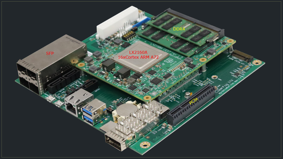
The embedded board used in this tutorial is SolidRun Honeycomb board as shown below. (
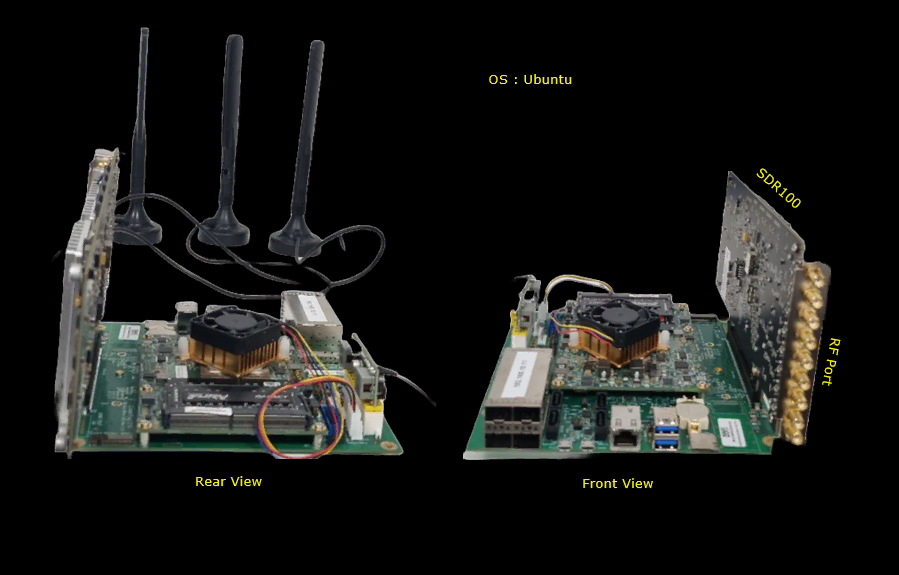
Following is the entire setup for this tutorial. In this tutorial, SDR 100 is used but it can work with SDR 50 as well.
Key Configuration Parameters
Followings are important configuration parameters for this tutorial. You may click on the items for the descriptions from Amarisoft documents.
Configuration
Once the pasic preparation for the installation and callbox software is installed properly, configuration for the test is exactly same as with regular callbox. You can do most of test that can be done by regular Amarisoft callbox (
For a simple test, I used the gnb-sa-100Mhz-2x2.cfg which is modified from gnb-sa.cfg

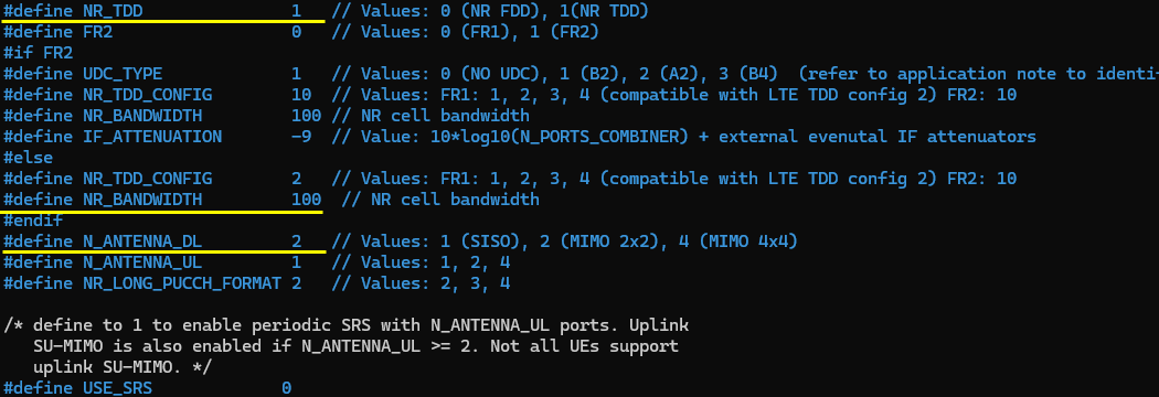
Configure gnb-sa-100Mhz-2x2.cfg as follows.
Specify Duplex method (NR_TDD), Channel Bandwidth (NR_BANDWIDTH) and MIMO Scheme(N_ANTENNA_DL). One thing that was configured specially for this test is the bandwidth. I set it to 100Mhz which is the maximum bandwidth for the single cell and it was to see the performance of the board is good enough for such a wide band.
RF driver setting is same as default (regular) setting. (

For this test, a basic TDD band is used as default setting.

Perform the test
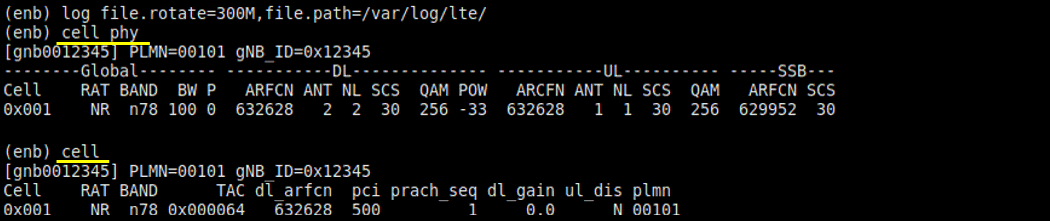
Start LTE service and check basic cell configuration.
Now try out 'cell' and 'cell phy' to check if the cell is configured as intended.
Power on UE and let UE attach to the cell.

You can try to flood high level IP data to get more clear idea on end-to-end performance.

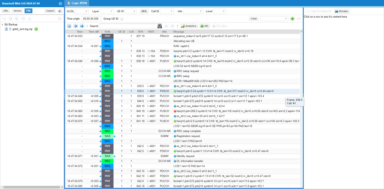
Log Analysis
First check on overall log text to see if the initial attach properly went through.
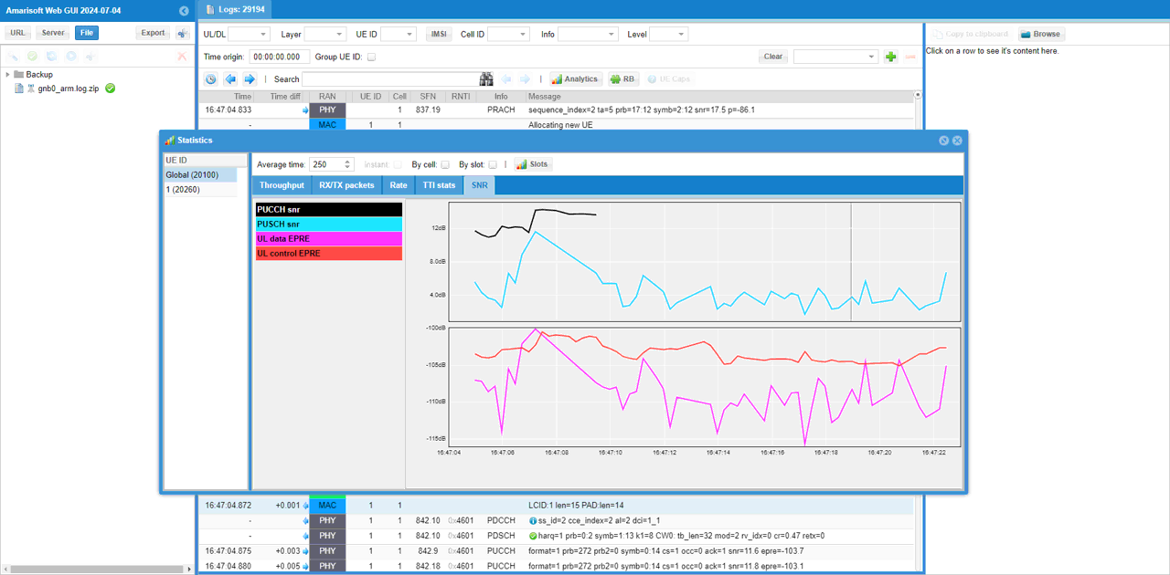
Then check out the throughput plot. This is physical layer throughput.

It would be good idea to check on SNR and EPRE to check radio link quality. You may adjust parameters (e.g, rx_gain, tx_gain, the direction of antenna and distance between UE and gNB antenna etc) to get the SNR/EPRE profile as good as possible.
You can check out the physica layer scheduling state with RB map as shown below. In this test, we flooded UDP in downlink and didn't inject any traffic in uplink. So you see most of the PDSCH slot are fully loaded and uplink slot is mostly empty.

Limitations
We are at relatively early stages of evaluating our software at ARM and Embedded board. We have faced some limitations with this kind of system which in most case understandable considering that the setup has an embedded system which has limited physical resources and lower performing CPUs comparing to high end PC. In this section, I will collect a list of limitations and restrictions that we faced during the evaluation.
Number of SDR Cards
Obviously this comes from the number of PCI slots available on the system. There is only one PCI slots on this board which means you can put only one SDR card on the system. This would cause various different limitations depending on whether you use SDR50 or SDR100.
- SDR50 : SDR50 can support only upto 2x2 MIMO and support only one cell with one sdr card. So if you use sdr50 with the board used in this tutorial, you will have these limination tied to SDR50.
- SDR100 : SDR100 can support upto 4x4 MIMO (4x4 MIMO single cell) and support up to 2 cells (each cell upto 2x2 MIMO) with one sdr card. So if you use sdr50 with the board used in this tutorial, "theoretically" you should be able to run 4x4MIMO single cell, but as far as I tried 4x4 MIMO causes underflow issues with bhe bandwidth goes very wide (like 100Mhz).
Performance
- Throughput : As of now, we achieved the full downlink throughput for NR SA 100Mhs Bandwidth with 2x2 downlink MIMO.
- Logging : Without WebGUI running turing the test, you would achieve full stack logging with full throughput, but a considerable amount of low layer logging would be skipped(i.e, not collected) if you are collecting the log with WebGUI