7.2 RU Integration Guide
This tutorial shows how to connect a 7.2 RU to Amarisoft Callbox over ORAN 7.2 interface. Both LLS-C1 and LLS-C3 architectures as per ORAN fronthaul specification for synchronisation and clock distribution between DU and RU will be explained with the relevant PTP configuration files.
Table of Contents
Hardware Requirements
- An AMARI Callbox Advanced/Ultimate/Extreme with 7.2 interface.
- A 10Gb Ethernet NIC with support of hardware PTP timestamping. In this tutorial, we use a 10G Intel E810-XXVDA2 card, given its tested capability to provide a reliable clock as PTP Grandmaster. The card is inserted in the PCIe slot of the Callbox.
- A 7.2 RU (Radio Unit). In this tutorial we use a Pegatron 1450 RU which has been successfully tested with Amarisoft gNB.
- Optical fiber cables for Callbox, RU and switch interconnections. In this tutorial, we use SFP+ DAC cables. In C3 topology, two 10Gbps DAC SFP+ cables are required to connect DU and RU to the switch. In C1 topology, one cable is enough between DU and RU.
- Fronthaul O-RAN switch and PTP Grand master: The switch is only needed in C3 topology to provide PTP clock and timing synchronization to both DU and RU. We use Fibrolan µFalcon-RX/206/G xHaul Switch & PTP Grandmaster.
Test Setup
LLS-C1 Test Setup
In this architecture, the RU is directly connected to the Callbox NIC card E810 via a SFP+ DAC cable. The Callbox plays the role of the PTP Grand master, providing the clock and synchronization information to the RU. This is depicted in the following diagram.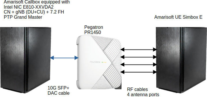
Configuration
This section provides the full configuration parameters to set up a fully functional 7.2 testbed.Linux Configuration
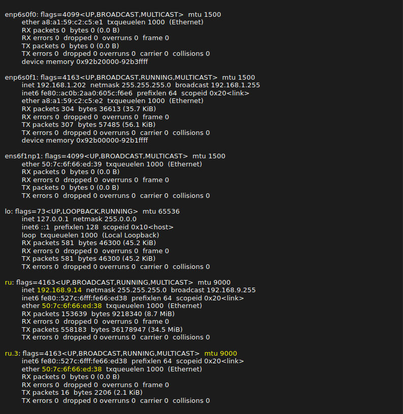
Before starting, you need to identify the network interfaces provided by the E810 card by typing ifconfig command in a Linux terminal. In my case, as it can be seen, the relevant interfaces are ens6f1np0 and ens6f1np1.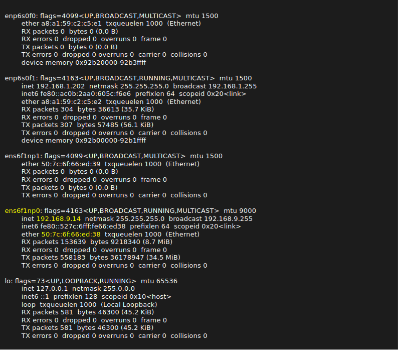
For Fedora < 42, you can simply copy the ifcfg-ru file under /etc/sysconfig/network-scripts directory.
Fedora 42 has switched to Network manager and stopped supporting ifcfg legacy files. The Network manager keyfile to fix the interface address should look like the file ifcfg-ru.nmconnection and should be copied under /etc/NetworkManager/system-connections/ directory. Changing the device name to ru requires creation of the file 70-custom.link under /etc/systemd/network directory. The HWADDR inside the ifcfg file, keyfile and link files should be set to the hardware MAC address of the Ethernet interface as shown in the output of the ifconfig command.
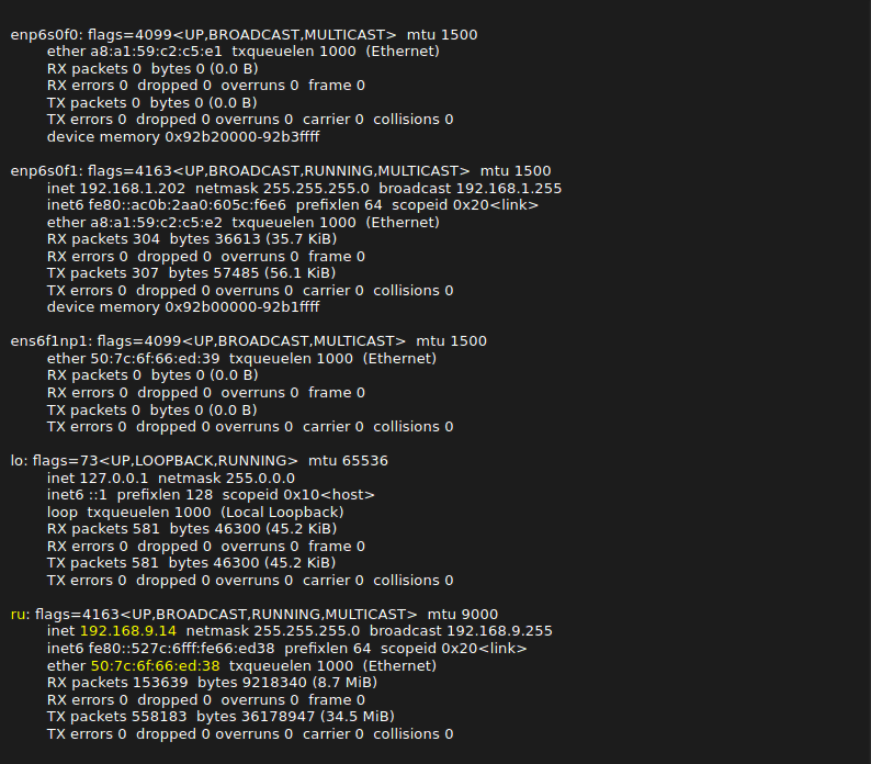
The last remaining Linux configuration is to create a VLAN. Most RUs use VLANs to differentiate C/U-Plane traffic from other traffic. My RU uses a VLAN id of 3 for C/U-Plane traffic. In order to create a VLAn with id 3, the following commands should be typed in the terminal.

Now, the output of your ifconfig command should look like as follows:
PTP Configuration
7.2 interface requires time synchronization between the DU and RU. This is done by using the Precision Time Protocol (PTP). To activate PTP in Linux, you must first install the package linuxptp by typing the following command in a terminal.
dnf install linuxptp
The linuxptp package includes ptp4l program which is is an implementation of the PTP according to IEEE standard 1588 and phc2sys program that synchronizes the system clock to a PTP hardware clock (PHC), which itself is synchronized by the ptp4l service. You can enable these 2 programs as Linux services by typing the following commands:
systemctl enable ptp4l


systemctl start ptp4l


systemctl enable phc2sys


systemctl start phc2sys
You can specify options when running these 2 programs as a service. The options are specified under /etc/sysconfig directory. The content of the pt4l option file should look like the following.
cat /etc/sysconfig/ptp4l


OPTIONS="-f /etc/ptp4l.conf"
We recommend not to put extra options for PTP in this file as sometimes they lead to PTP synchronization problems.
The content of the phc2sys option file should look like the following where -n option specifies the PTP domain name. My RU has a default PTP domain of 24. You can replace this number with your PTP domain Id.
cat  /etc/sysconfig/phc2sys


OPTIONS="-a -rr -n 24"
We highly recommend disabling NTP service to avoid conflict with PTP, by typing
systemctl disable chronyd


systemctl stop chronyd
The C1 architecture assumes that the DU is acting as the grandmaster. The following PTP configuration ptp4l.conf is compliant with the profile described in Recommendation ITU-T G.8275.1 for Telecom and has been tested with Pegatron RU.
Inside this file, you can see a section called [ru]. It refers to the interface to be used for PTP message exchanges. In my PTP config, it is set to [ru] as I have renamed the interface. If your interface name is different, remember to change this section name.
The status of the ptp4l and phc2sys services using this profile should look like the following: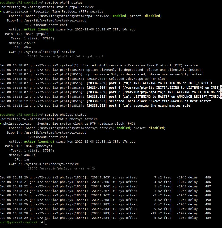
Core Network Configuration
There is no specific configuration requirement at the core network side. We have used the default mme-ims.cfg file available in each release under the /root/mme/config directoryRAN Configuration
I have used the file gnb-sa-s72.cfg for lteenb configuration. There are a couple of configuration parameters to adapt based on the RU.-
Cell configuration
The tested RU supports n79 band, so I am setting the dl_nr_arfcn and the band accordingly in my config file.
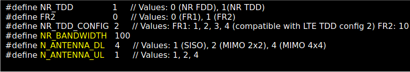
It also supports 100 MHz 4T4R. In my config file, I am configuring 4 antennas in DL and 1 in UL and a cell bandwidth of 100 MHz.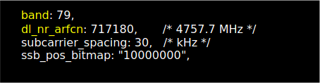
-
RF driver configuration.
The above configuration is what we have used with Pegatron PR2450. The important configuration parameters that needs to be adapted to the RU are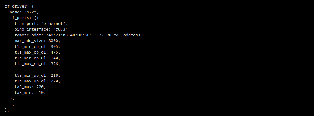
- bind_interface should be set to the interface used for C/U-Plane traffic. Previously, we created a VLAN interface called ru.3 as my RU requires a VLAN with id 3 for traffic.
- remote_addr should be set to the MAC address of the RU interface
- max_pdu_size should be set as large as possible but it also needs to be set at the RU side
- t1a_min_cp_dl, t1a_max_cp_dl, t1a_min_cp_ul, t1a_max_cp_ul, t1a_min_up_dl, t1a_max_up_dl, ta3_max timing information should be set according to the delay profile of the RU.
-
RF port configuration
The above configuration is used with my RU. The important parameters that need to be tuned per RU are listed as following: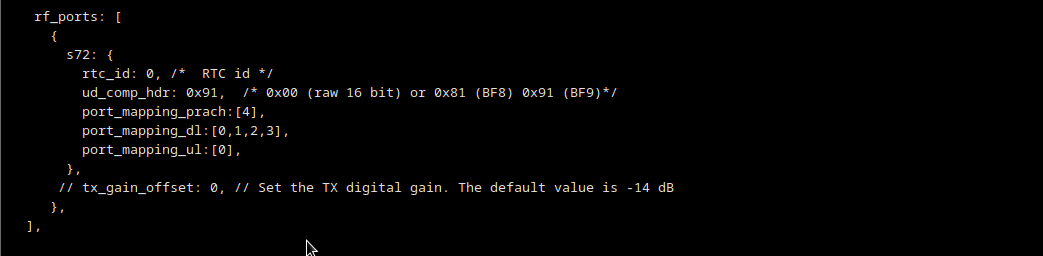
- ud_comp_hdr is set to 0x91 for BF9, as my RU supports BF9.
- port_mapping_dl, port_mapping_ul, port_mapping_prach set the port mapping for PDSCH/PDCCH, PUSCH/PUCCH and PRACH according to the the RU’s eAxC IDs for 4 antennas. As we have 4 antennas in DL, port_mapping_dl includes 4 elements referring to the RU port IDs used for the antennas in ORAN packets. In UL, however, only one RU port ID is used.
- tx_gain_offset Depending on the RU, sometimes you need to play with this parameter that sets the TX digital gain. The digital signal level should be set as high as possible without saturating the RU receiver. In my case, I have left to to its default value -14dB.
As the gNB is not aware of the RU transmission power, a manual power setting is required to improve the signal quality and the throughput.

- manual_ref_signal_power should be set to true.
- ss_pbch_block_power could be calculated at site https://5g-tools.com/5g-nr-ssb-sss-epre-power-calculator. The RU has a transmission power of 24 dBm and we are using 20 dB of attenuation at each RU antenna port.
RU Configuration
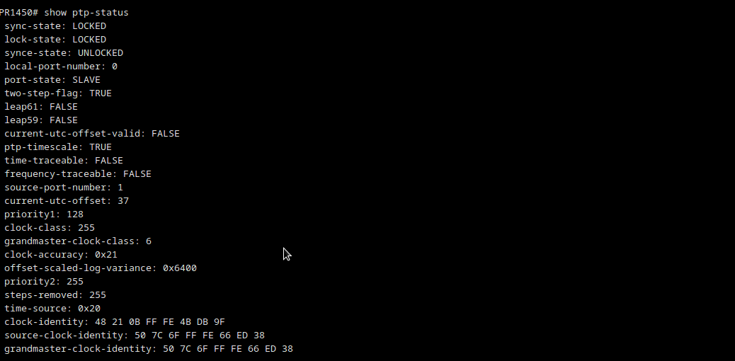
RU configuration is accessible via SSH. Previously, we set a fixed IP address to the ru interface of the Callbox to enable SSH login. Once logged into RU, the following parameters should be verified and/or set.- Check PTP domain. The domain number should be aligned with the ptp4l and phc2sys configurations and options.

- Check PTP status to make sure that it is locked. If it is not locked, check the SFP+ DAC cable as well as ptp4l and phc2sys service status at the Callbox side. Make sure that the source clock identity in the PTP status is the same as the MAC address of the Ethernet interface of the Callbox connected to the RU.
- Check the RU MTU size. It should be aligned with the gNB config parameter max_pdu_size.
You can set the MTU by typing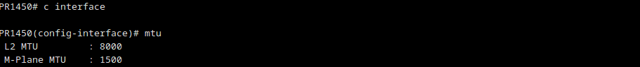
MTU 8000
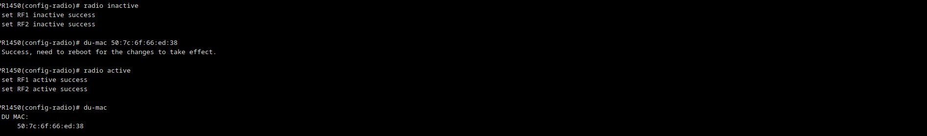
- Check the DU MAC address to be set in remote_addr

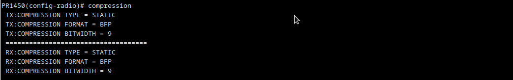
- Check the data compression configuration supported by RU. It should be aligned with ud_comp_hdr. Amarisoft only supports static compression.
- Set the DU_MAC to the MAC address of the Callbox interface connected to the RU as follows
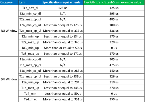
- Check the RU delay profile and set the DU timers accordingly. We have used the values in this table used by the RU vendor during IoT with other DUs.
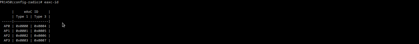
- Check the RU eAxC Ids to adapt the port_mapping_dl, port_mapping_ul, port_mapping_prach according to RU antenna ports mappings. Type 1 refers to PUSCH/PDSCH/PUCCH/PDCCH while type 3 is for PRACH.
- Set the FS offset. For frequency domain IQ data, 0 dBFS shall be the maximum power level which can be carried by one subcarrier. The smallest non-zero IQ power level is defined by the interface resolution.
It can be expected that an O-RU will normalize any received DL value to its internal representation of full scale so that a 0 dBFS can be properly handled. This is handled by the FS offset parameter of the RU.
Amarisoft IQ data are coded with 15 bits float type varying between -32768 and 32767. PR1450 supports default O-RAN WG4 CUS specification of full scale being 2^23. So the fs_offset of the RU should be set to 23-15=8. Fs_offset is mostly useful for UL as the DU’s IQ range is lower than 23 bits, hence the RU needs to adjust the IQ value to avoid overflow in DU side.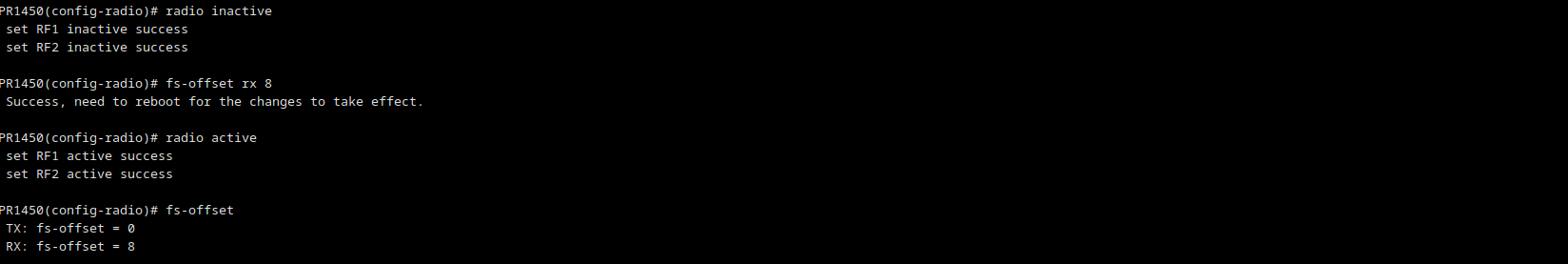
-
Set the TX gain correction. PR1450 Indoor RU follows O-RAN.WG4.CUS.0-R003-v12.01 specification for digital power scaling in chapter 8.1.3 .
The internal gain in Tx path will expect I/Q power level in full scale of 0 dBFS ⇔ average(I^2+Q^2) = 2^46 assuming BF9 compression is used with 9-bit mantissa 2's complement + 4-bit exponent compression. As Amarisoft I/Q power level is lower than this full scale, then the TX gain should be changed via the gain-correction configuration in the RU. The gain-correction can be calculated as below:
tx_gain_correction (dB) = 20*log10(2^23 / sqrt(mean(I^2 + Q^2)))
For Amarisoft with average(I^2+Q^2)=2^30, the tx_gain_correction should be set to 20*log(2^8)=48.16 dB.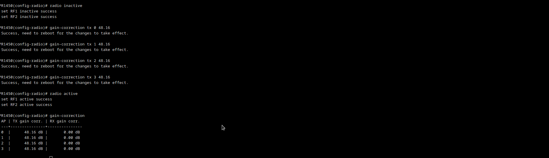
-
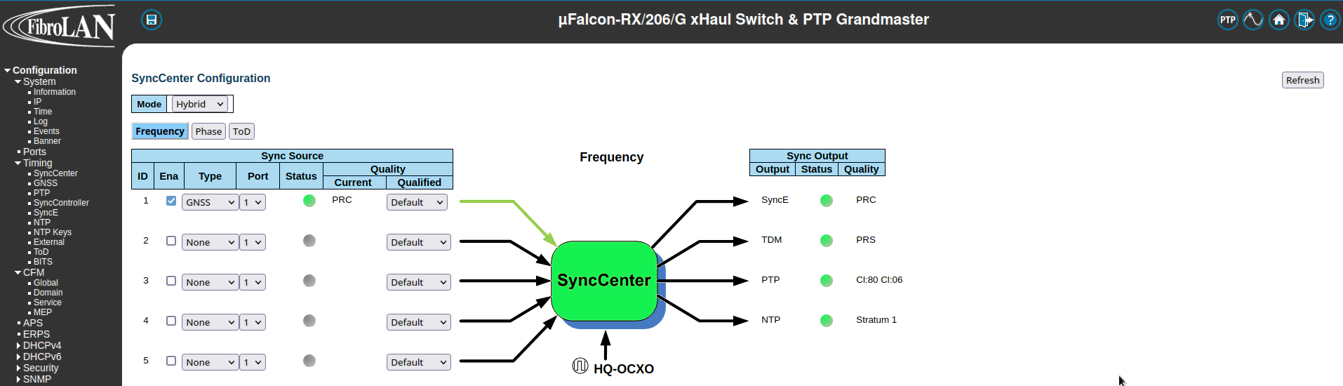
GPS Sync: The Fibrolan switch should be connected to an external GPS to ensure that the PTP grandmaster is correctly synchronized by a reference clock. In order to enable GPS, you should go to Configuration > Timing > SyncCenter and select GNSS as Sync Source Type. Wait for the status color to be green which means that GPS is correctly locked as shown below.
-
PTP Clock Configuration. In order to create a PTP clock as grandmaster, go to Configuration > Timing > PTP and add a new PTP Clock. Select Device Type: Master Only and Profile: G8275.1 as shown below.
Next, click on the Clock Instance to edit. You should see a screen as shown below: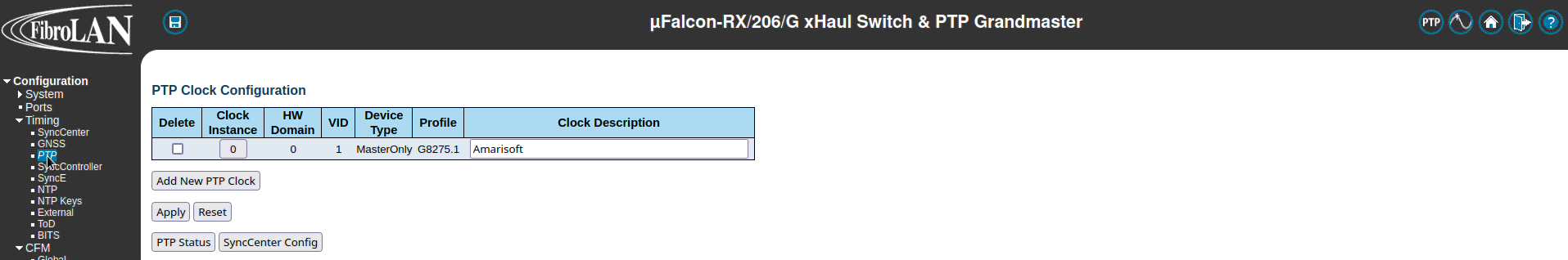
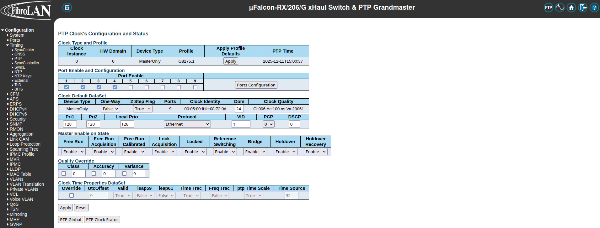 Enable the ports that should have PTP. In our case, it is ports 1 and 2 as the Callbox is connected to port 1 and RU to port 2. Make sure that the priority fields Pri1 and Pri2 are set to 128 and the PTP domain is 24. By default the VLAN ID of the PTP clock is set to 1 but you can change it by editing the VID field in Clock Default Dataset . Click on Apply button to save the configuration.
-
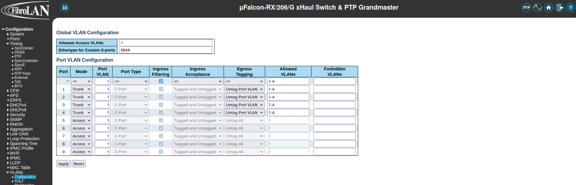
VLAN Configuration. VLANs must be configured correctly to allow the DU and RU to receive the PTP sync from the grandmaster and to communicate. To configure VLANs per port, go to Configuration > VLANs > Configuration . Configure the ports you want to use as Trunk ports. Trunk ports enable switch access ports to handle more than one VLAN and separate traffic accordingly. Set the Port VLAN to 1 which is the default VLAN ID of the PTP clock. In the Allowed VLANs field you can set
a range or specify specific VLANs. For example, here we are specifying 1-4 meaing that all traffic with VLAN IDs from 1 to 4 will be routed. For this test, we could have set the allowed VLANs to 1, 3, where 1 is for PTP and 3 refers to the VLAN ID used by DU/RU for the C/U-plane traffic. Set Egress Tagging as Untag Port VLAN meaning frames classified to the Port VLAN are transmitted untagged. Other frames are transmitted with the relevant VLAN tag.
UE Simulator Configuration
The UE configuration file ue-sa-pegatron.cfg has been used during the test. This is basically the same as the one delivered in each release for NR SA. It has only been adapted to the n79 band with the same nr_arfcn and ssb_arfcn as the ones used by DU+RU.LLS-C3 Test Setup
n this architecture, the RU and the Callbox are connected to the switch. The switch plays the role of the PTP Grand master, providing the clock and synchronization information to the Callbox and the RU. This is depicted in the following diagram.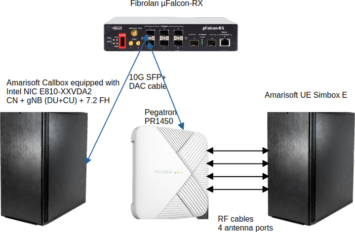
Configuration
This section provides the configuration parameters for PTP and the switch. All other configuration steps are the same as for C1 architeture.PTP Configuration
In this architecture, the Callbox acts as a slave taking the clock from the PTP switch. The following PTP configuration ptp4l.conf can be used when the PTP grandmaster clock is provided by an external switch. The status of the ptp4l and phc2sys services using an external PTP grandmaster should look like the following: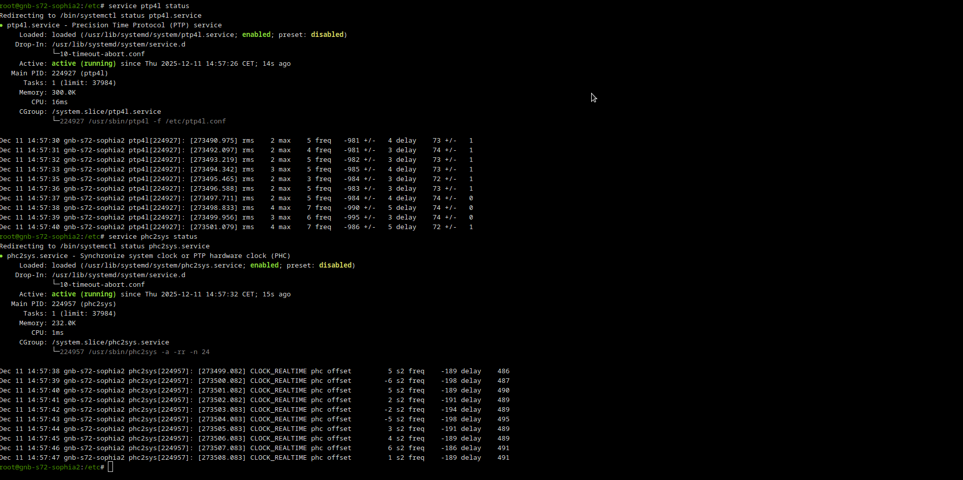
Fibrolan Falcon Switch Configuration
Falcon-RX is a 5G xHaul Timing Aware O-RAN Switch & PTP Grandmaster. In our setup, this switch is used to provide the clock and the timing synchronization to the Callbox and the RU. The following steps are required to correctly configure the switch:Test Execution : Callbox + RU + UE Simbox
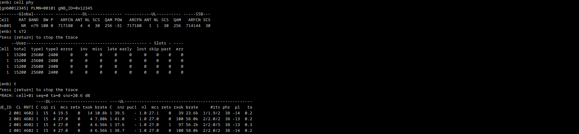
First thing is to check the data communication between DU and RU by typing t s72 in enb console. You should see type 1 and type3 data going through the interface as can be shown in the following screenshot. Making a power_on at the UE console, you should be able to see a PRACH message being received by the gNB and the whole RRC connection and attach procedure in the logs.